Week 10 - battery cooling methods
Problem Statement:
Perform the heat transfer analysis using ANSYS-Fluent software for the cylindrical Lithium ion Battery with heat generation boundary condition. Create an enclosure and use air as the working fluid for cooling the battery back system (4 x 2). Take air inlet temperature as 26°C and space between the batteries as 2 mm.
Property of the Lithium-ion Battery
Nominal Voltage = 3.6 V
Nominal capacity = 2.2 A
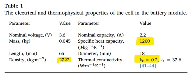
Density = 2722 kg/m3
Specific heat = 1200 J/kg.K
Thermal Conductivity = 37.6 W/m.K
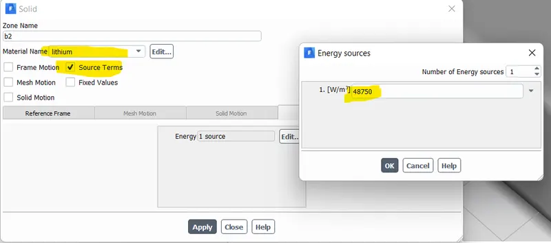
Heat Source = 48750 W/m3 (1.5 C discharge rate)
Size of the Battery = 18 mm diameter and 65 mm height.
Expected results:
• Explain why battery cooling is needed. And give a brief description about various techniques for battery cooling.
• Perform Mesh independent study for any one case and based on your judgment use the more suitable model for further cases.
• Run the simulation by varying the velocity of air as 3, 5 and 10m/sec and discuss the results.
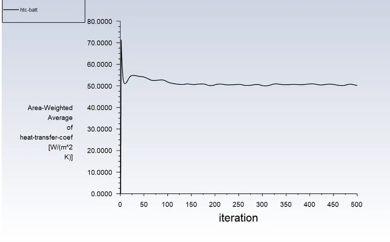
• Find out the maximum temperature and heat transfer coefficient obtained by the battery.
• Based on the results and on your judgment, select one case (3, 5 or 10 m/s) and vary the space between the batteries as 2, 4 and 6 mm, then discuss the results.
• Prove that the simulation has achieved convergence with appropriate images and plots (Velocity and temperature contour plots on the cut planes).
• Create the animation to observe the temperature distribution and velocity vector.
• Summarize the results in tabulation/ graphical form.
• State the inferences based on the results.
Case set up
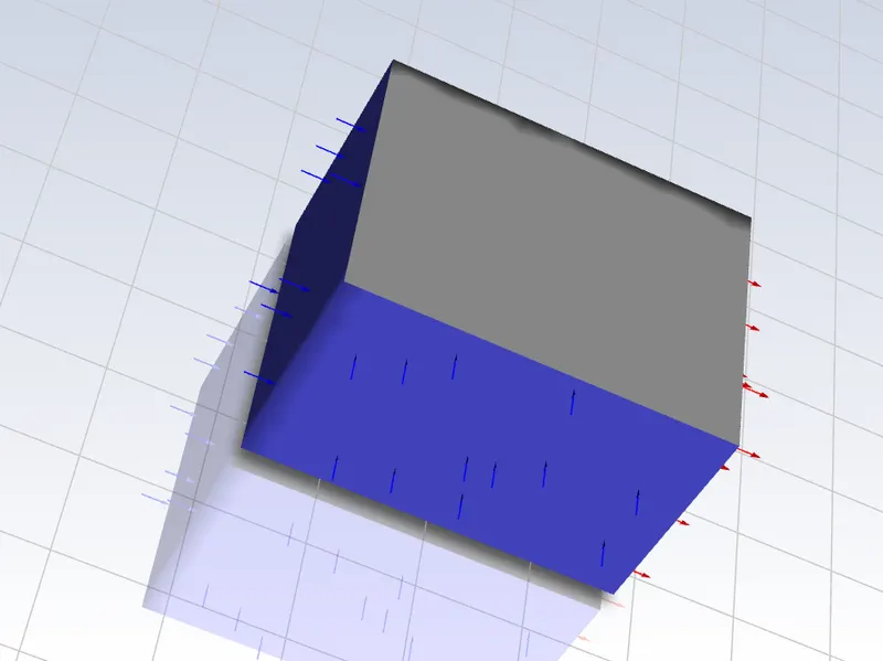
Set up a model as shown below
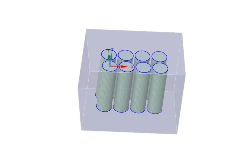
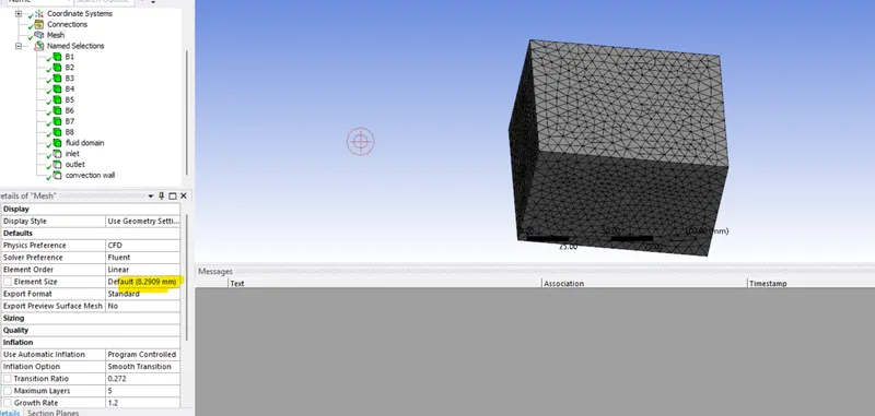
Check the optimum mesh
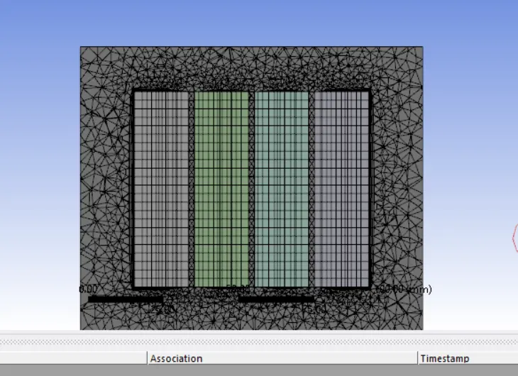
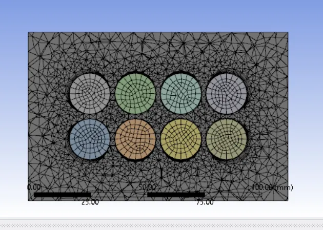
Meshing done with a baseline mesh of 8.29 mm
Open Fluent
Turbulence model:k-omega SST
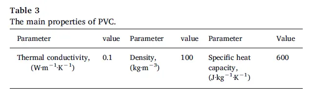
Create material Lithium and PVC with following specification
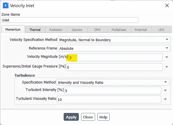
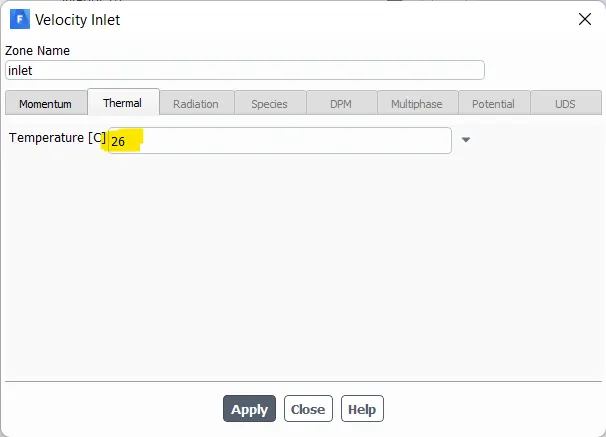
Inlet velocity = 3 m/s, Inlet temperature = 26 *C
Set battery to lithium and set the energy source value
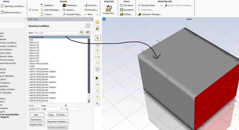
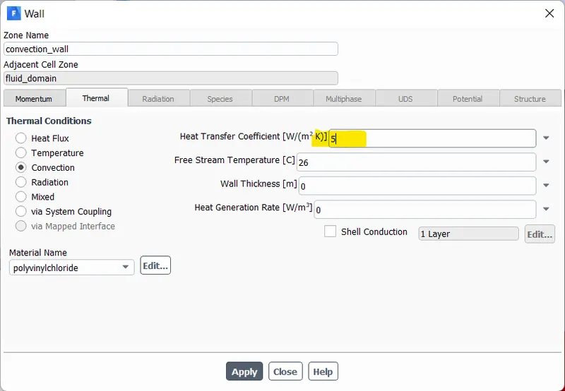
Convective htc=5 W/m2K for the outer wall enclosure, material = pvc
 v
v
Set battery wall to lithium
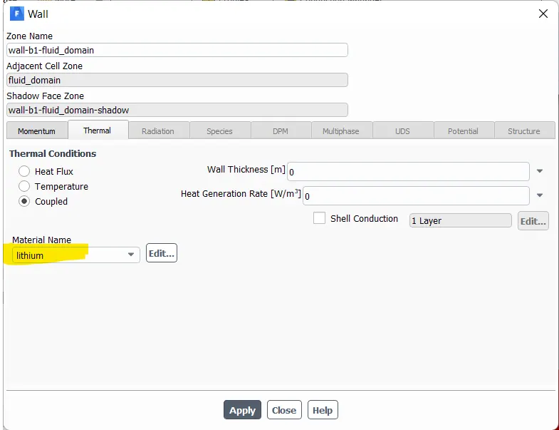
Run Simulation
Result
a) Mesh = 8 mm
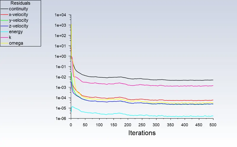
Scaled Residual
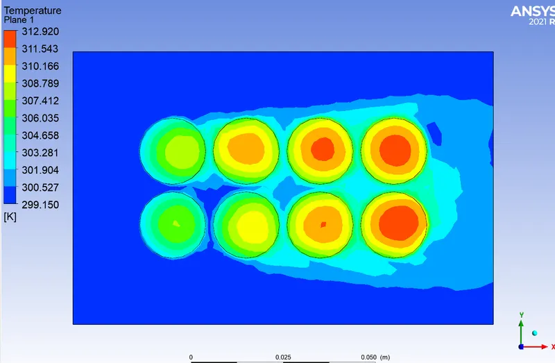
Temperature plot
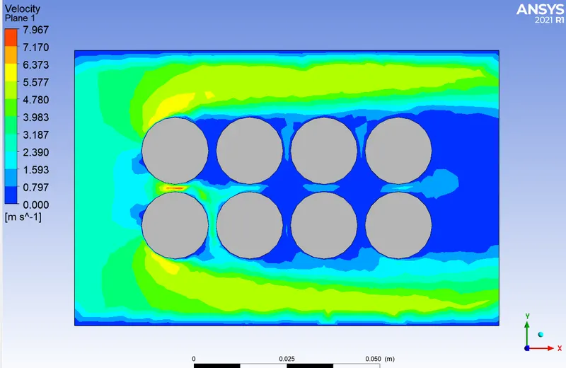
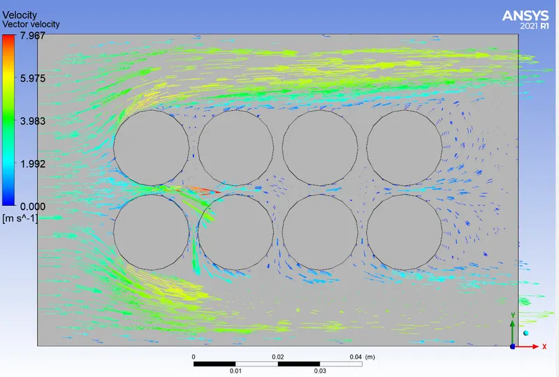
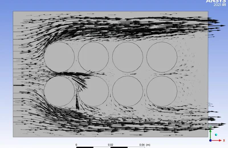
Velocity plot
Temperature chart through cut line
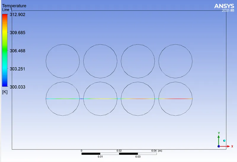
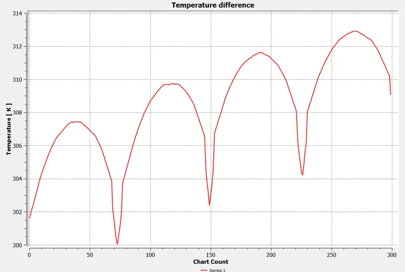
Here, Delta T = 312.902- 300.033 = 12.869.
This is the temperature difference obtained
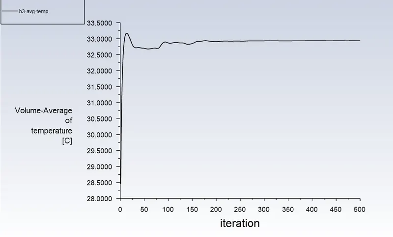
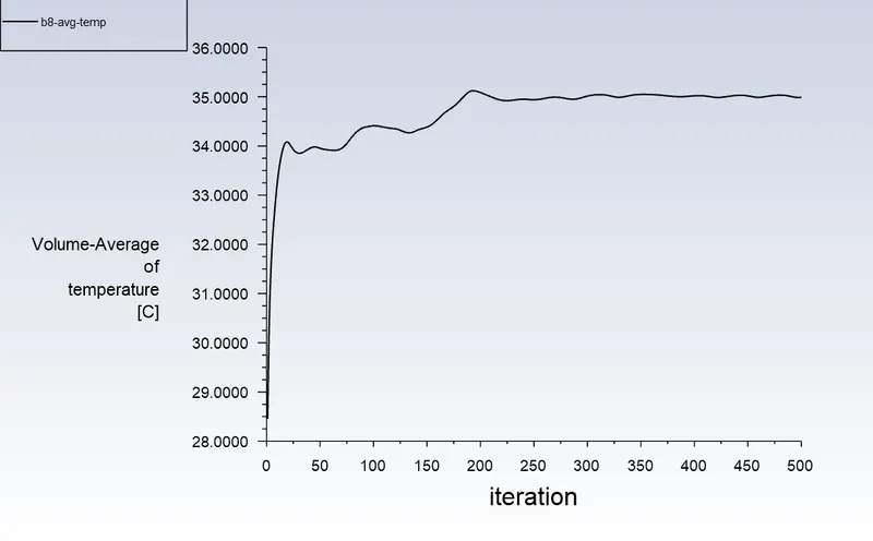
b) Mesh = 8 mm, body sizing(battery) = 2 mm
Scaled Residual
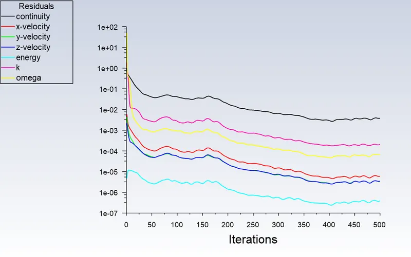
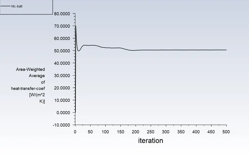
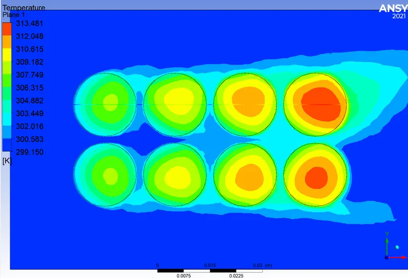
Temperature plot
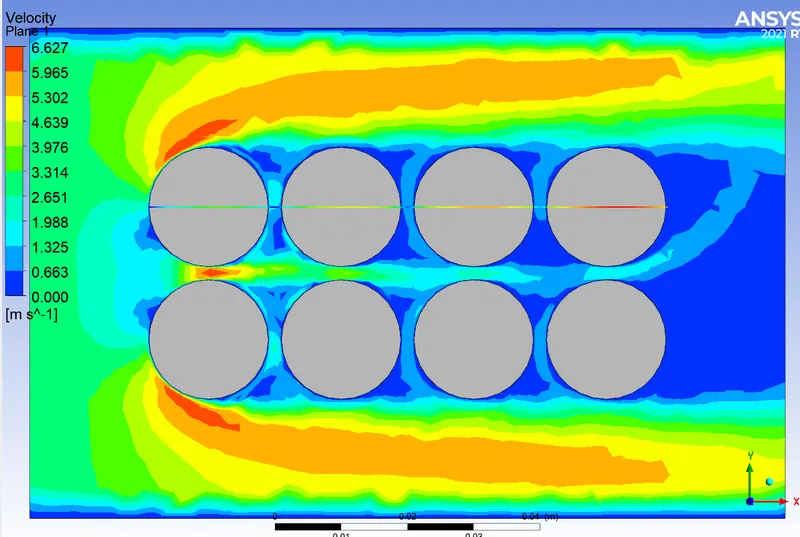
Velocity plot
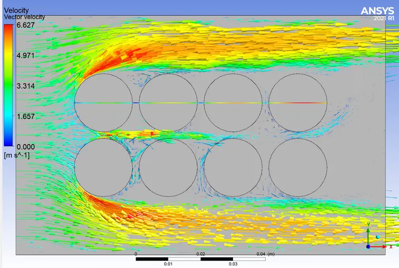
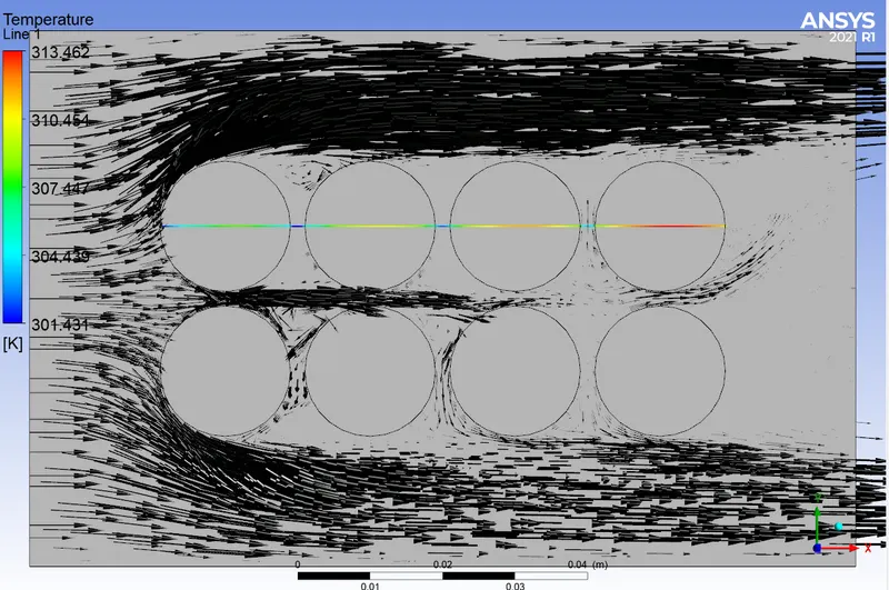
Temperature chart through cut line
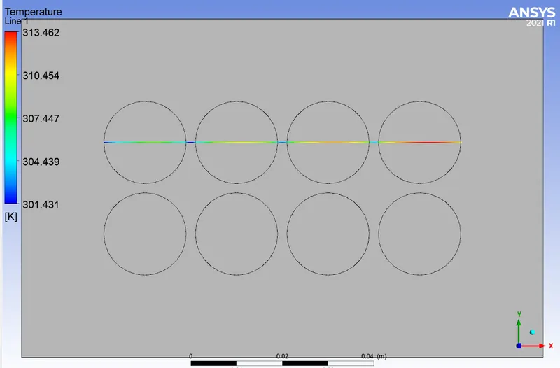
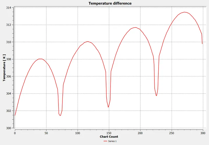
Here, Delta T = 313.462- 301.431 = 12.031.
This is the temperature difference obtained
Maximum temp obtained at mid plane = 313.481 K
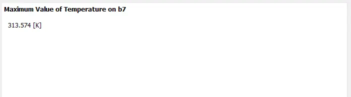
Maximum temp obtained if we consider full battery volume = 313.574 K
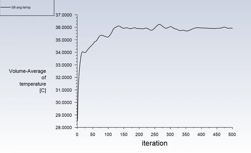
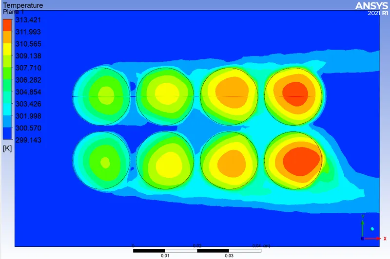
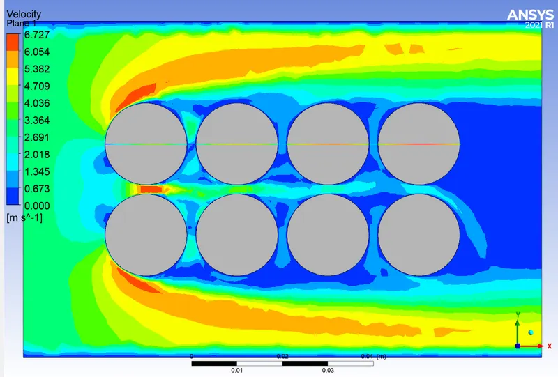
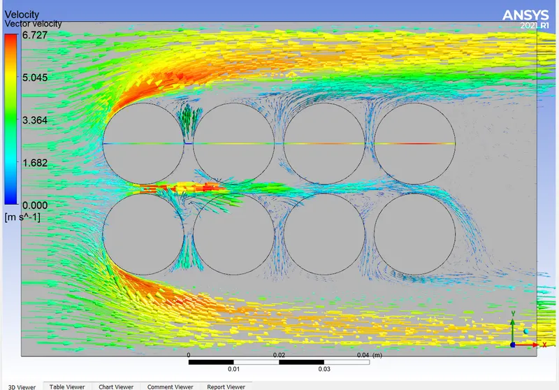
c) Mesh = 4 mm, body sizing(battery) = 1.5 mm
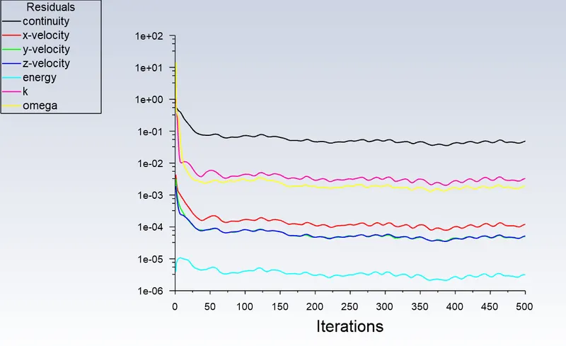
Scaled Residual
Temperature plot
Velocity plot
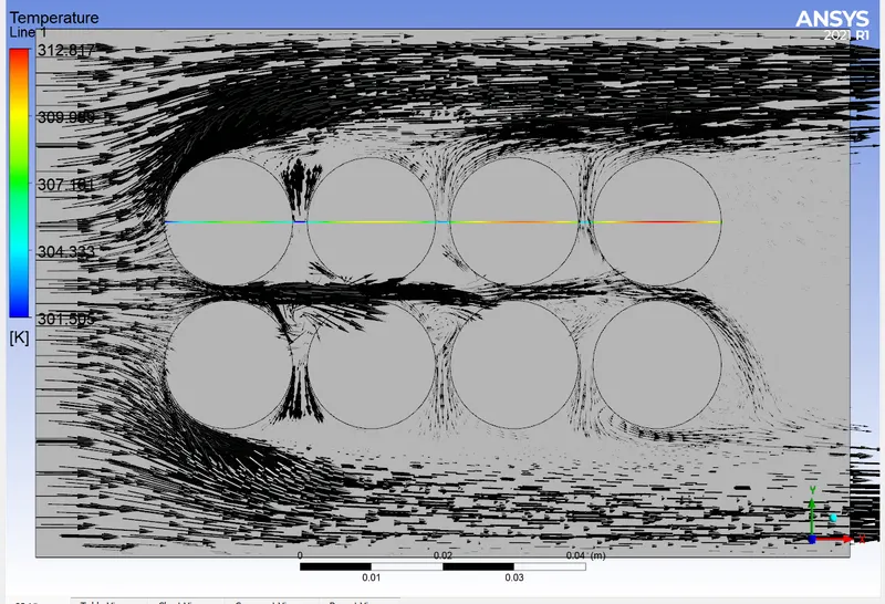
Temperature chart through cut line
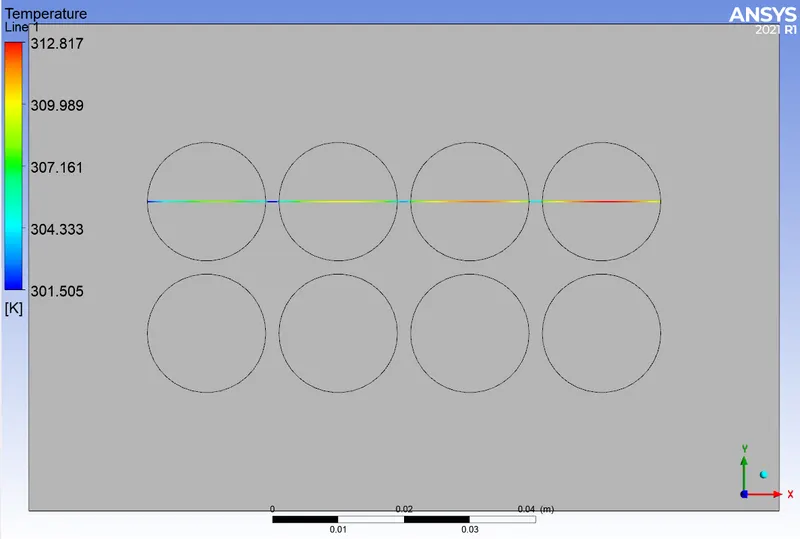
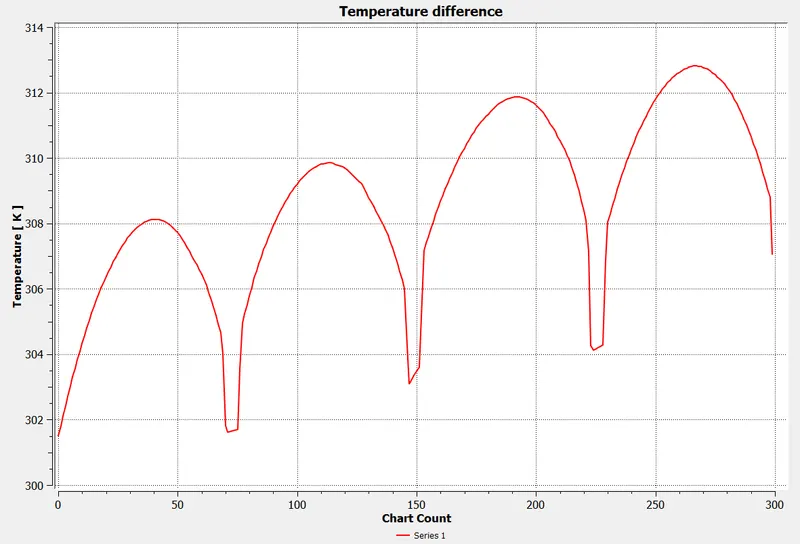
Here, Delta T = 312.817- 301.505 = 11.312.
This is the temperature difference obtained
INFERENCE ON MESH INDEPENDENT STUDY
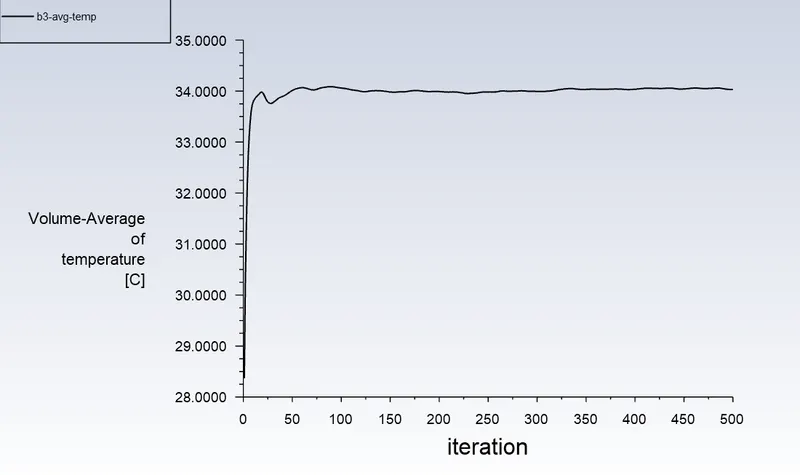
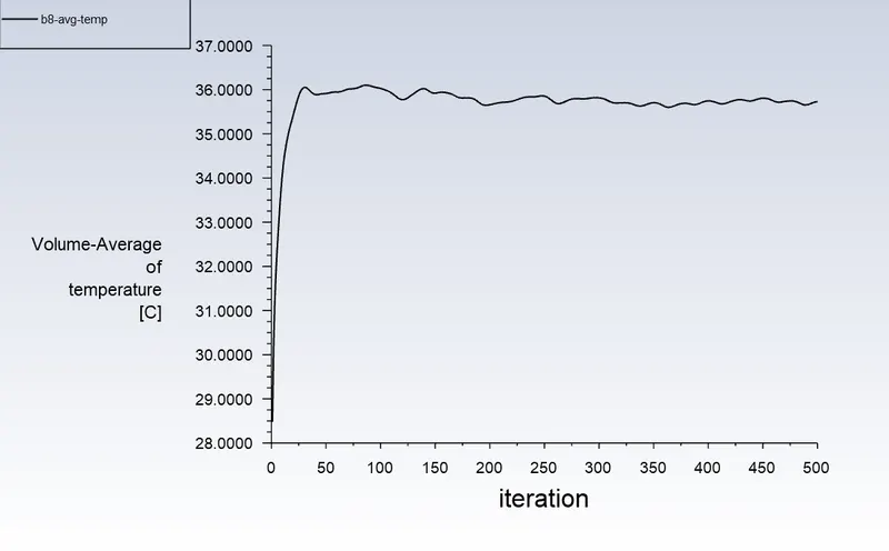
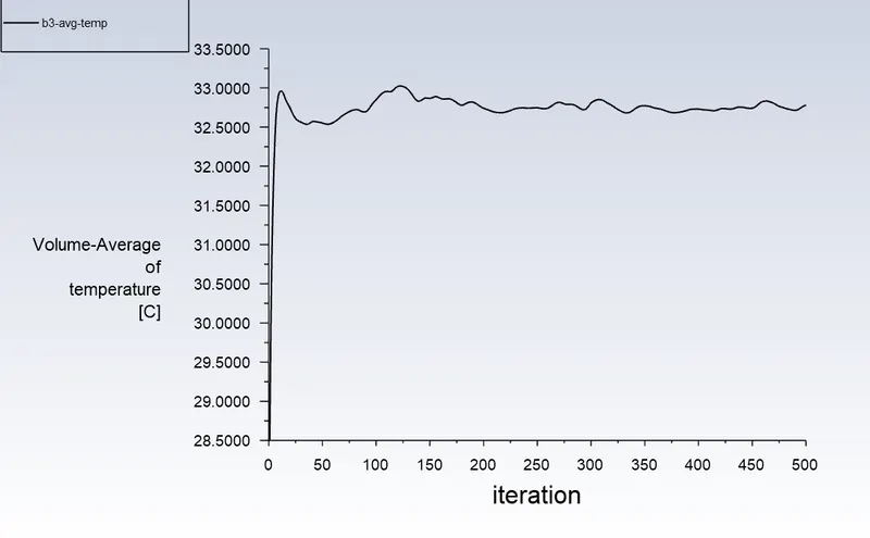
The Volume average of battery 3(b3) is taken for mesh independent study. There is not much difference in temperature between case b and case c. As the cell count is less in case b, case b is choosed for further simulation.
Case b: Mesh=8 mm, Body sizing(battery)=2 mm
Space changing study
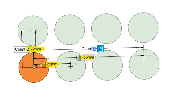
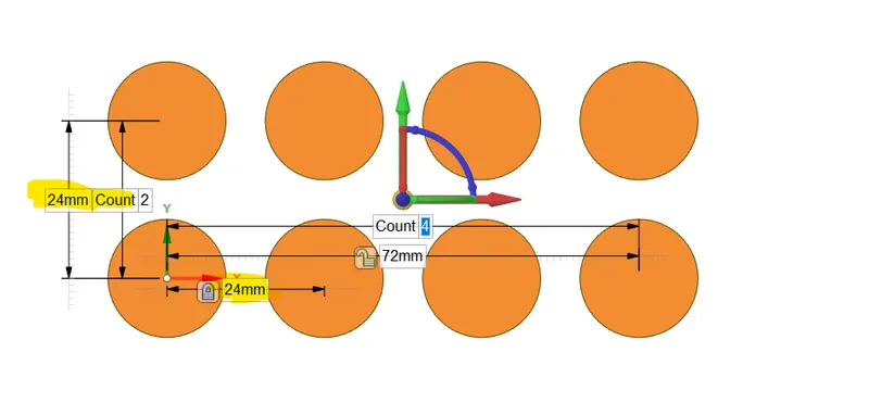
a) Minimum distance between battery = 4 mm, pitch = 22 mm
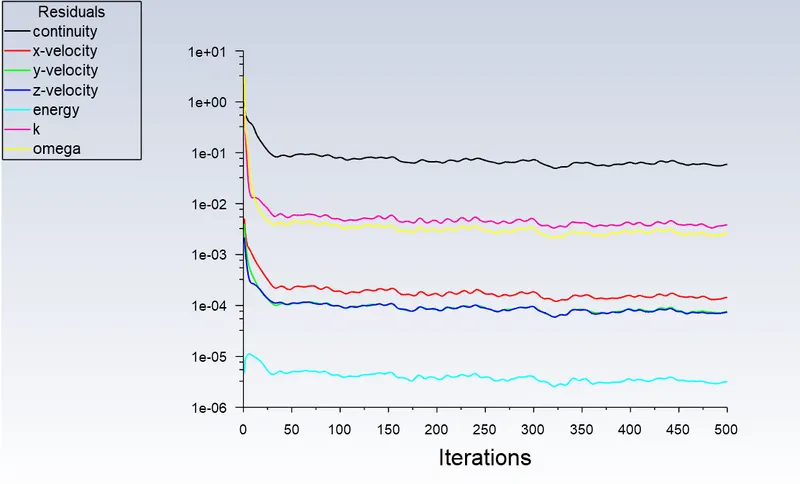
Scaled Residual
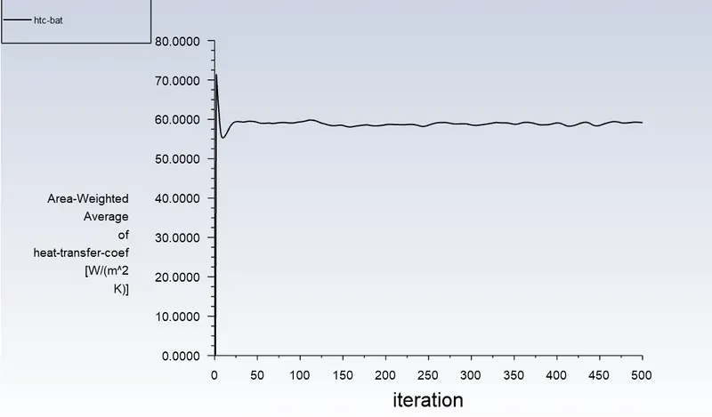
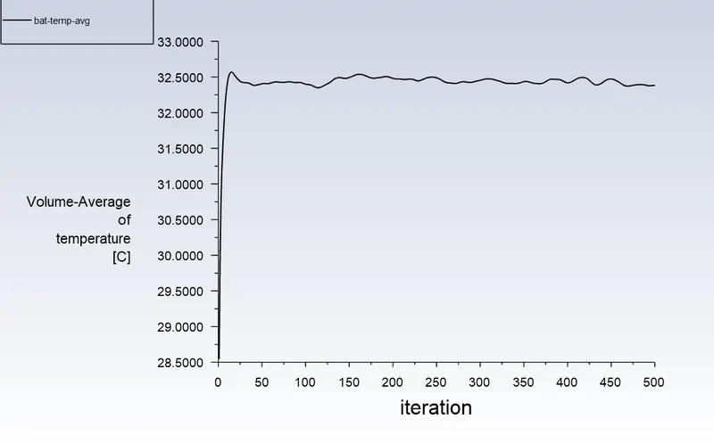
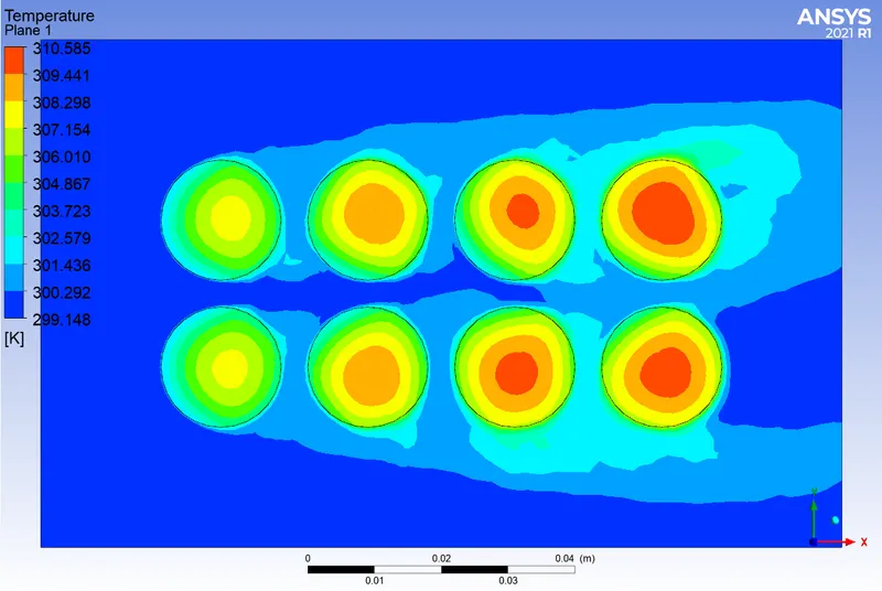
Temperature plot
Velocity plot
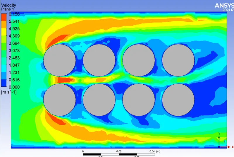
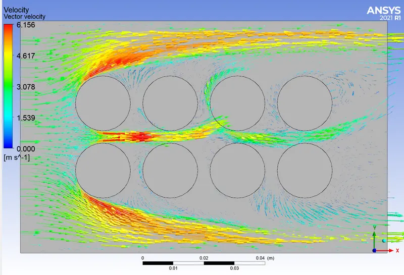
Temperature chart through cut line
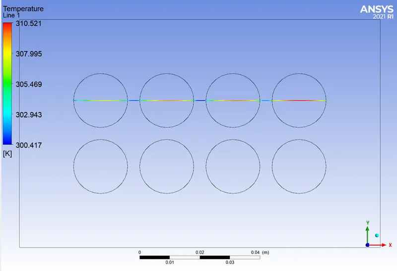
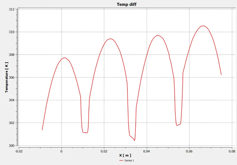
Here, Delta T = 310.521- 300.417 = 10.104.
This is the temperature difference obtained
Maximum temp obtained at mid plane = 310.585 K
Maximum temp obtained if we consider full battery volume = 310.656 K
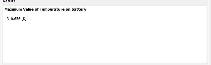
Maximum temperature difference at mid-plane between 2 mm and 4 mm spacing = 313.48 - 310.52=2.96. (around 3)
Maximum temperature difference on entire volume between 2 mm and 4 mm spacing = 313.57 - 310.65=2.92 (around 3).
b) Minimum distance between battery = 6 mm, pitch = 24 mm
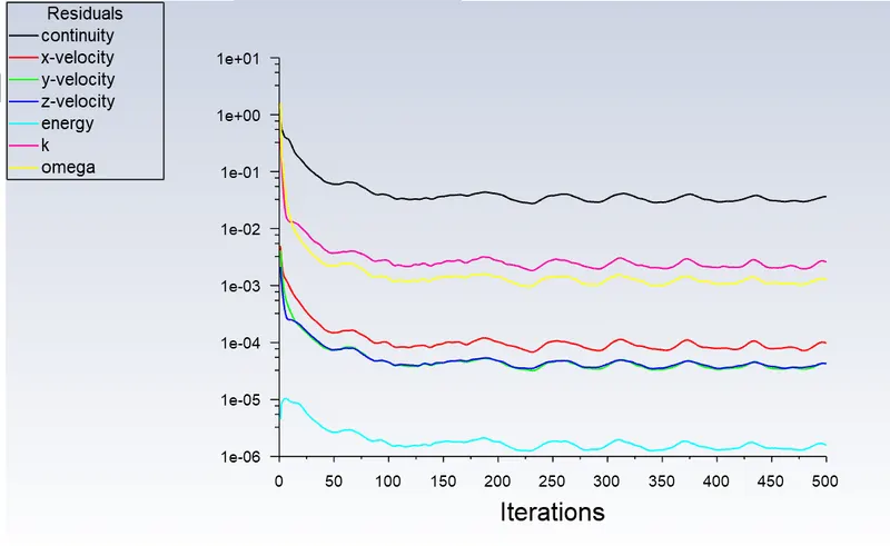
Scaled Residual
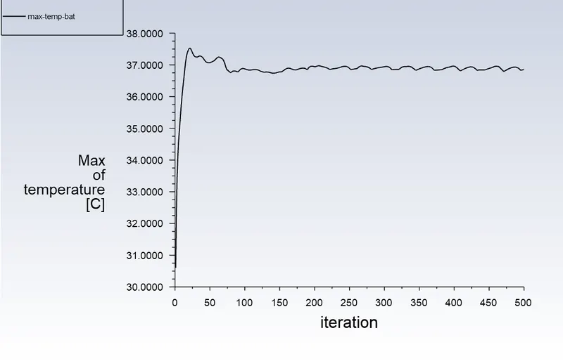
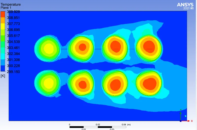
Temperature plot
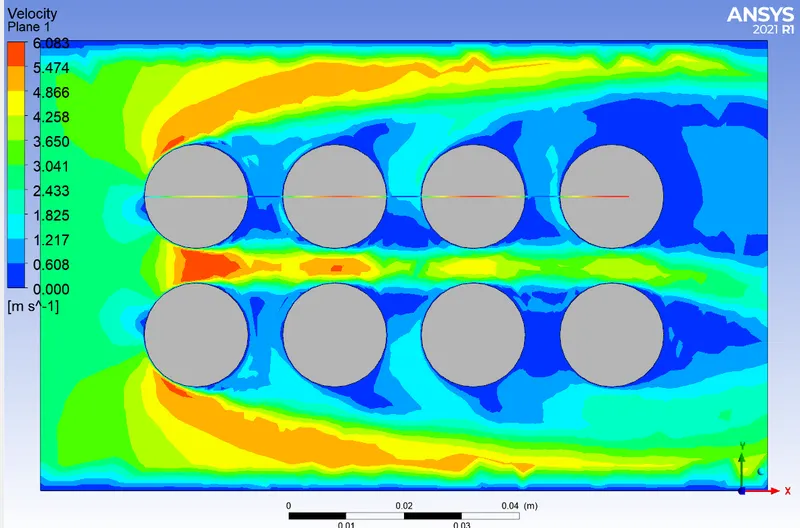
Velocity plot
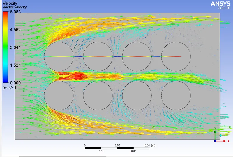
Temperature chart through cut line
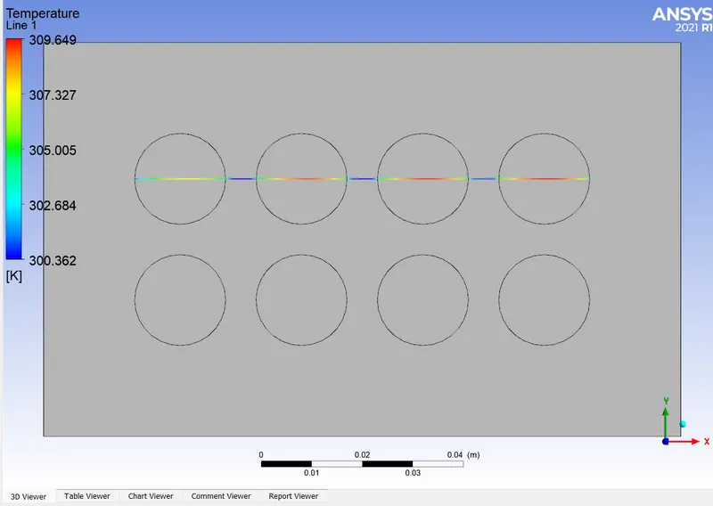
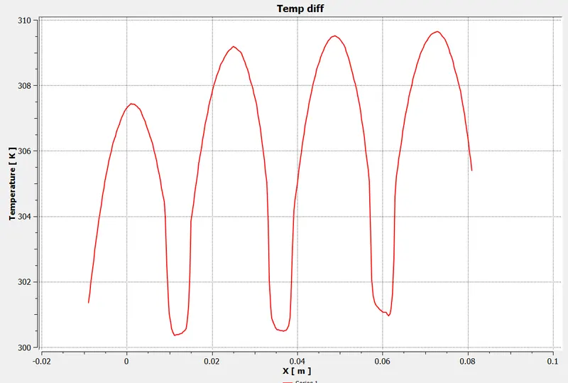
Here, Delta T = 309.649- 300.362 = 9.287.
This is the temperature difference obtained
Maximum temp obtained at mid plane = 309.929 K
Maximum temp obtained if we consider full battery volume = 309.997 K
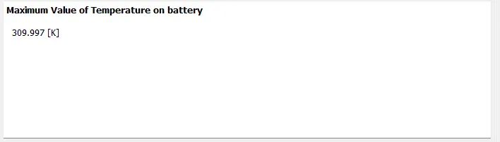
Maximum temperature difference at mid-plane between 4 mm and 6 mm spacing = 310.52-309.93=0.59. (around 0.6)
Maximum temperature difference on entire volume between 2 mm and 4 mm spacing = 310.65-309.997=0.653 (around 0.6).
INFERENCE ON SPACE CHANGE STUDY
a) When the space between cells are 2 mm, the maximum temperature = 313.57 K.
b) When the space between cells are 4 mm, the maximum temperature = 310.65 K.
c) When the space between cells are 6 mm, the maximum temperature = 309.997 K.
By changing the space between cells to 4 mm, the maximum temperature get reduced by 3 K/C, with some small increase in volume of enclosure. But when the space between cells changed to 6 mm, there is no significant change in temperature, temperature is decreased to around 0.6 K/C.
So, the 4 mm spacing between cells is choosed for further study.
Changing inlet velocity
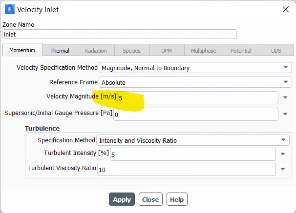
b) v= 5 m/s
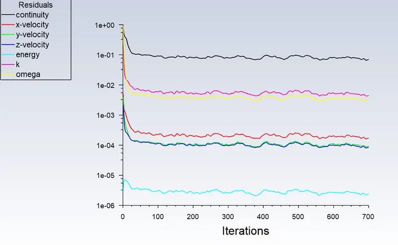
Scaled Residual
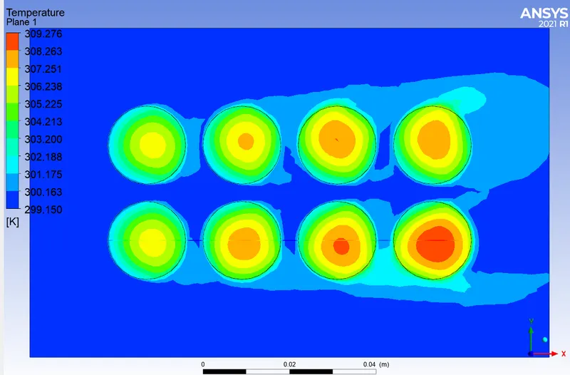
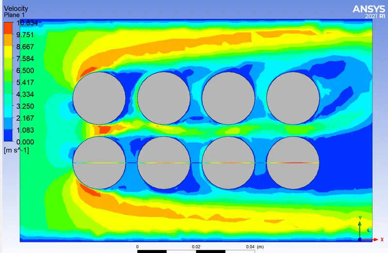
Temperature plot
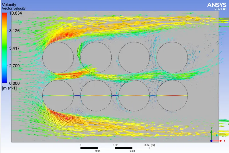
Velocity plot
Temperature chart through cut line
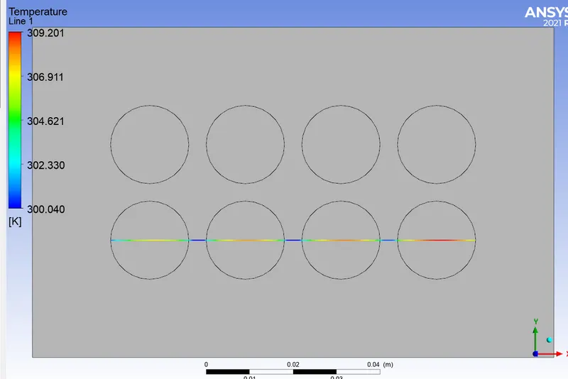
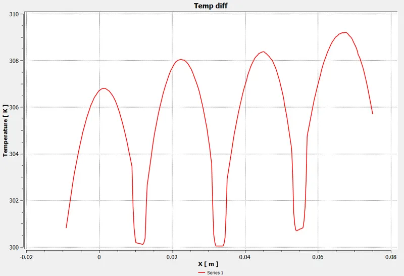
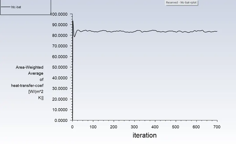
Here, Delta T = 309.201- 300.040 = 9.161.
This is the temperature difference obtained
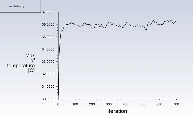
Maximum temp obtained at mid plane = 309.276 K
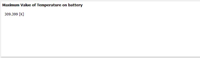
Maximum temp obtained if we consider full battery volume = 309.399 K
--------------------------------------------------------------------------------------------------------------------------------------------------------------------------------------
Changing inlet velocity
c) v= 10 m/s
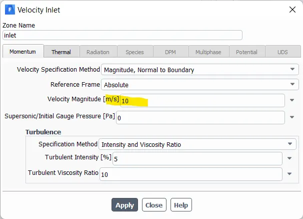
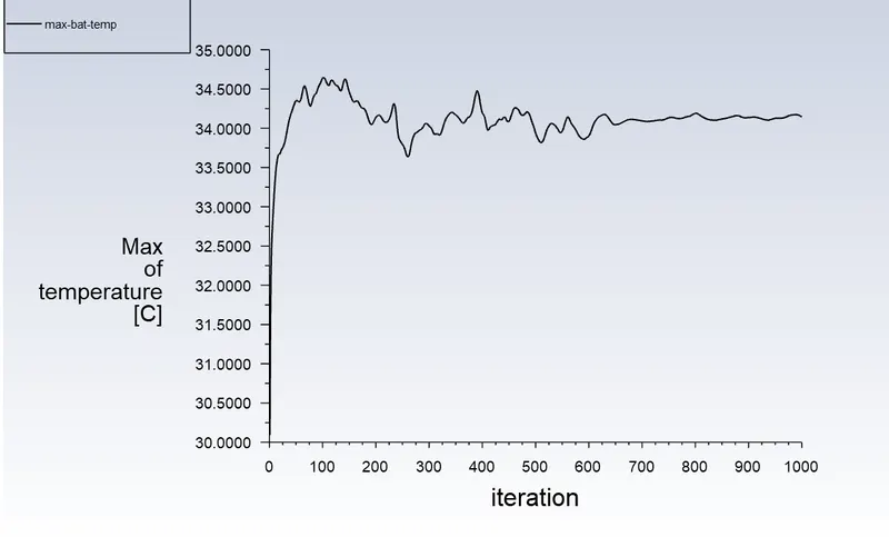
Scaled Residual
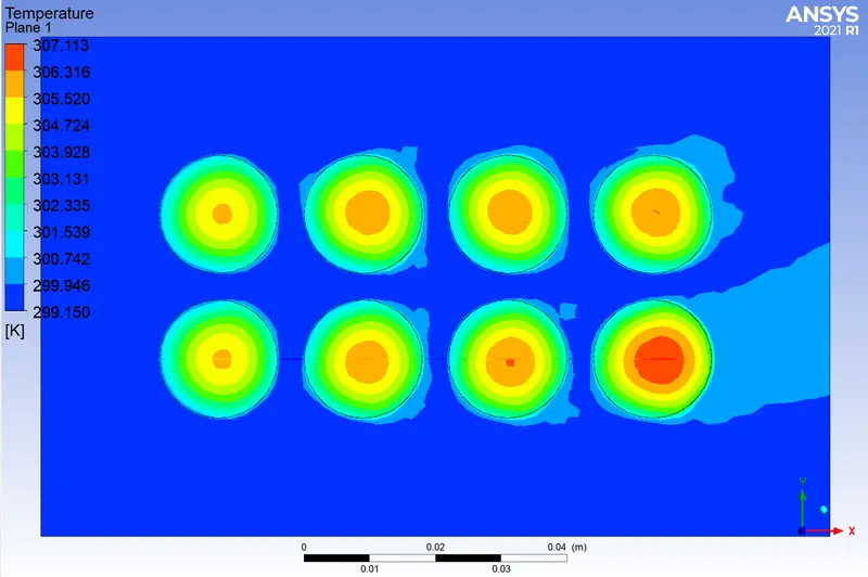
Temperature plot
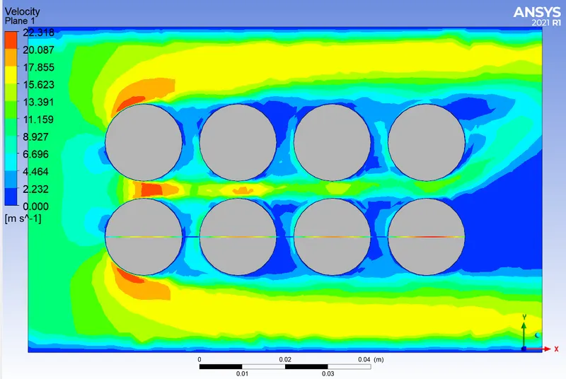
Velocity plot

Temperature chart through cut line
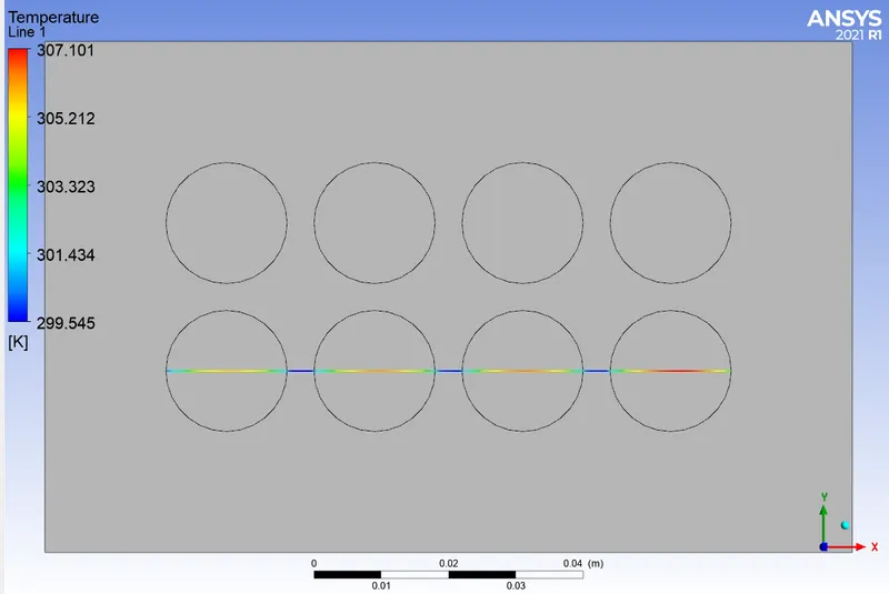
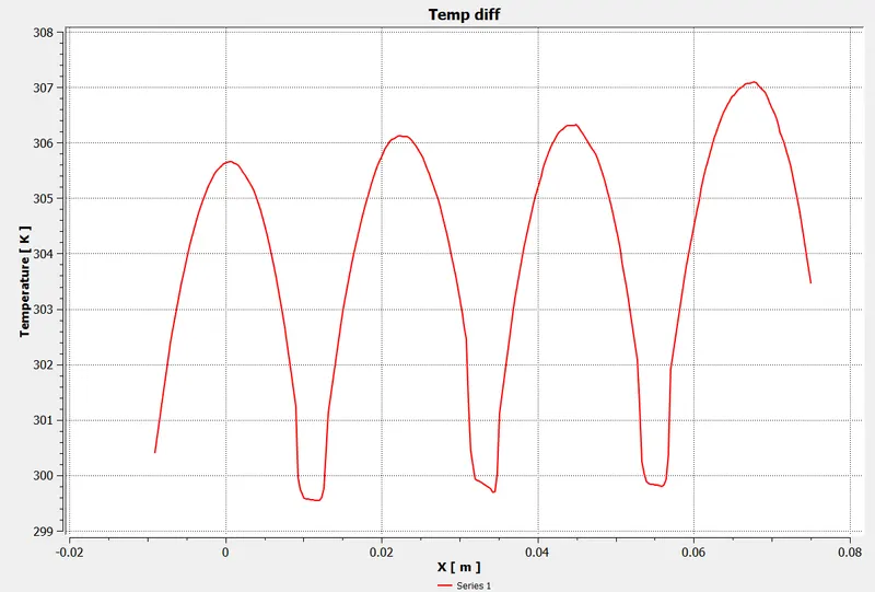
Here, Delta T = 307.101- 299.545 = 7.556.
This is the temperature difference obtained
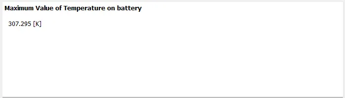
Maximum temp obtained at mid plane = 307.113 K
Maximum temp obtained if we consider full battery volume = 307.295 K
CONCLUSION for 2 X 4 cell battery pack
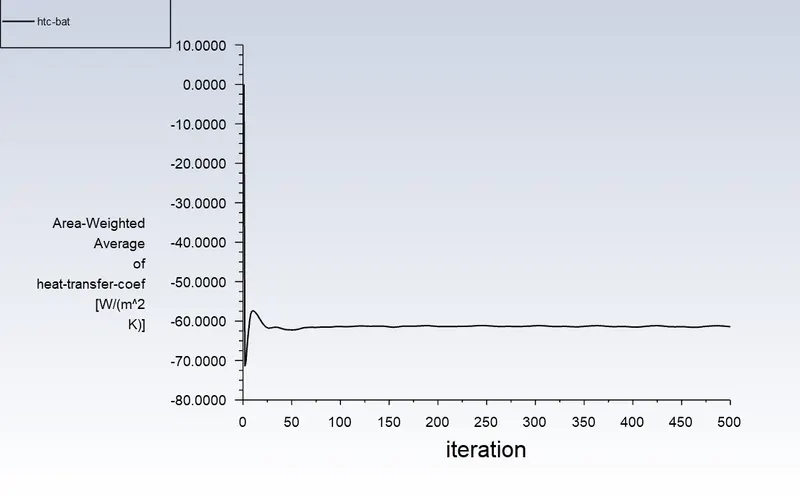
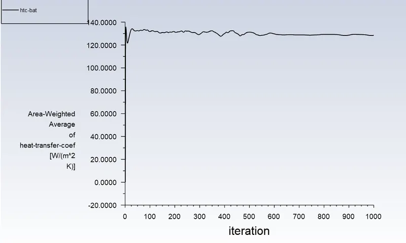
As the inlet velocity increases from 3 m/s to 5 m/s, there is no significant change Delta T. But when the inlet velocity increased to 10 m/s, there is nearly 1.7 K decrease in Delta T. The surface heat transfer coefficient is around 130 W/m2K when the inlet velocity is 10 m/s. The surface htc was around 60 W/m2K when the inlet velocity is 3 m/s. The reduction in delta T is due to increase in surface htc when changing the velocity from 3 m/s to 10 m/s.
In 2 X 4 battery pack, the spacing between cells of 4 mm is chosen as optimum model, because of reduction of maximum temperature of around 3 K,when compared to spacing of 2 mm.
Calculation using 2 inlet
a) Top Inlet,v=10 m/s.
Mesh: case b : Mesh size = 8 mm, body sizing=2 mm
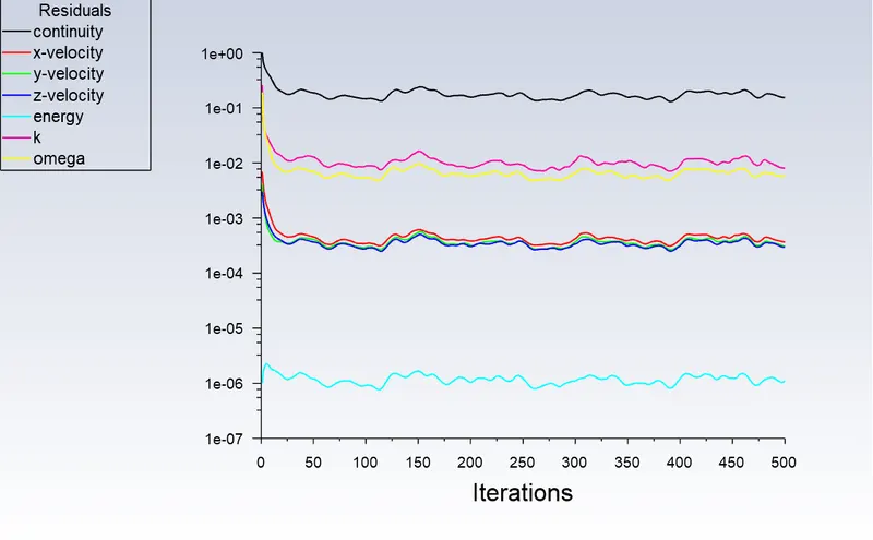
Scaled Residual
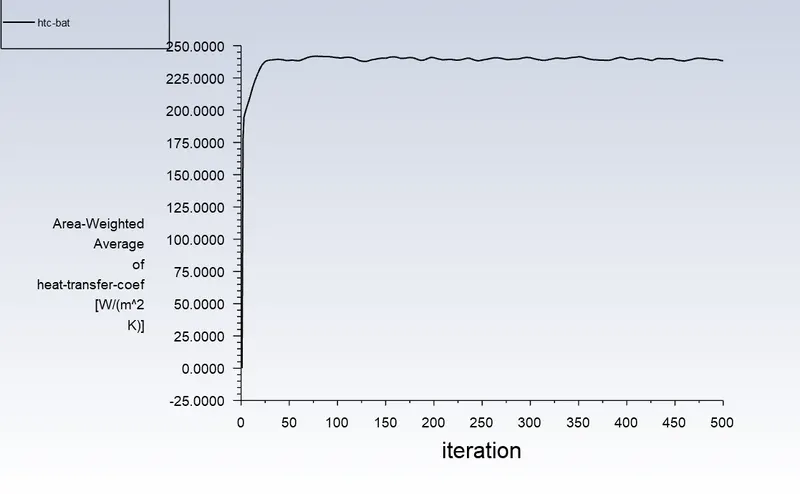
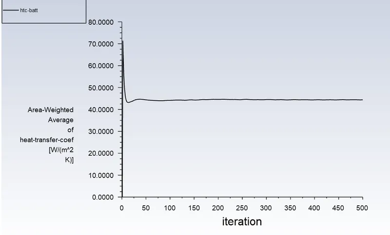
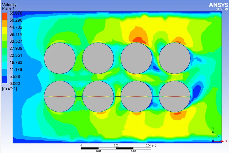
Value = 238.32 W/m2K
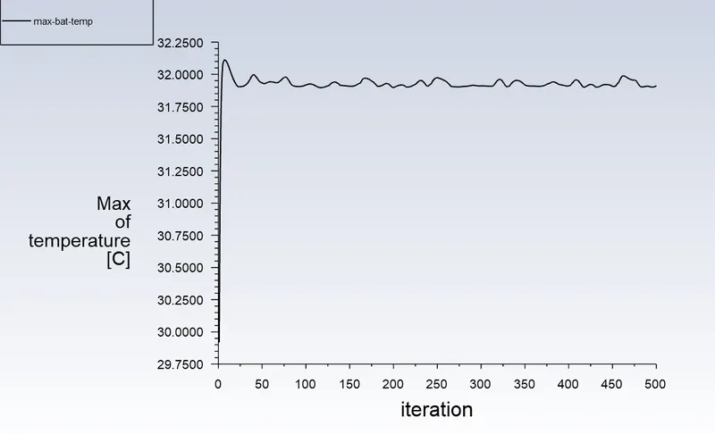
Value = 31.91 *C
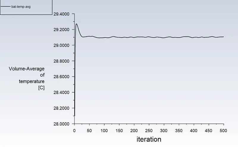
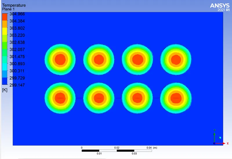
Temperature plot
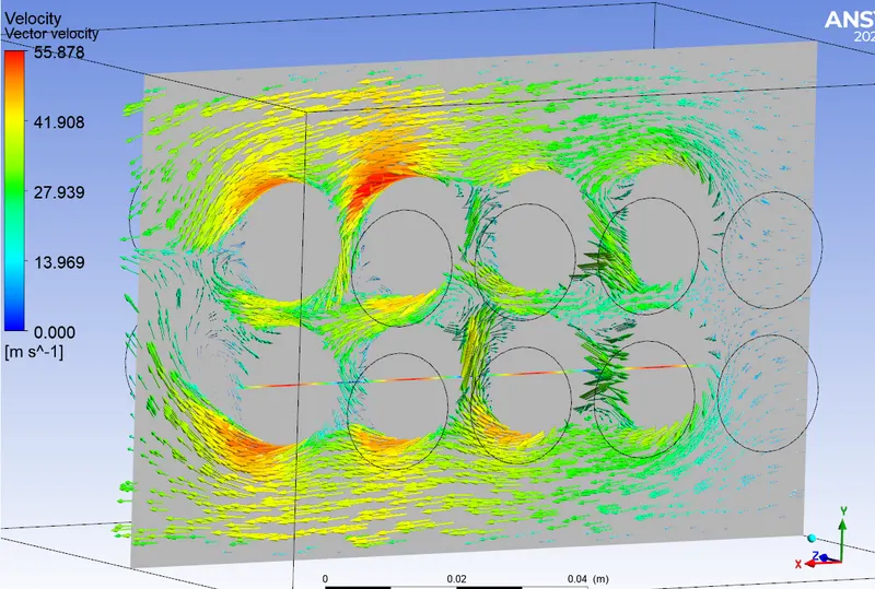
Velocity plot
Temperature chart through cut line
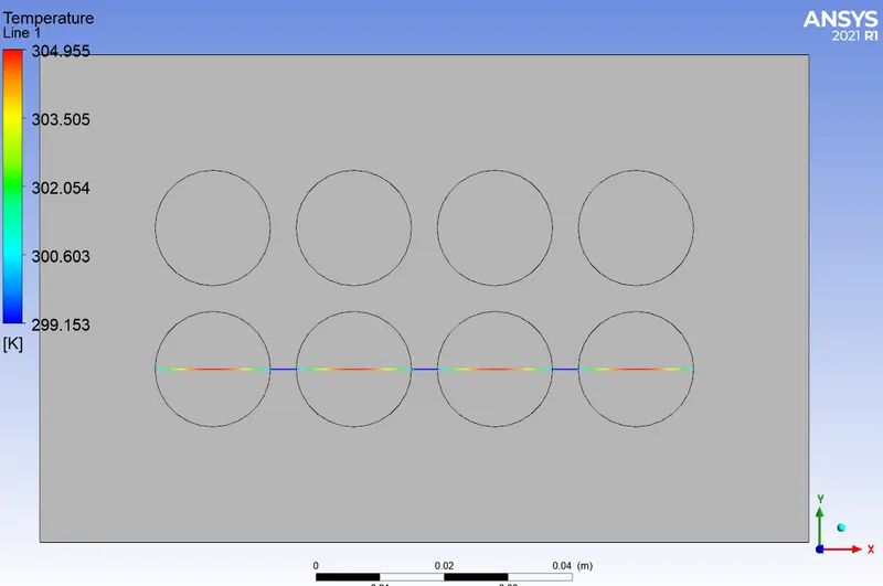
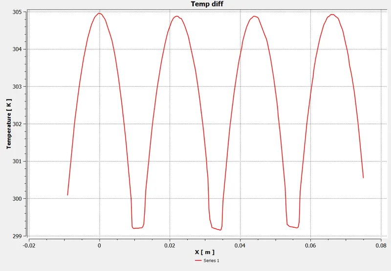
Here, Delta T = 304.955- 299.153 = 5.802.
This is the temperature difference obtained.
Maximum temp obtained at mid plane = 304.966 K
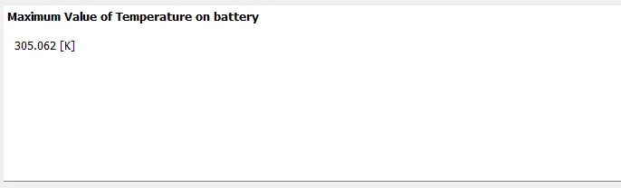
Maximum temp obtained if we consider full battery volume = 305.062 K
CONCLUSION for this model
Here, we can find uniform temperature distribution in all cells of the configuration. Maximum temperature developed in all cells are nearly constant which is around 304.8 K. The value of Delta T is also reduced to around 2.5 K, when using 2 fan instead of one fan with inlet velocity = 10 m/s.
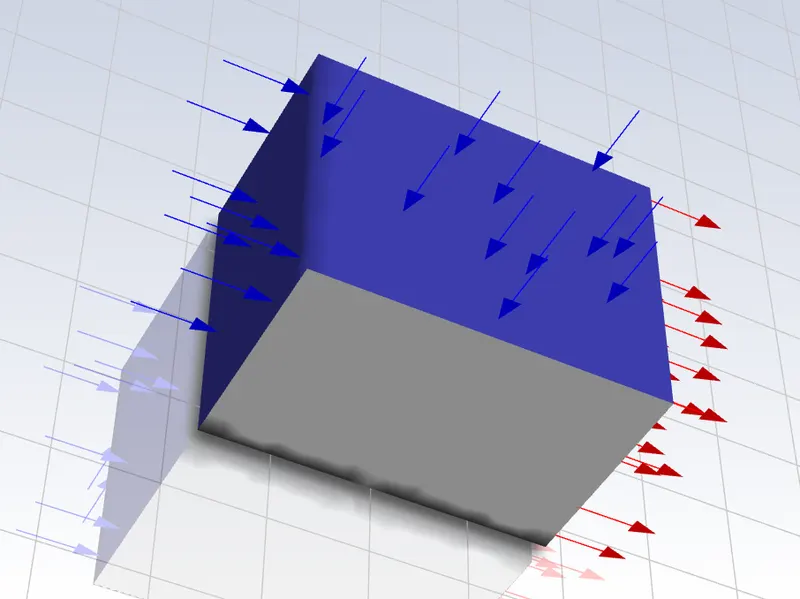
b) Side Inlet,v=10 m/s.
Mesh: case b : Mesh size = 8 mm, body sizing=2 mm
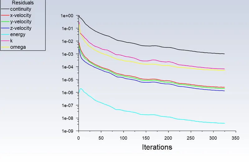
Scaled Residual
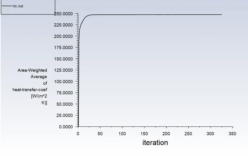
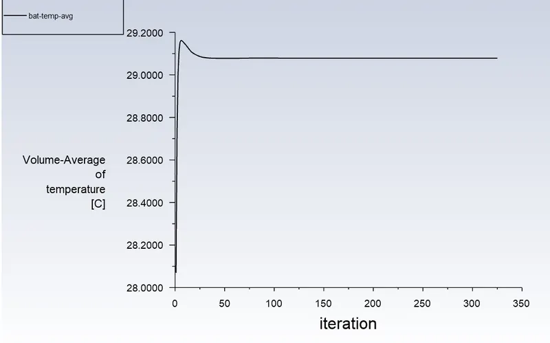
Value = 247.33 W/m2K
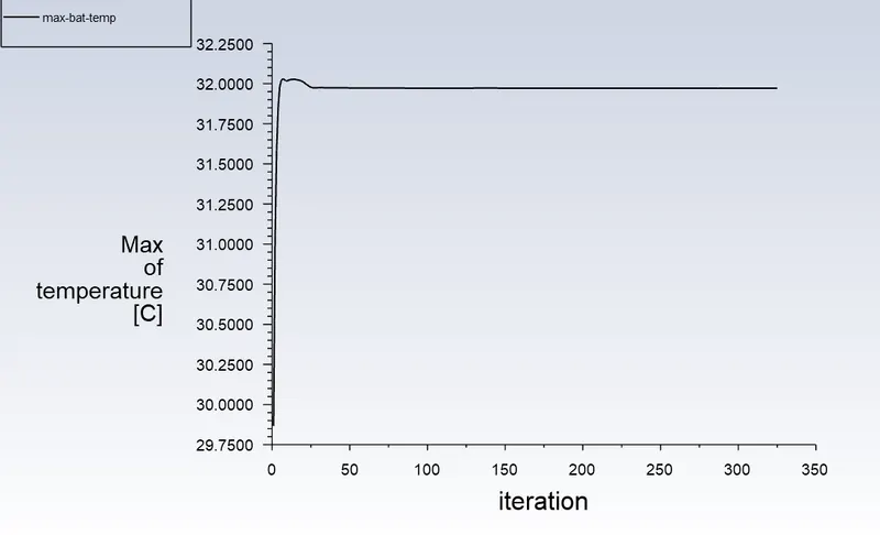
Value = 31.97 *C
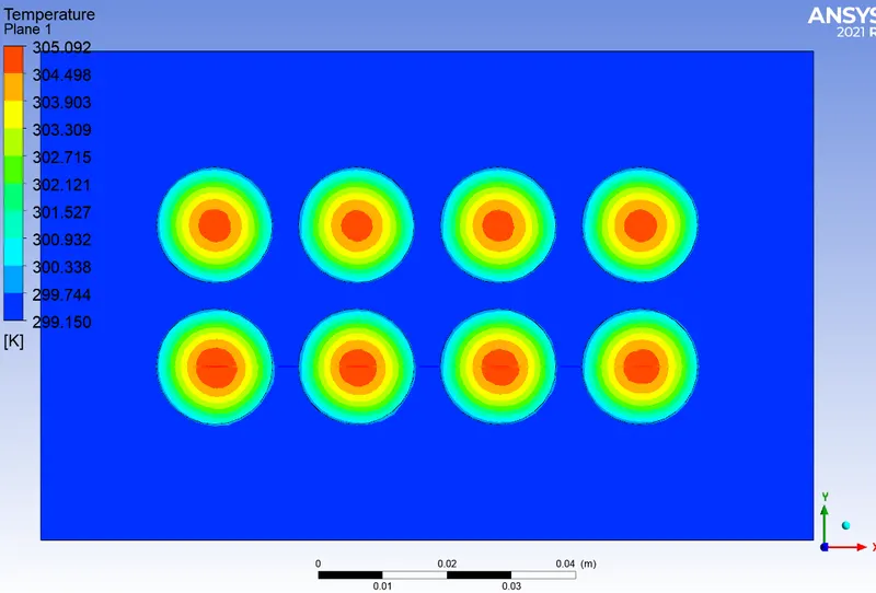
Temperature plot
Temperature chart through cut line
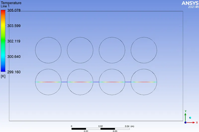
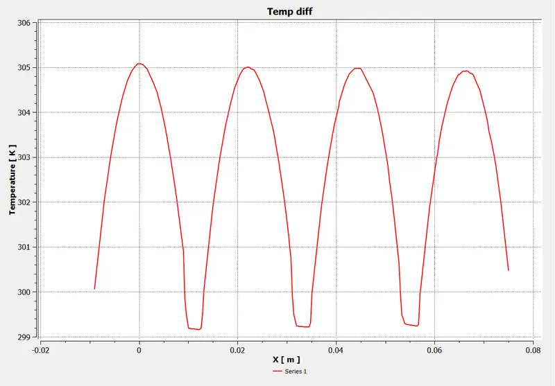
CONCLUSION for this model
The conclusion,values and the plot obtained are similar to above model with top inlet.
Battery model 4 X 6
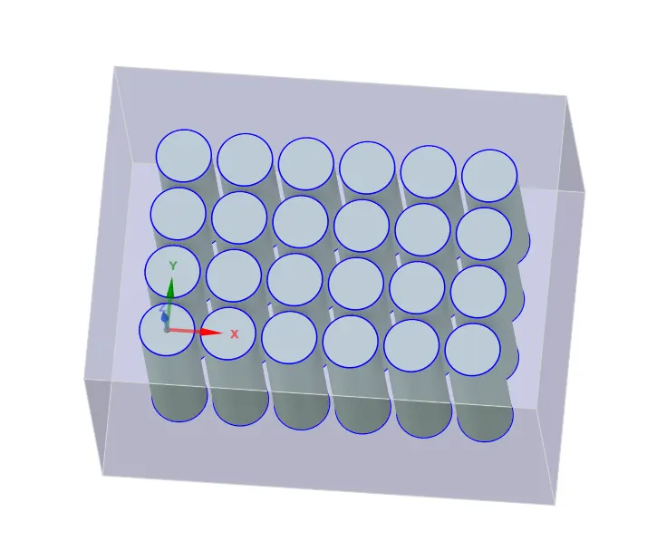
a) Velocity = 3 m/s. One inlet
Scaled Residual
k-omega
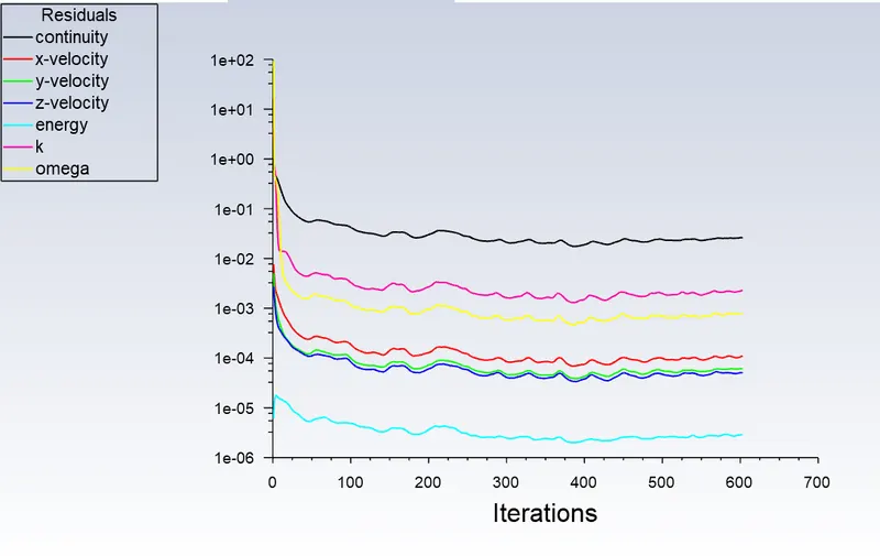
laminar
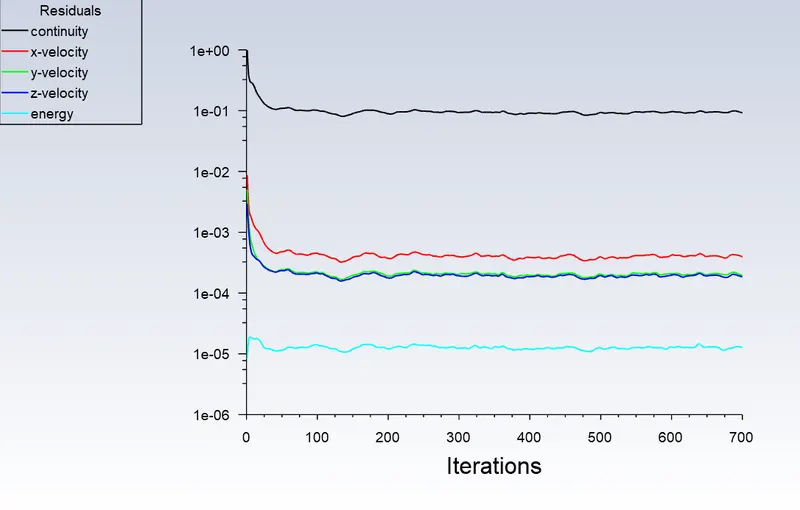
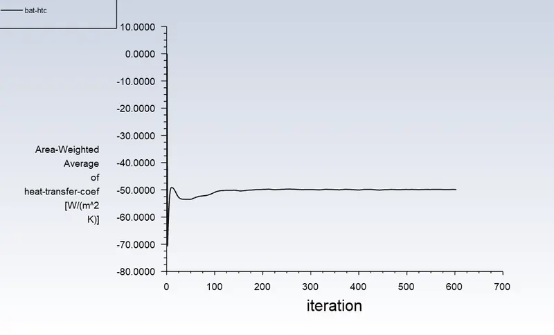
Value = 49.902 W/m2K
k-omega
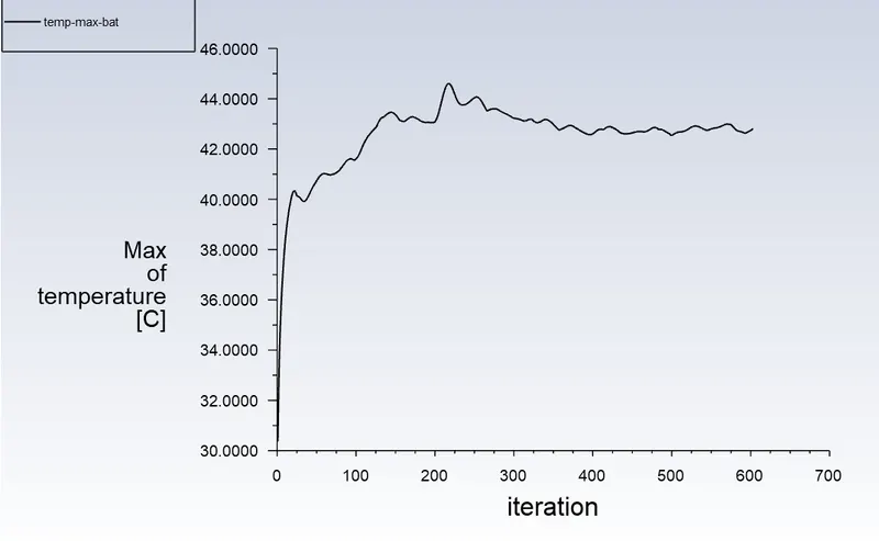
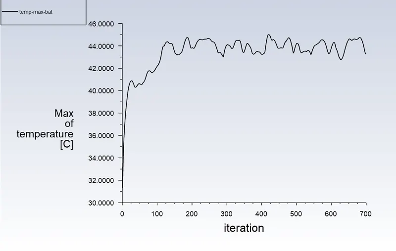
Value = 42.803 *C
laminar
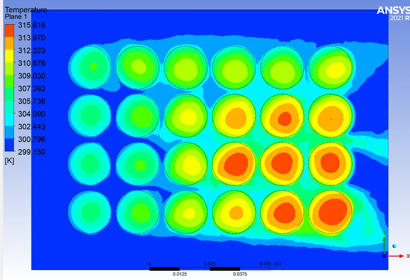
Temperature plot
Temperature chart through cut line
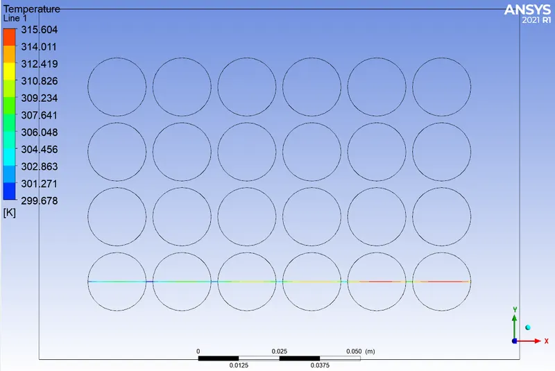
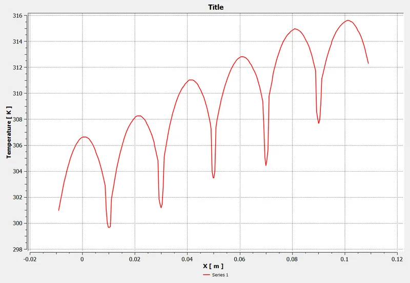
The maximum temperature = 315.616 K (42.5 *C) when the air velocity = 3 m/s.
In literature, they got maximum temperature value = 39 *C.
This may be due to the quality of mesh and different software used for simulation.
Here the temperature is not uniform in all the cells.
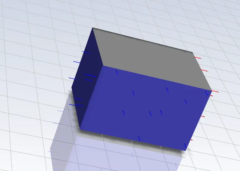
b) Velocity = 10 m/s. Two inlet
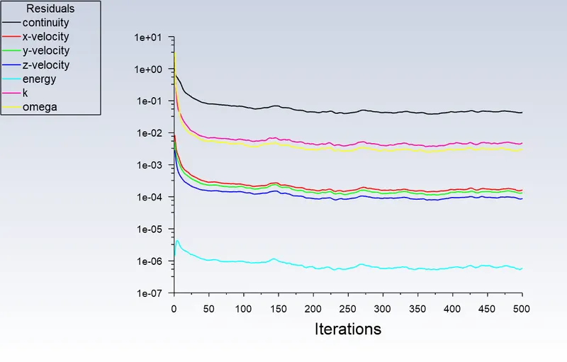
Scaled Residual
k-omega
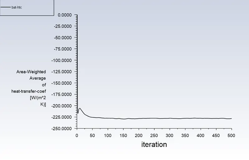
Value = 228.213 W/m2K
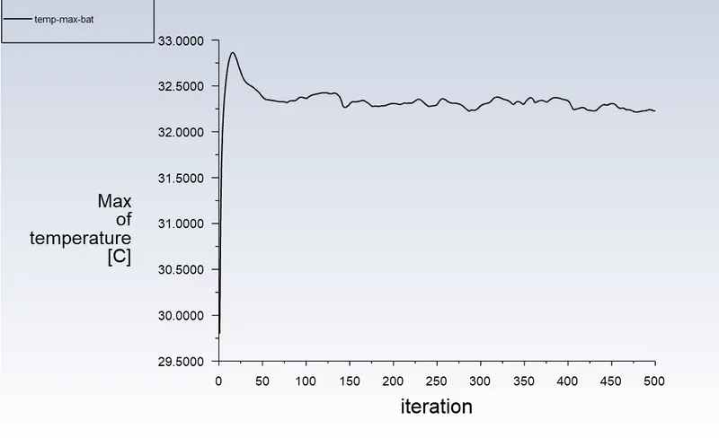
Value = 32.229 *C
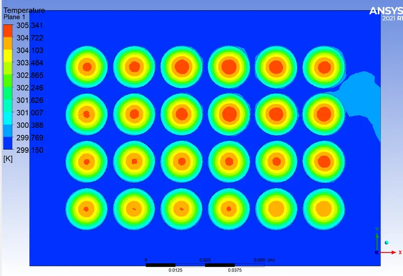
Temperature plot
Temperature chart through cut line
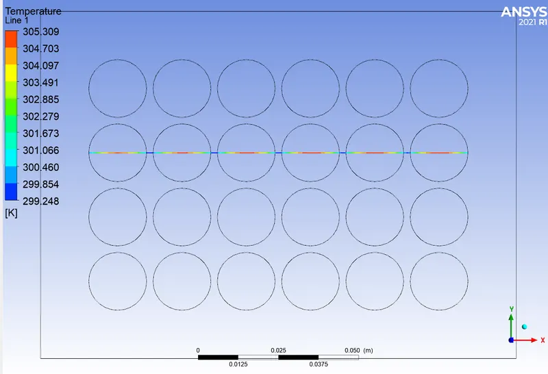
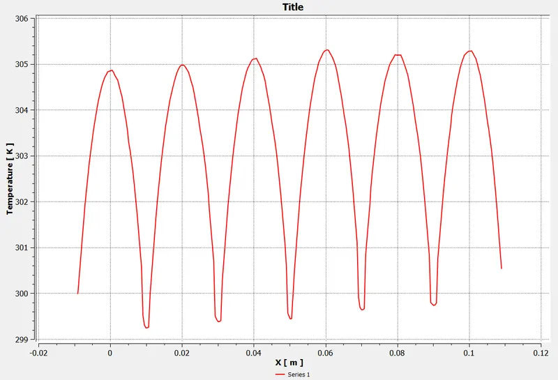
The maximum temperature = 305.341 K (32.15 *C) when the air velocity = 10 m/s with 2 inlet.
Here the temperature distribution is uniform in all the cells. All the cells have same maximum and minimum temperature.
OVERALL CONCLUSION
a) On increasing the inlet velocity, the heat transfer coefficient increases and thus reduces the maximum temperature in the cell.
b) 2 inlet gives more reduction in temperature and also maintains the uniform temperature distribution in all the cells.
c) On increasing the cell spacing for 2 x 4 configuration, the cell temperature decreases by around 3 K
Explain why battery cooling is needed. And give a brief description about various techniques for battery cooling.
EV Batteries have specific operating ranges, which are critical for the battery life and performance. They are designed to operate at ambient temperature, which is between 68°F and 77°F (20°C and 25°C). A better control over the battery temperature improves their performance and life.
- During operation, they can withstand temperature between -22°F and 140°F (-30°C and 50°C)
- During recharges, they can withstand temperatures between 32°F and 122°F (0°C and 50°C)
Batteries generate a lot of heat during operation and their temperature must be brought down within operating ranges. At high temperatures (between 158°F and 212°F, or 70°C and 100°C), thermal runaways can occur, causing a chain reaction that destroys the battery pack.
During fast charges, batteries must be cooled down. This is because the high current going into the battery produces excess heat that must be extracted to preserve the high charging rate and not overheat the battery.
They sometimes also need to be heated up when the temperature is too low or to boost performances. For example, cells cannot be charged below 32°F (0°C). Or, companies like Tesla offer battery preheating in some models to reach high performances, going from 0 to 60 mph in less than 2 seconds.
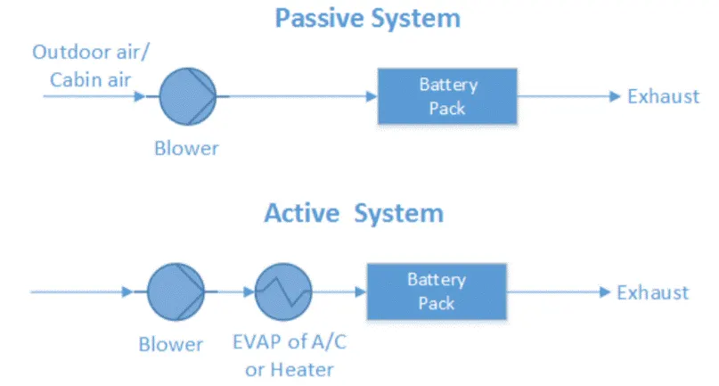
i) Air cooling and heating: air systems use air as the thermal medium. The intake air could be direct either from atmosphere or from the cabin (passive) and could also be conditioned air after a heater or
evaporator of an air conditioner (active)
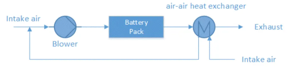
In addition, to make better use of this system, heat from the exhaust can be extracted and re-used whenever the battery needs to be heated through an air-air heat exchanger.
Evaluation: high reliability, low cost, low maintenance, but poor thermal management. At the same flow rate, the volume of air is much higher than volume of water, but the heat transfer coefficient is much lower than that of water, meaning it will require more space and energy for air to dissipate as much energy as water. At higher discharge current rate, the difference in temperature between different cells could reach 5 degree C, which could be more than the difference between the cell temperature and the ambient temperature. So, if thermal runaway starts in one cell, with an air cooling system, the system won't be able to prevent all the cells from catching fire.
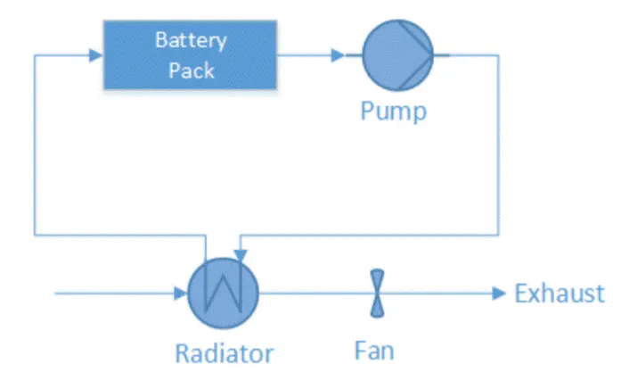
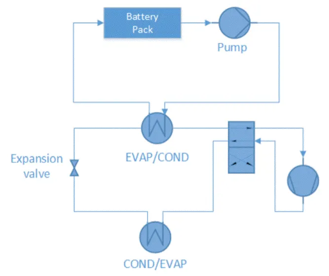
ii) Liquid Cooling and Heating: By different heat-sinks for cooling, liquid systems can also be categorized into either passive systems or active systems. In passive liquid system (figure on the left below), the heat-sink for cooling is a radiator. This system has no ability to heat. Heat transfer fluid is circulated by the pump within a closed system. The circulating fluid absorbs heat from battery pack and releases heat via a radiator. The cooling power depends strongly on the temperature between ambient air and battery. Fans behind the radiator can improve the cooling performance, but if ambient air is higher than the battery temperature or the difference between them is too small, the passive liquid system becomes ineffective.
In an active liquid system (figure on the right below), there are two loops. The upper is called the primary loop and the lower the secondary loop. The primary loop is similar to the loop in a passive liquid system, where the heat transfer fluid is circulated by pump. The secondary loop is actually an air conditioning loop (A/C loop). The upper heat exchanger instead of being a radiator works as an evaporator (EVAP) for cooling operation and connects both loops. During heating operation, the 4 way valve will be switched, and the upper heat exchanger works as a condenser (COND) and the lower heat exchanger works as an evaporator.
iii) Direct Refrigerant Cooling and Heating: Similar to active liquid systems, a direct refrigerant system (DRS) consists of an A/C loop, but DRS uses refrigerant directly as heat transfer fluid circulating through the battery pack.
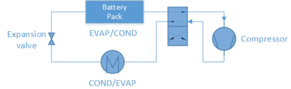
Evaluation: much more efficient than liquid cooled systems since the refrigerant is directly used to cool the system, as opposed to a liquid absorbing heat and then being cooled in order to cool the system. However, because a refrigerant loses its cooling ability everytime it is recirculated, it needs to be replaced once in a while.
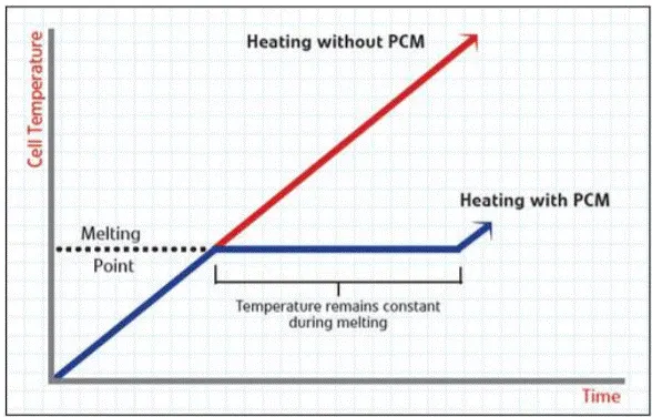
iv) PCM: a phase change material used as a conductor that will transition between solid and liquid. When the battery gets too hot, the PCM will absorb the heat. Phase change only happens at constant temperature, so once the PCM has absorbed maximum latent heat, all the heat energy from the pack will make the PCM melt and change to liquid. Temperature remains constant during a phase change, so this procedure will delay the pack from increasing its temperature any further. Once the heat is transferred to the surroundings, the PCM returns back to its solid phase
Evaluation: high thermal conductivity so if one cell fails, thermal runaway will not propagate because the PCM-graphite matrix absorbs and spreads the heat quickly