Week 9 - Parametric study on Gate valve.
Introduction
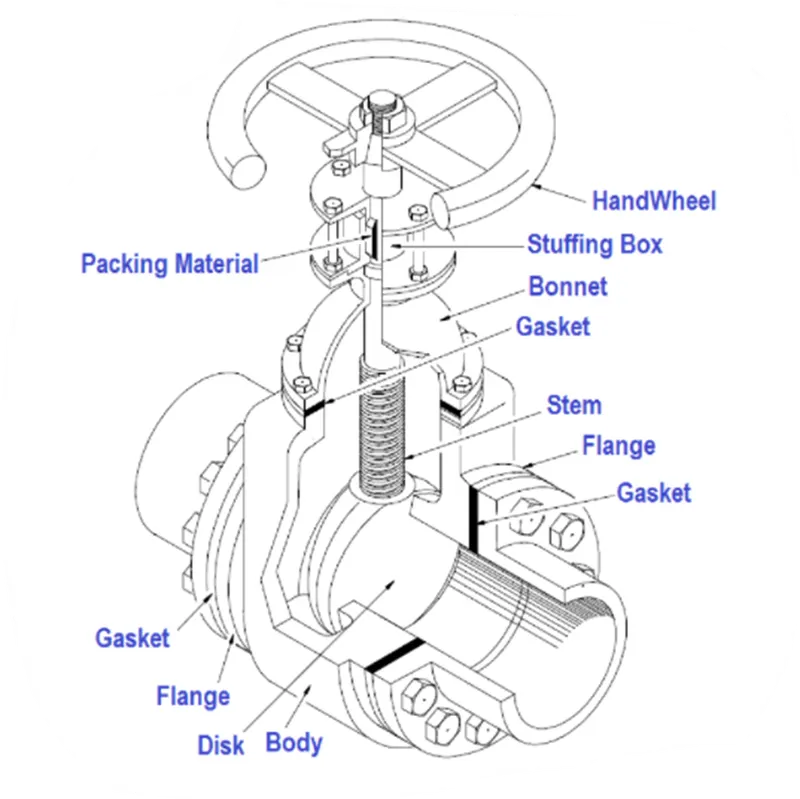
A gate valve, also known as sluice valve is a valve that opens by lifting a barrier(gate) out of the path of the fluid. gate valves require very little space along the pipe axis and hardly restrict the flow of fluid when the gate is fully opened. the gate faces can be parallel but are most commonly wedge-shaped (in order to be able to apply pressure on the ceiling surface).
Parametric study
One of the best ways to get value out of your simulation is to do parametric analysis. With very little marginal work a completed model can be parametrized to simulate scenarios limited only by your computational time and resources.
As you move forward in your design, you can access the impact that changing certain parameters can have on the design. The parameters can include dimensional parameters parametric study allows you to nominate parameters for evaluation, define the parameter range, specify the design constraints and analyze the results of each parameter variation.
Case setup
- Geometry
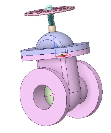
- Import geometry In SpaceClaim.
- Pull pipe to 700mm in both the sides.
- Import geometry In SpaceClaim.
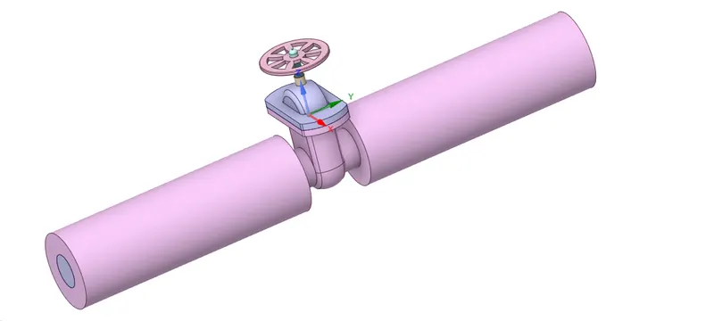
-
- Extract fluid volume.
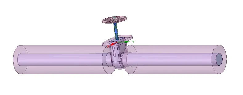
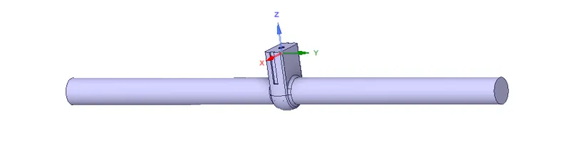
- Update volume body in context.
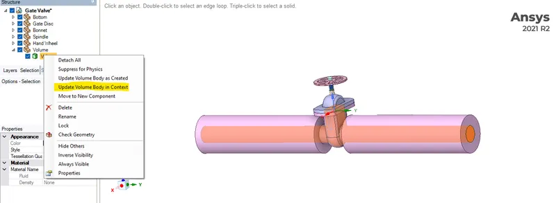
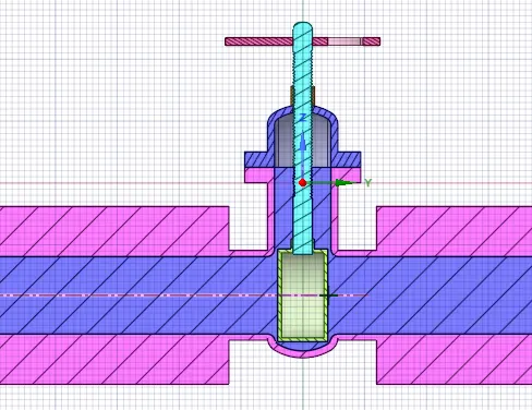
- Extract fluid volume.
Create parameterization group.
- Hide all components except 'spindle and gate disc'.
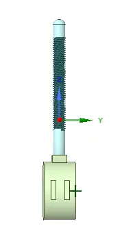
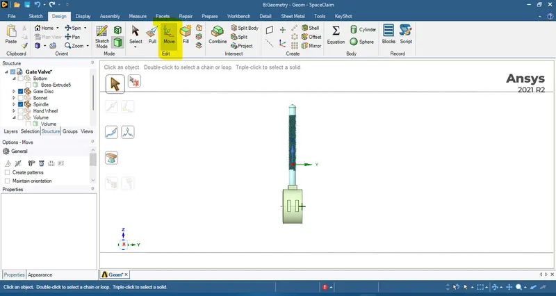
- select move tool from design.
- now select body selection.
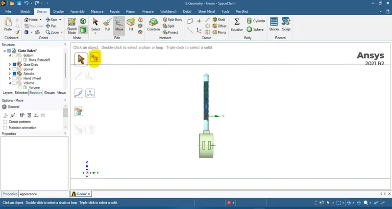
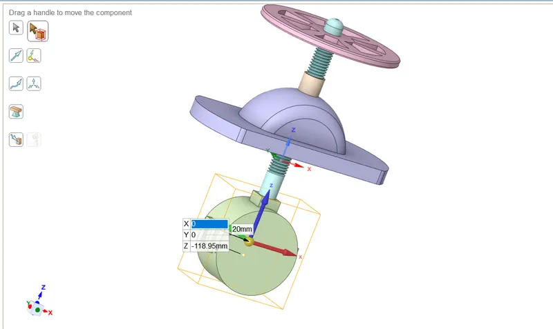
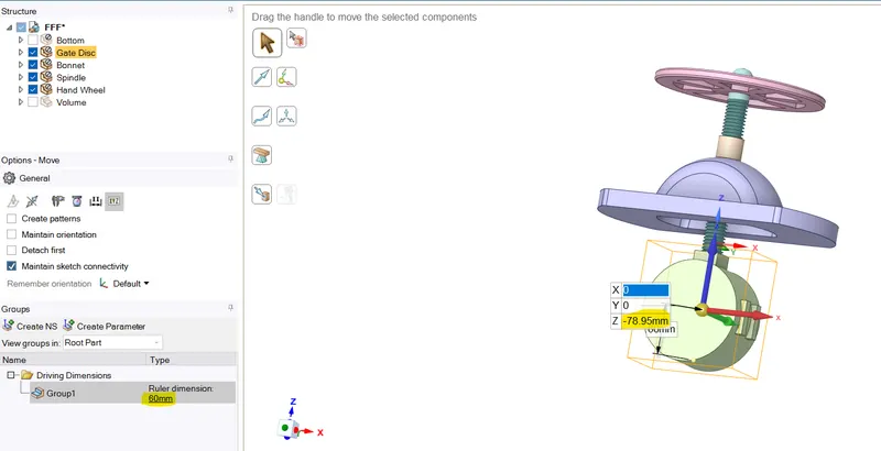
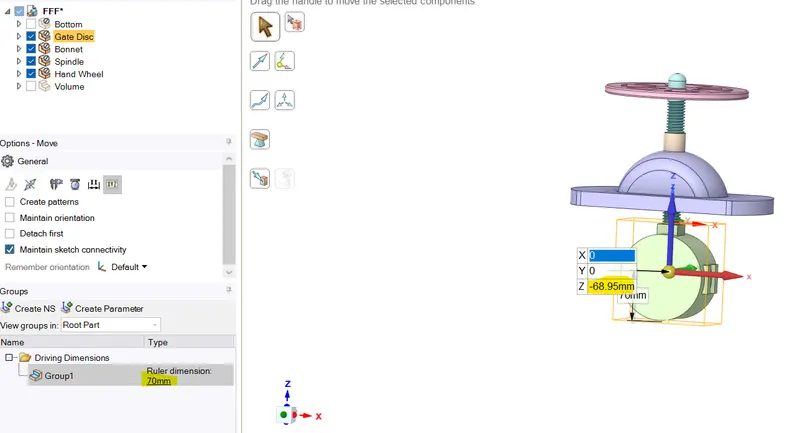
- drag the gate disc a little bit in z-direction now enter any value e.g., 10mm.
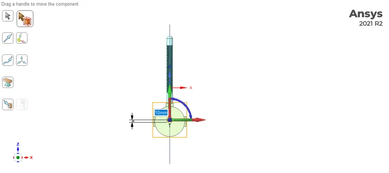
- Go to group and click on create parameter.
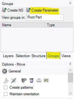
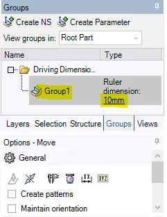
- Now parameter has been created. where we can change the dimension.
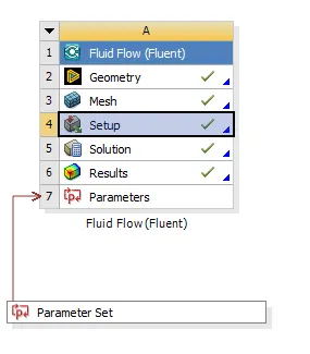
- Meshing
Mesh the fluid volume of gate valve.
baseline mesh
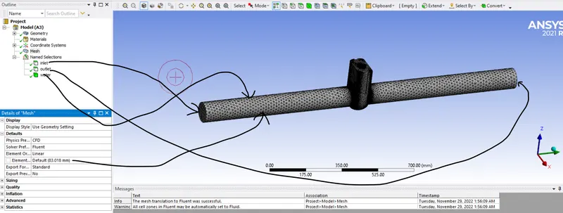
For 10 mm lift
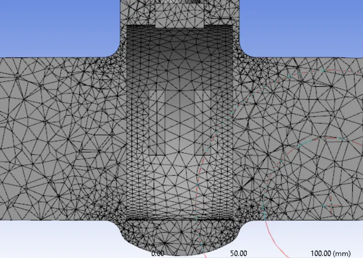
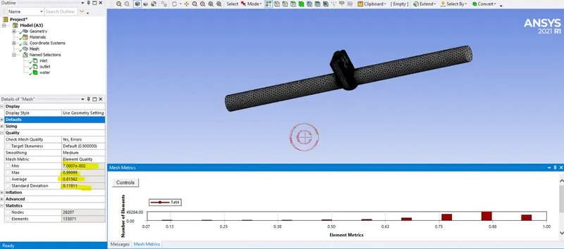
Check the element quality
Setup
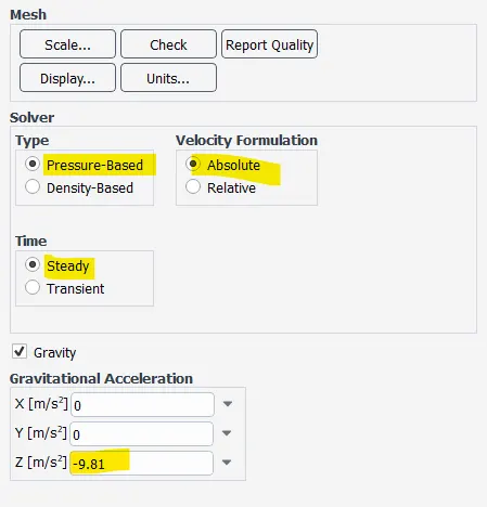
- general setup
- Analysis type: steady state
- solver: pressure based
- Velocity formulation: absolute
- gravity enabled with the value of -9.81`m/s^2` in z-direction.
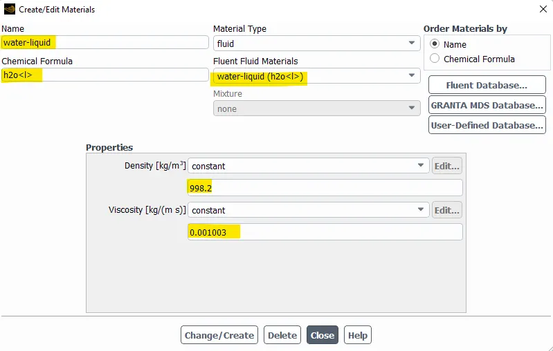
- material selection
- material: water-liquid(`H_2O`)
- Density: 998.2`[Kg]/m^3`
- viscosity: 0.001003`[Kg]/[m*s]`
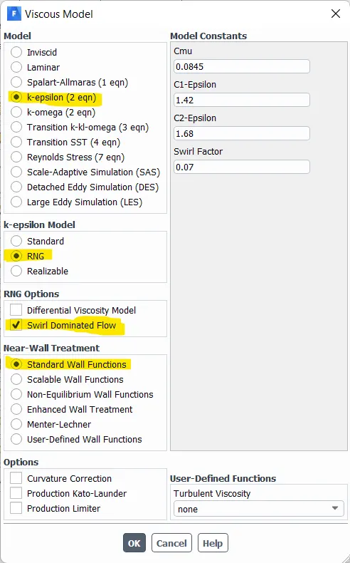
- viscous model
- Model: K-epsilon
- K-epsilon model: RNG, swirl dominated flow
- near wall treatment: Standard wall function
-
- Boundary condition
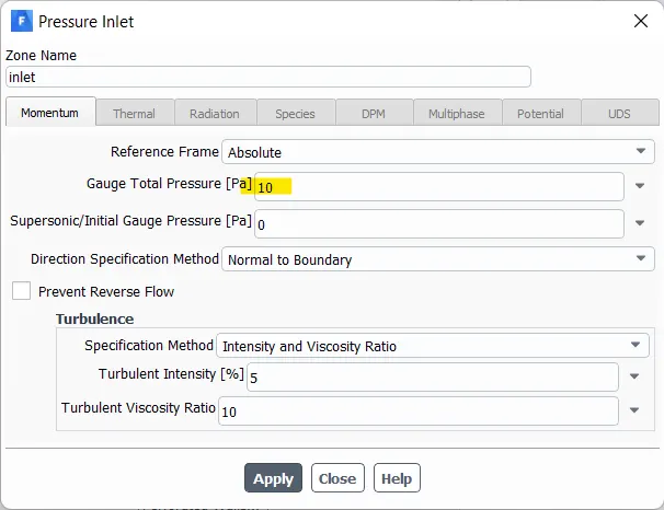
- inlet
- type: pressure inlet
- Guage total pressure: 10Pa
- inlet
- outlet
- type: pressure outlet
- Guage total pressure: 0Pa
- wall
- type: wall
- wall motion: stationary wall
- shear condition: no slip
- outlet
- Boundary condition
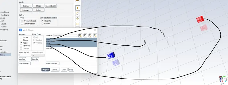
Create a plane before and after the gate valve to get the average pressure at that cross section
- Create Report definition for
- mass flow rate outlet
- pressure at inlet
- pressure at outlet
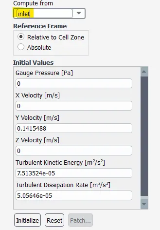
- Initialization: standard initialization from inlet
Solution method
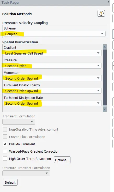
- Run simulation for 300 to 500 iterations.
Result
a) 10mm opening
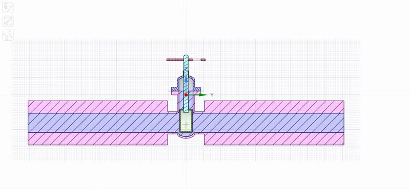
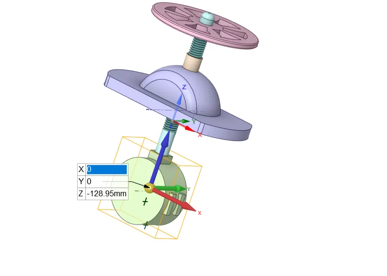
Cordinates shown below
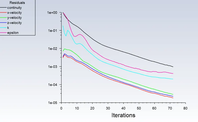
Scaled Residual
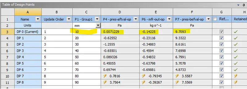
Mass flow rate at outlet
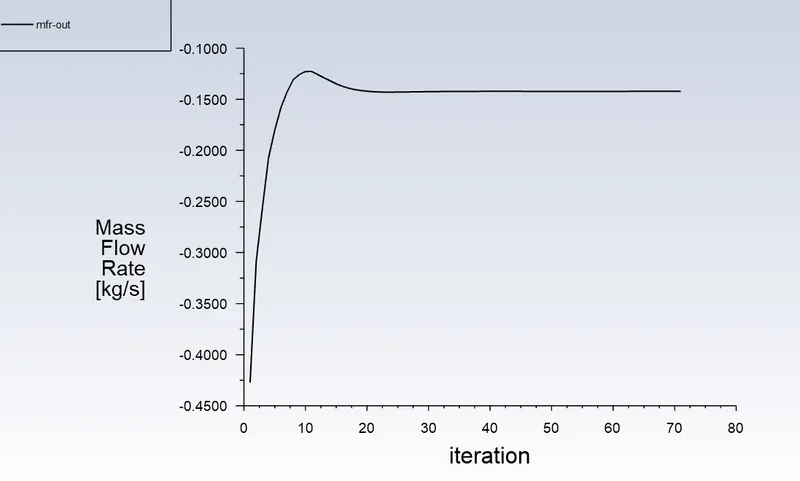
Value = 0.14224 kg/s
Pressure at a plane before gate valve
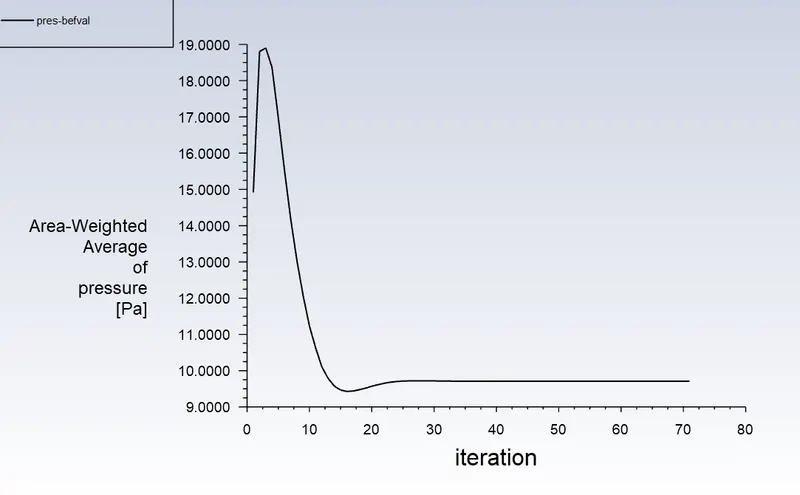
Value = 9.7093 Pa
Pressure at a plane after gate valve
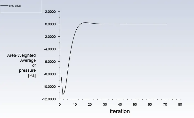
Value = 0.0071228 Pa
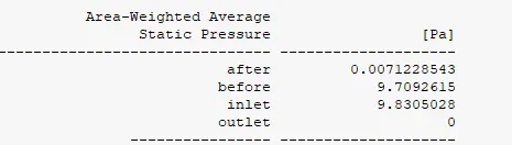

These values are same as the displayed parameter output
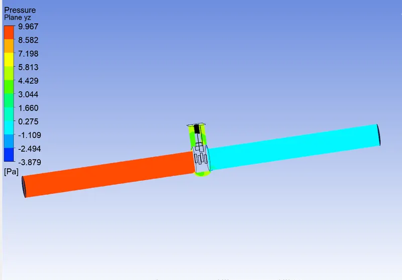
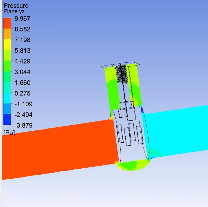
CFD post
Pressure plot
Velocity plot
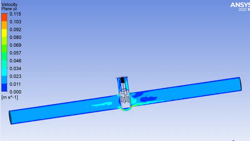
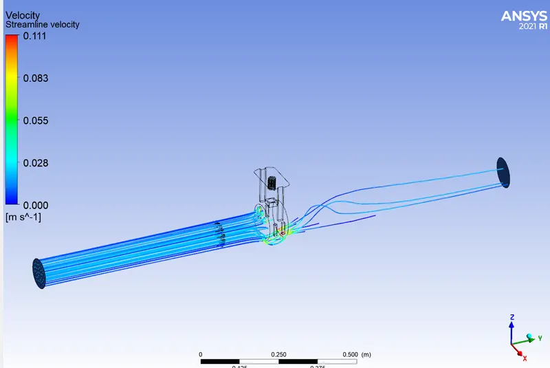
Video file: FFF10.wmv
Result
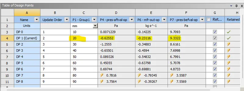
b) 20mm opening
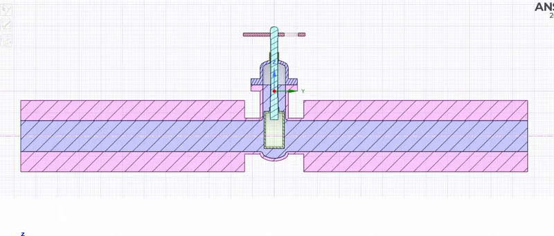
Cordinates shown below
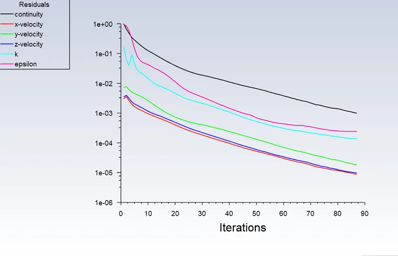
Scaled Residual
Mass flow rate at outlet
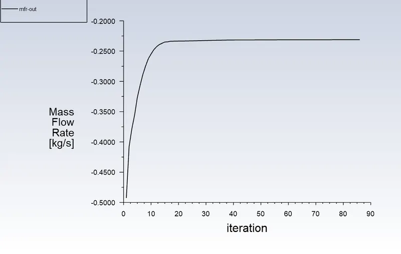
Value = 0.23116 kg/s
Pressure at a plane before gate valve
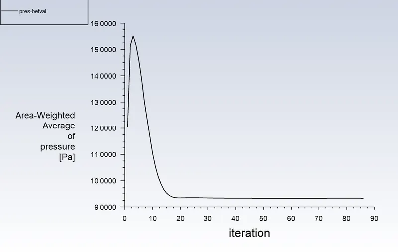
Value = 9.33216 Pa
Pressure at a plane after gate valve
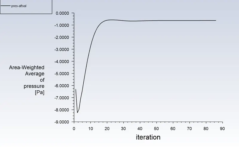
Value = 0.62552144 Pa
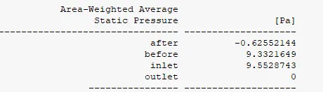

These values are same as the displayed parameter output
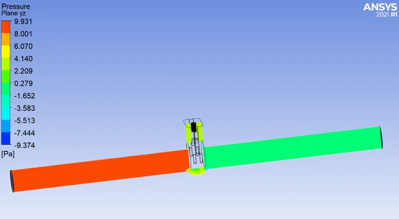
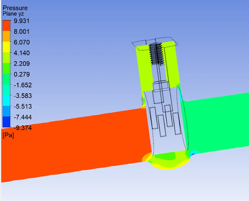
CFD post
Pressure plot
Velocity plot
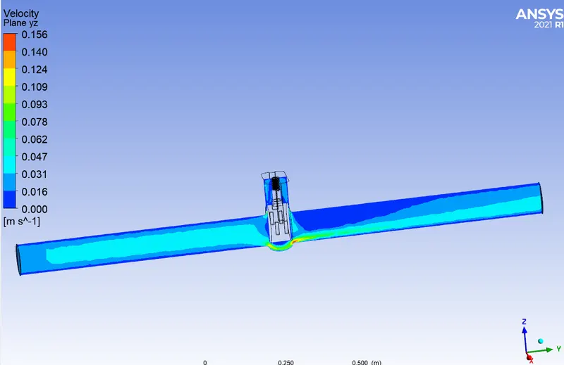
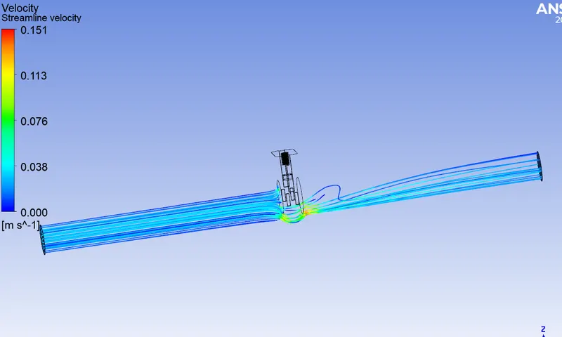
Video file: FFF20.wmv
Result
c) 30mm opening
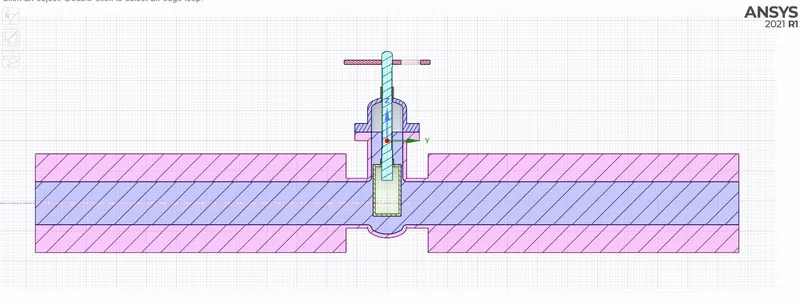
Cordinates shown below
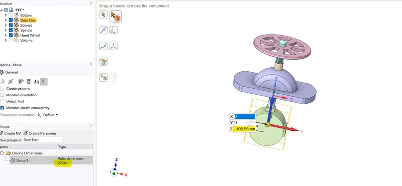
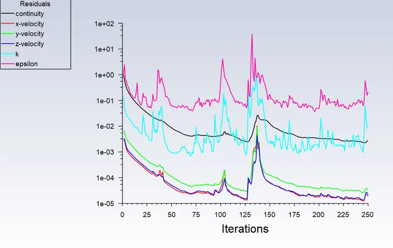
Scaled Residual
Mass flow rate at outlet
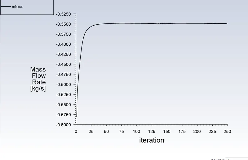
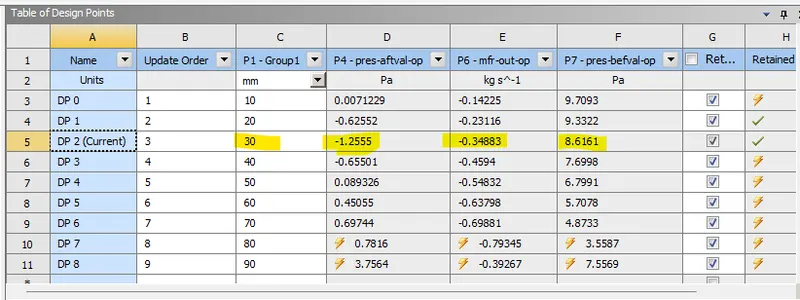
Value = 0.3488 kg/s
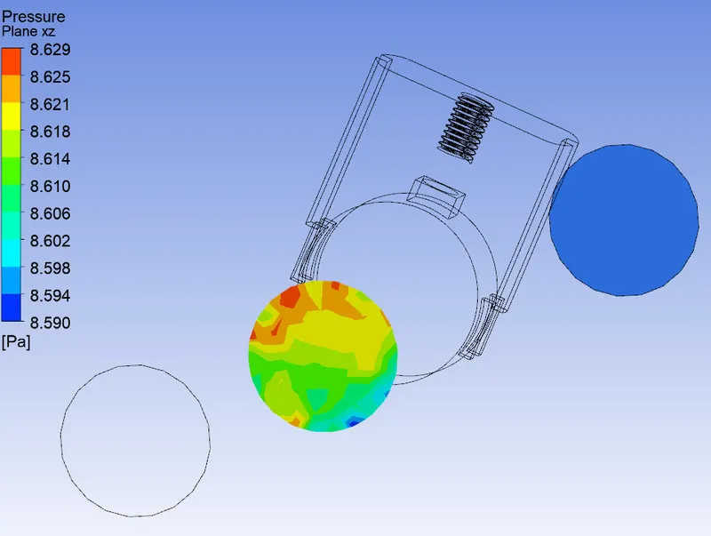
Pressure at a plane before gate valve
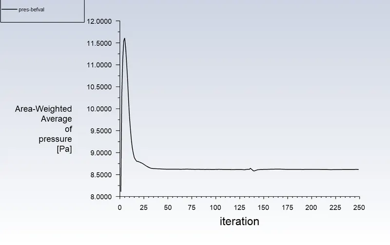
Value = 8.61607 Pa
Pressure at a plane after gate valve
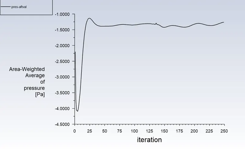
Value = 1.2555 Pa
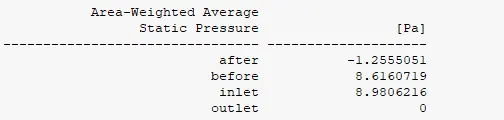

These values are same as the displayed parameter output
CFD post
Pressure plot
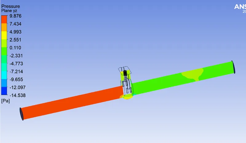
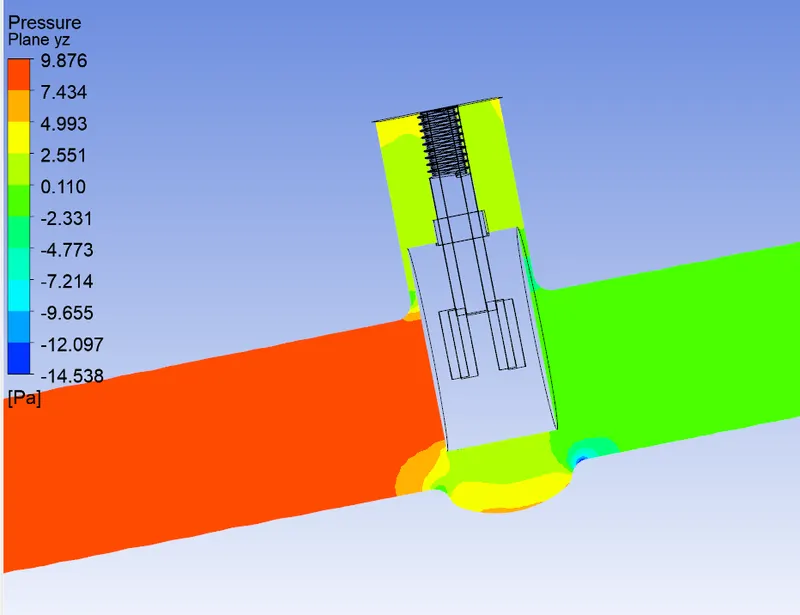
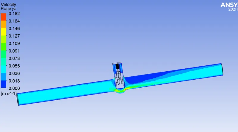
Velocity plot
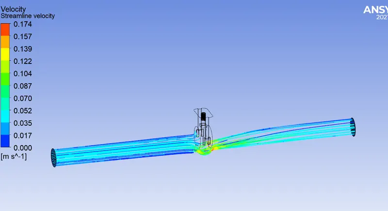
Video file: FFF30.wmv
Result
d) 40mm opening
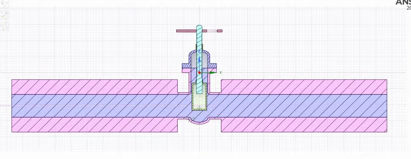
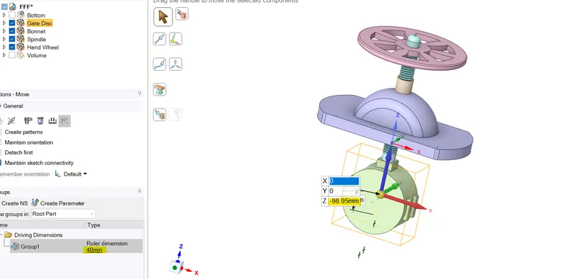
Cordinates shown below
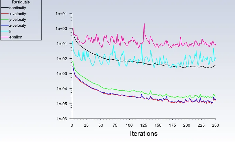
Scaled Residual
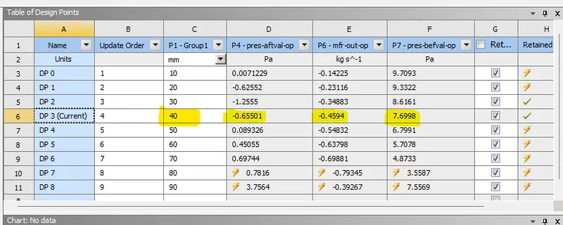
Mass flow rate at outlet
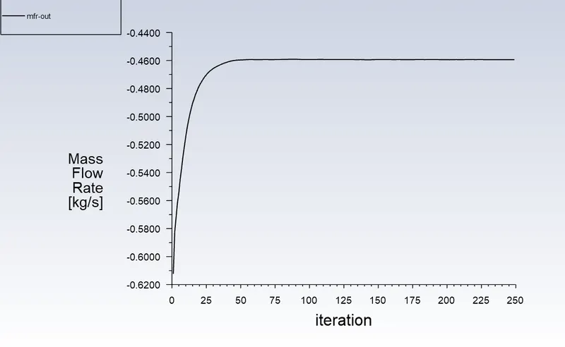
Value = 0.4594 kg/s
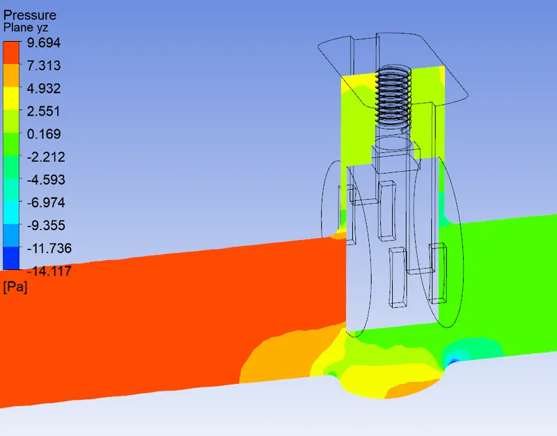
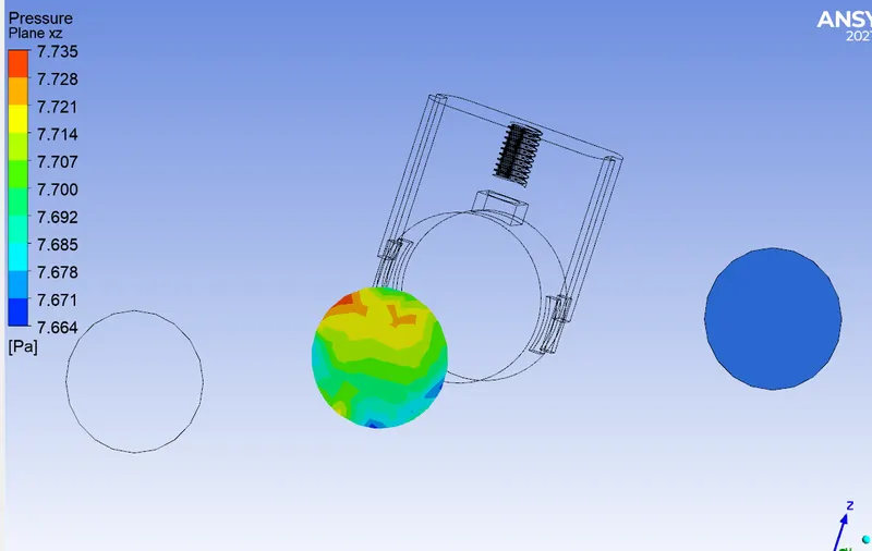
Pressure at a plane before gate valve
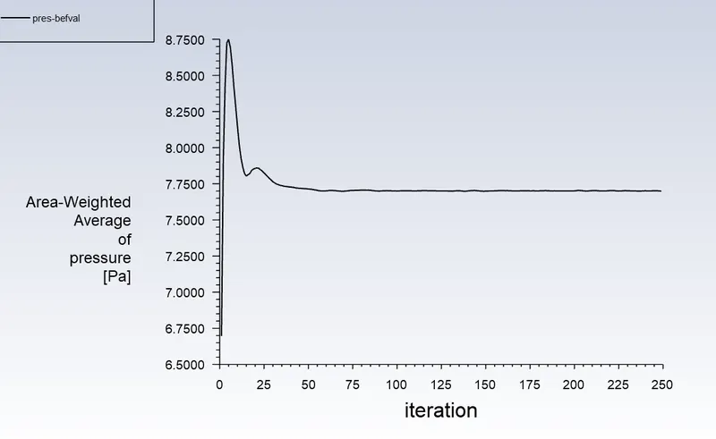
Value = 7.6998 Pa
Pressure at a plane after gate valve
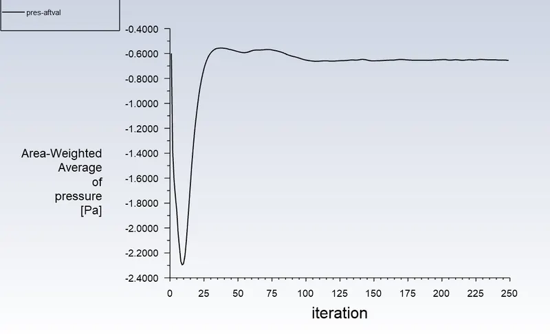
Value = 0.65500656 Pa
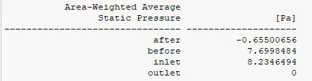

These values are same as the displayed parameter output
CFD post
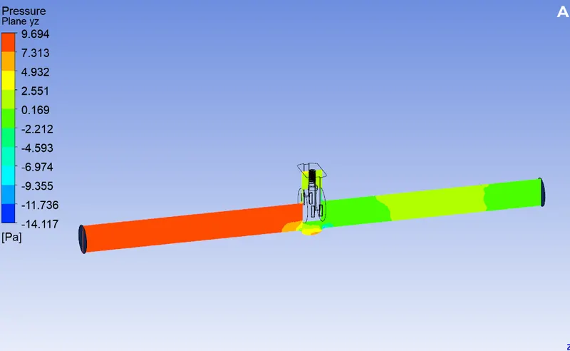
Pressure plot
Velocity plot
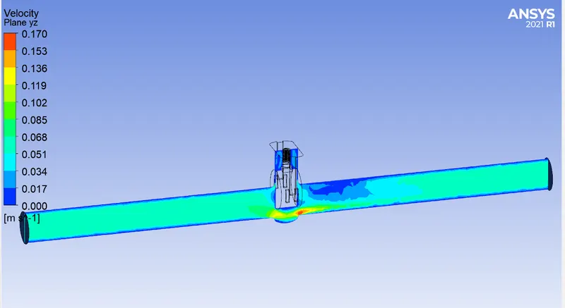
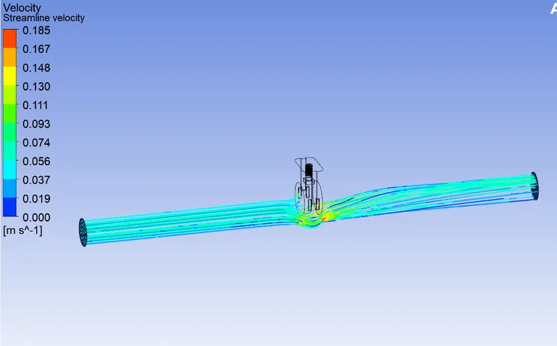
Video file: FFF40.wmv
Result
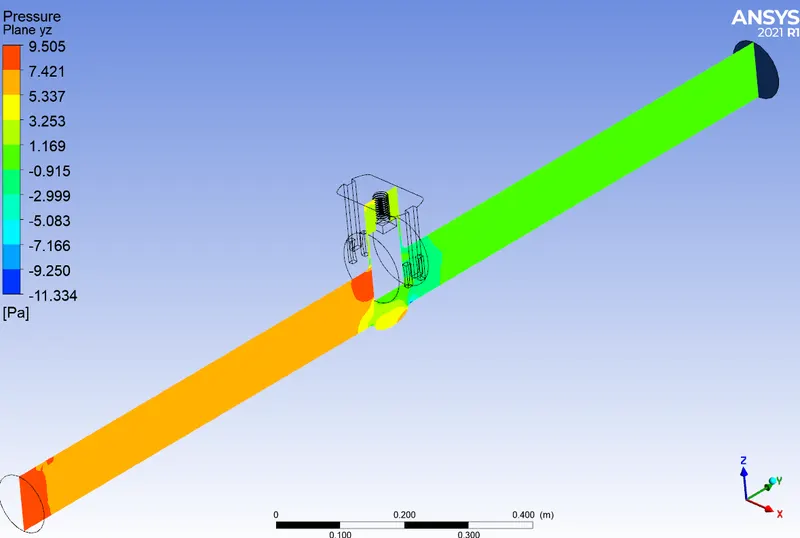
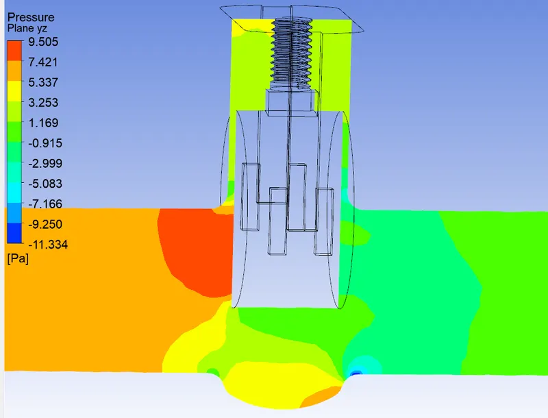
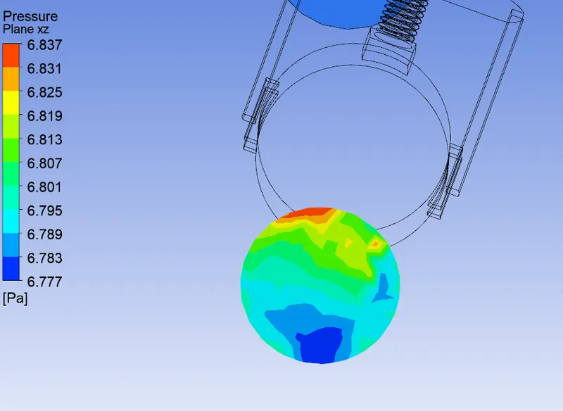
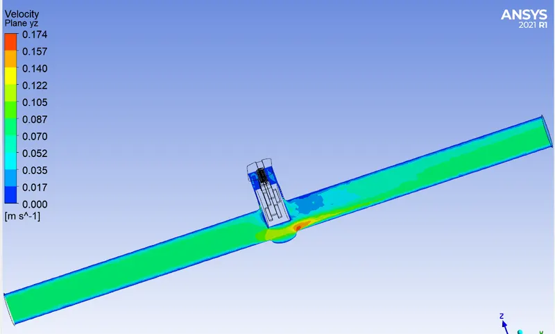
e) 50mm opening
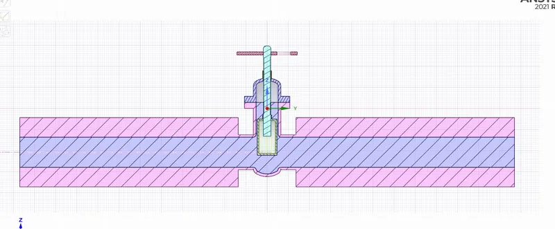
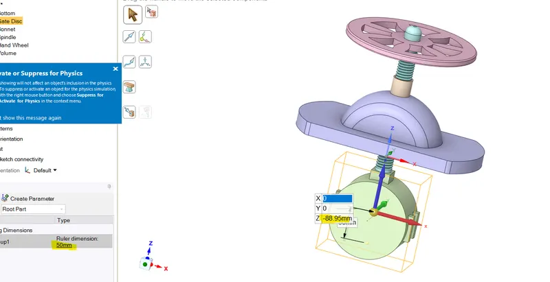
Cordinates shown below
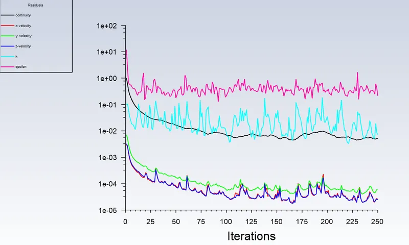
Scaled Residual
Mass flow rate at outlet
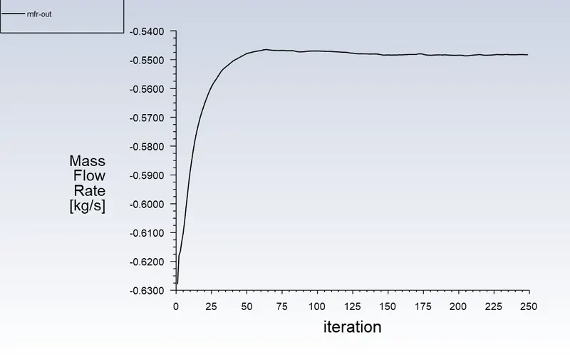
Value = 0.548322 kg/s
Pressure at a plane before gate valve
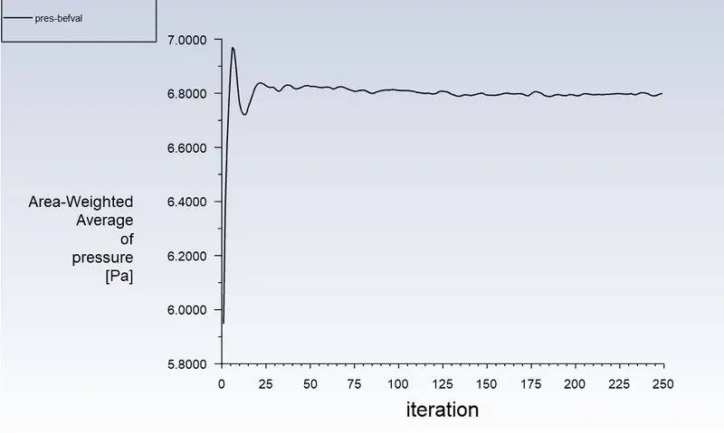
Value = 6.7991 Pa
Pressure at a plane after gate valve
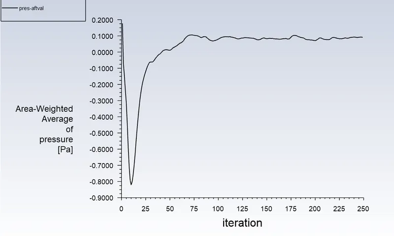
Value = 0.089326489 Pa
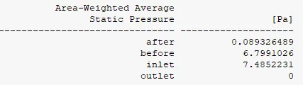

These values are same as the displayed parameter output
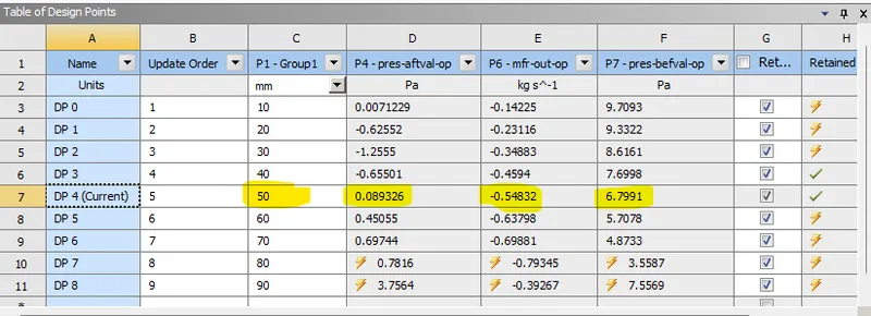
CFD post
Pressure plot
Velocity plot
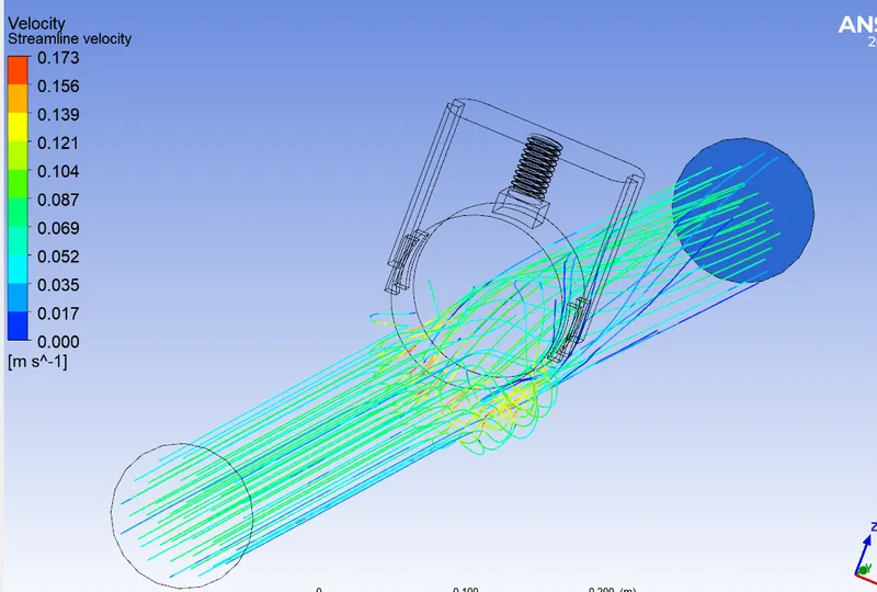
Video file: FFF50.wmv
Result
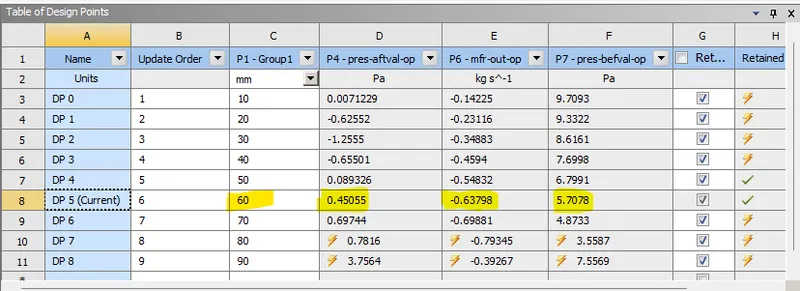
f) 60mm opening
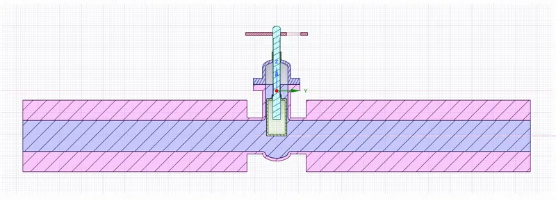
Cordinates shown below
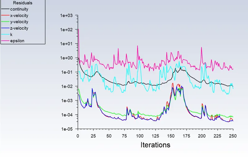
Scaled Residual
Mass flow rate at outlet
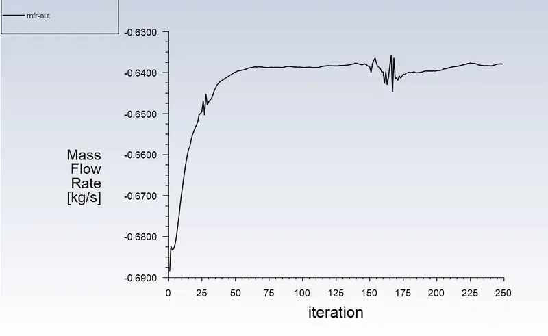
Value = 0.63798 kg/s
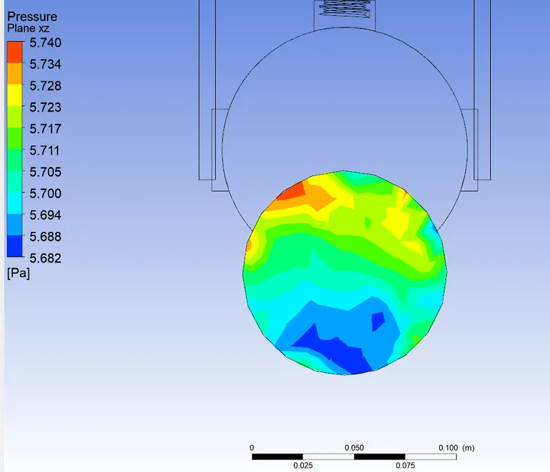
Pressure at a plane before gate valve
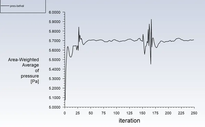
Value = 5.7078 Pa
Pressure at a plane after gate valve
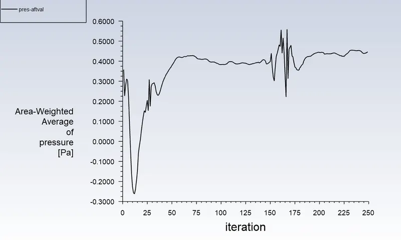
Value = 0.45055 Pa
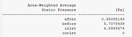

These values are same as the displayed parameter output
CFD post
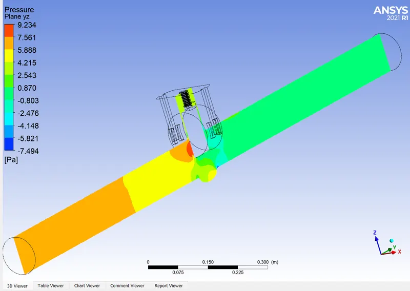
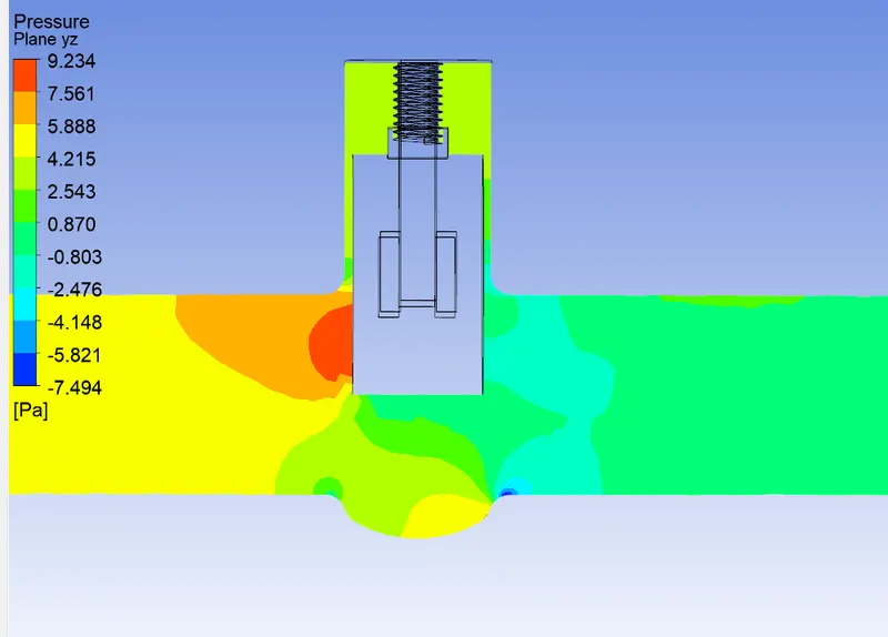
Pressure plot
Velocity plot
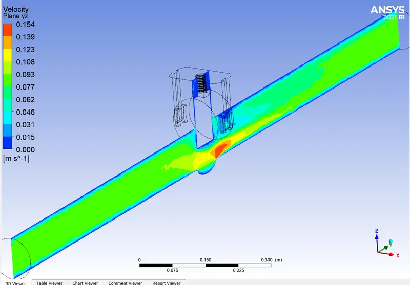
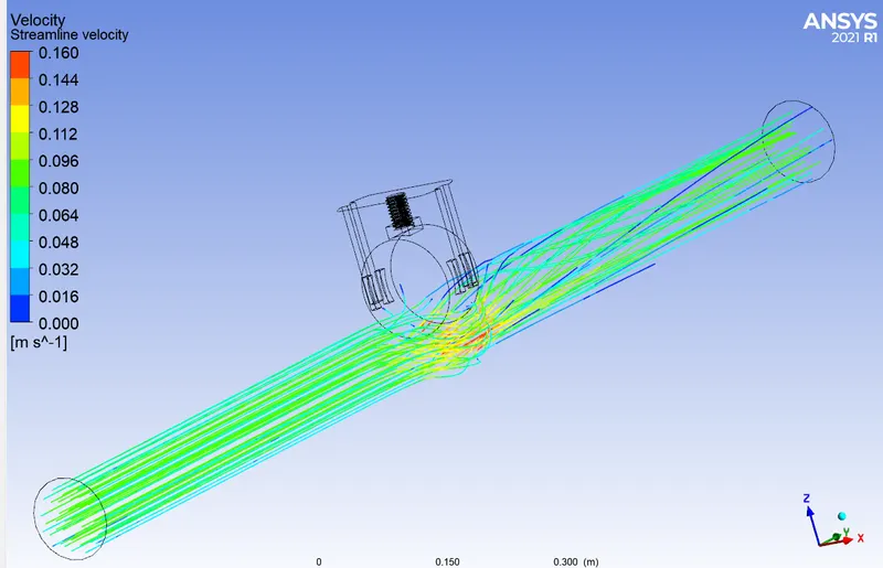
Video file: FFF60.wmv
Result
g) 70mm opening
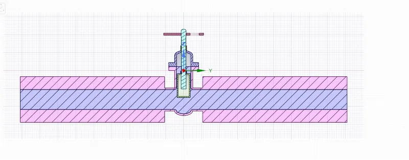
Cordinates shown below
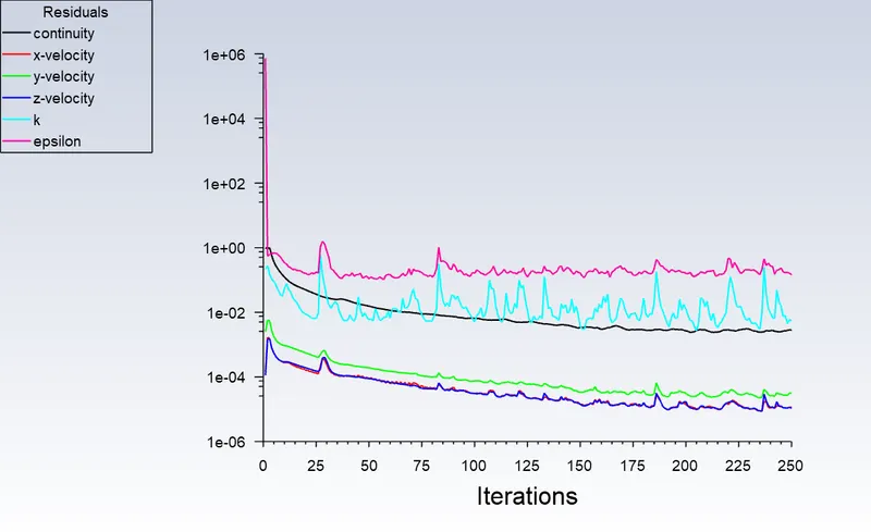
Scaled Residual
Mass flow rate at outlet
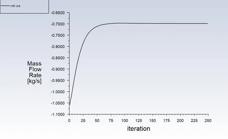
Value = 0.6988 kg/s
Pressure at a plane before gate valve
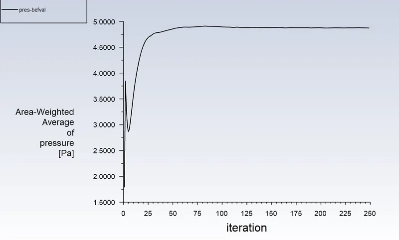
Value = 4.87327 Pa
Pressure at a plane after gate valve
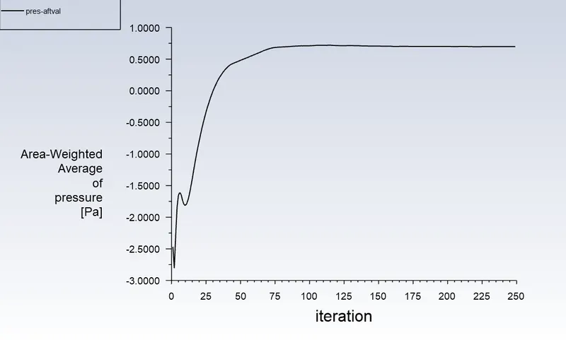
Value = 0.69743 Pa
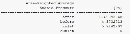

These values are same as the displayed parameter output
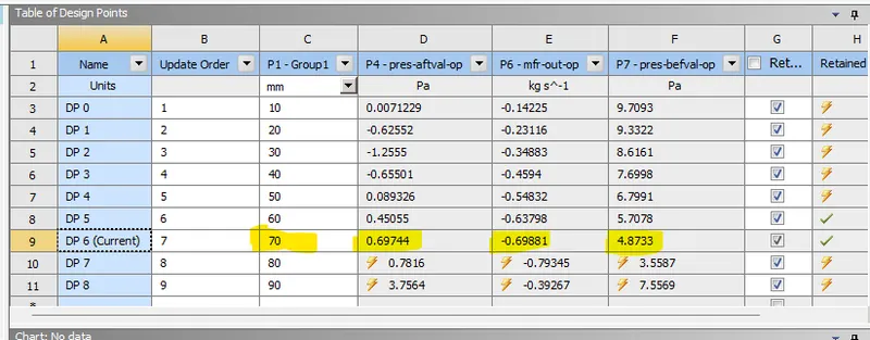
CFD post
Pressure plot

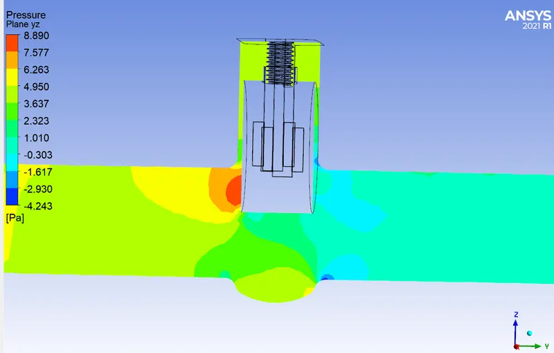
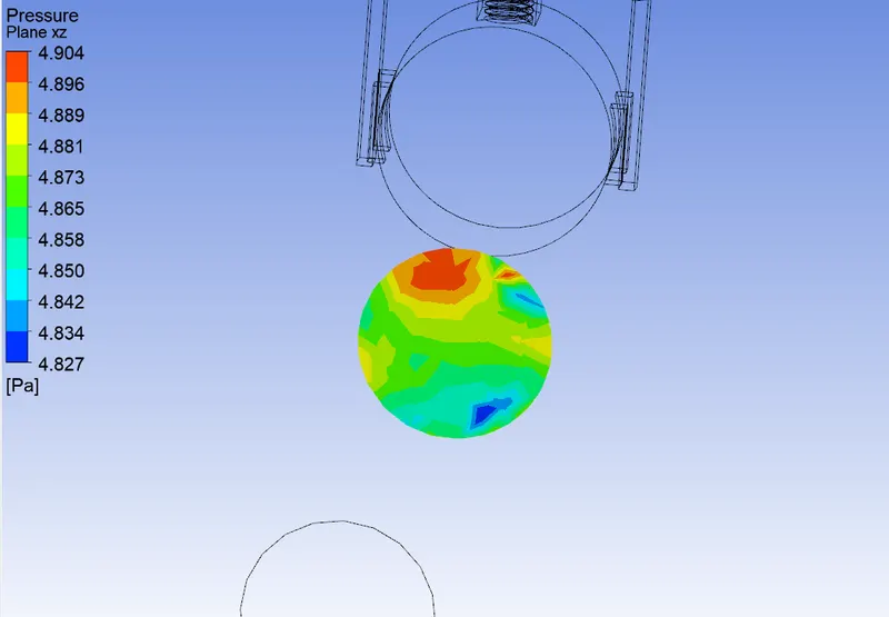
Velocity plot
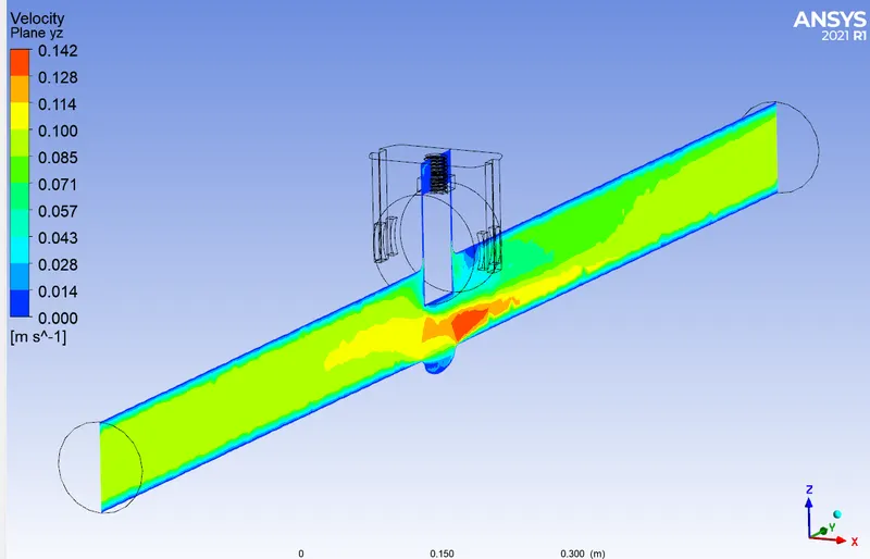
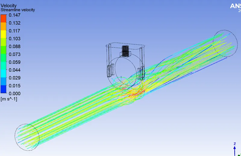
Video file: FFF70.wmv
Result
h) 80mm opening
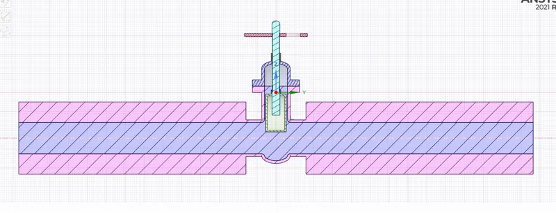
Here the spindle should be moved upwards
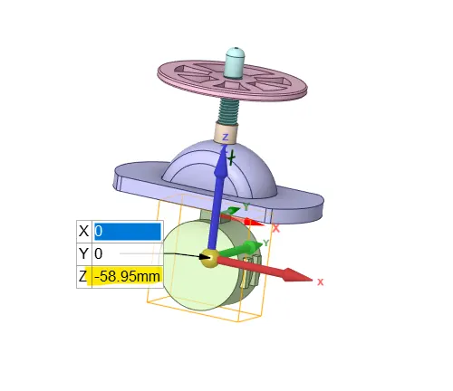
Cordinates shown below
Scaled Residual
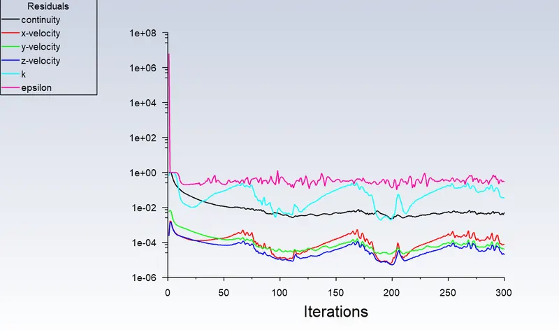
Mass flow rate at outlet
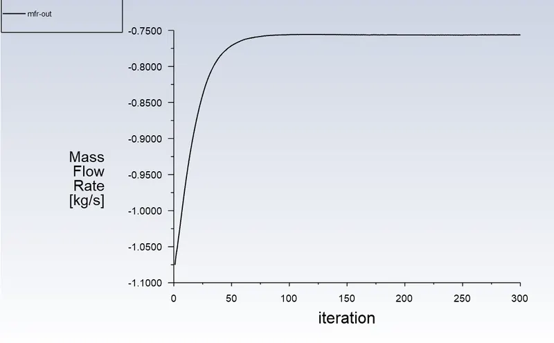
Value = 0.75627 kg/s
Pressure at a plane before gate valve
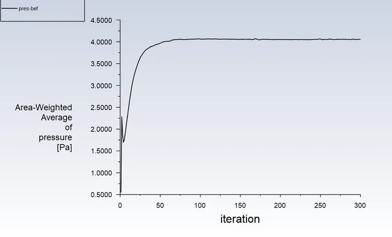
Value = 4.055 Pa
Pressure at a plane after gate valve
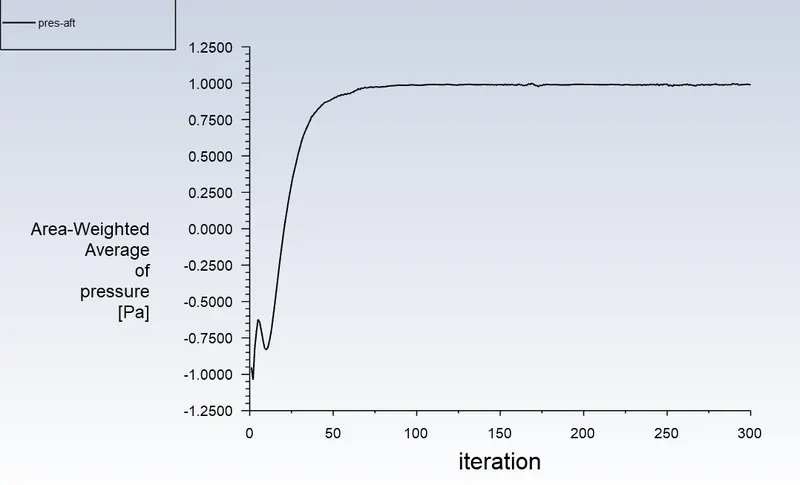
Value = 0.99128 Pa
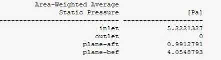

These values are same as the displayed parameter output


CFD post
Static Pressure plot
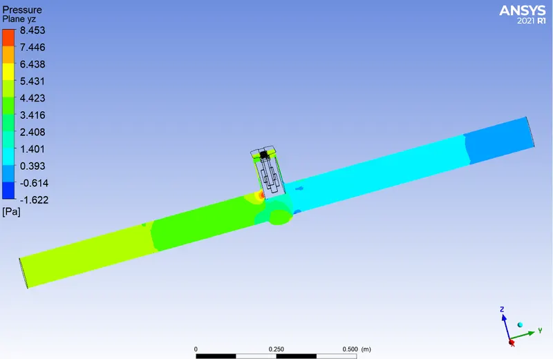
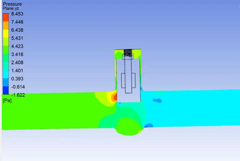
Total Pressure plot
a) Contour of inlet & outlet
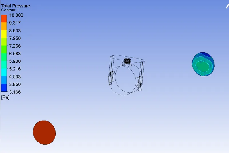
b) Pressure along the length of the pipe
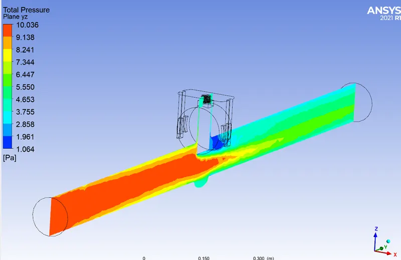
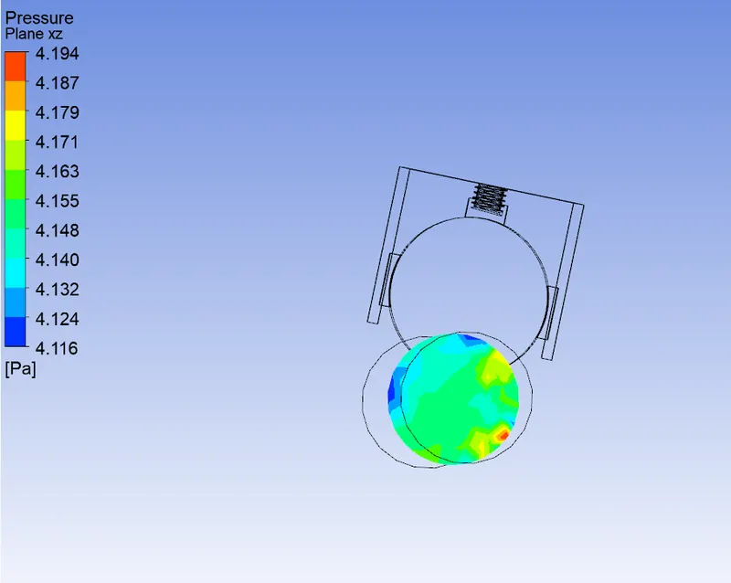
Velocity plot
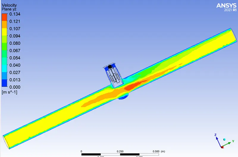
Video file: FFF80.wmv
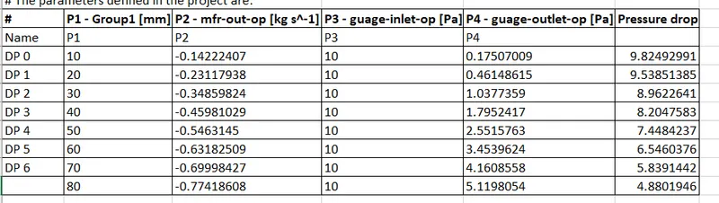
The overall pressure drop as per lift parameter is shown below
Flow Coefficient Definition
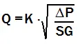
When flow goes through a valve or any other restricting device it loses some energy. The flow coefficient is a designing factor which relates head drop (Δh) or pressure drop (ΔP) across the valve with the flow rate (Q).
 (liquids)
Q: Flow rate
ΔP: Pressure Drop
Sg: Specific gravity (1 for water)
K: Flow coefficient Kv or Cv
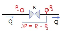
Each valve has its own flow coefficient. This depends on how the valve has been designed to let the flow going through the valve. Therefore, the main differences between different flow coefficients come from the type of valve, and of course the opening position of the valve.
Flow coefficient is important in order to select the best valve for a specific application. If the valve is going to be most of the time opened, probably there should be selected a valve with low head loss in order to save energy. Or if it is needed a control valve, the range of coefficients for the different opening positions of the valve should fit the requirements of the application.
At same flow rate, higher flow coefficient means lower drop pressure across the valve.
Depending of manufacturer, type of valve, application the flow coefficient can be expressed in several ways. The coefficient can be non-dimensional or with units if parameters such as diameter or density are considered inside the coefficient or just in the equation.
Most of valve industry have standardized the flow coefficient (K). It is referenced for water at a specific temperature, and flow rate and drop pressure units. Same model valve has different coefficient for each diameter.
Kv is the flow coefficient in metric units. It is defined as the flow rate in cubic meters per hour [m3/h] of water at a temperature of 16* celsius with a pressure drop across the valve of 1 bar.
Cv is the flow coefficient in imperial units. It is defined as the flow rate in US Gallons per minute [gpm] of water at a temperature of 60* fahrenheit with a pressure drop across the valve of 1 psi.
Cv = 1.156 x Kv
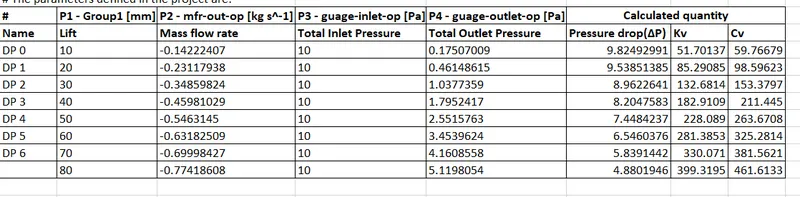
- Discuss the results of the mass flow rate and flow coefficient.
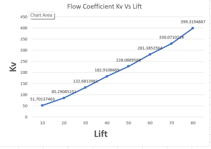
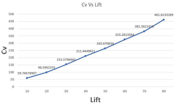
As the mass flow rate increases by increasing the value of lift of gate disc, the value of flow coefficient increases.
Graph of Cv and Kv Vs Lift