Week 2 Challenge : Surface meshing on a Pressure valve
AIM
Check for the geometrical errors and perform Topology cleanup and mesh the model for 3 different target length using 'Tria' element type. The 3 target length are 1 mm, 3 mm and 5 mm
PROCEDURE
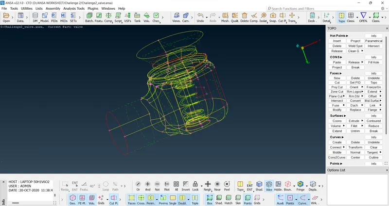
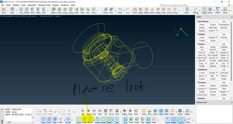
The model is downloaded and changed to wire frame mode to view the errors as shown below. it is done by disabling shadow button or press Ctrl+Shift
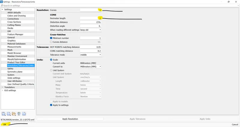
Then the resolution settings changed to 1 and press OK as highlighted in image below
Then after performing the geometrical cleanup, the figure looks like this. Please see both shadow and wire frame mode below. Wire frame mode is shown after disabling perim and cross hatch
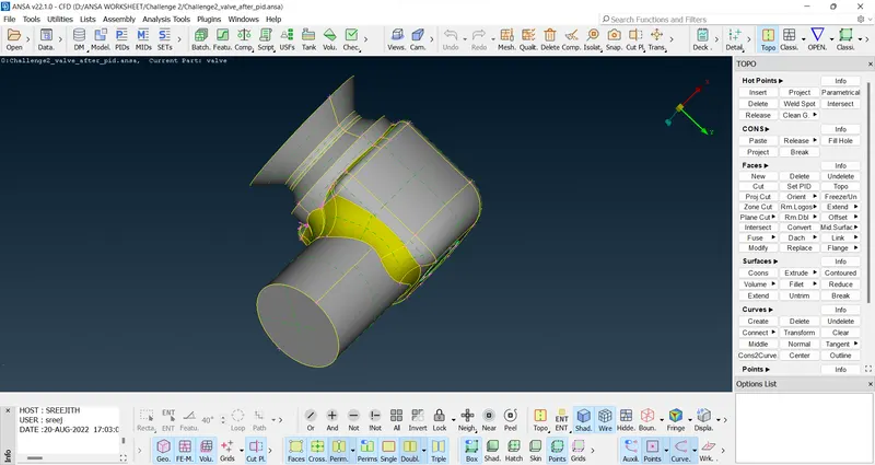
After that PID is assigned to each entities of the model
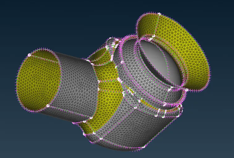
Please see the PID name of each component below
Inlet
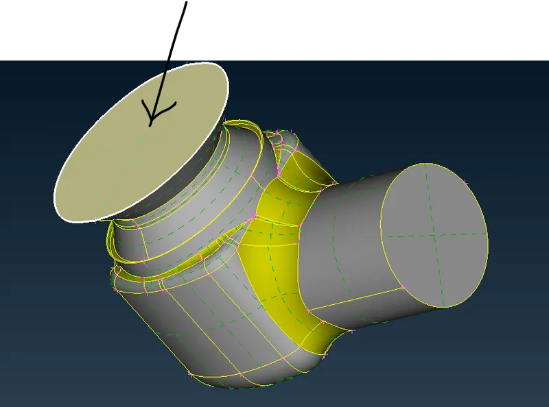
Outlet
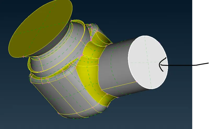
Body
The outer covering is the body
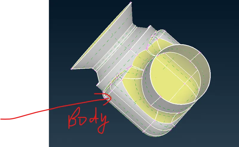
Now, after disabling the PID of outer side, we can move to inner side. This can be done using Not option or disabling the PID from PID box
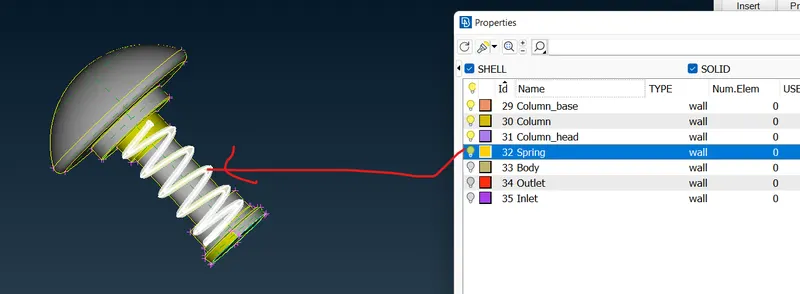
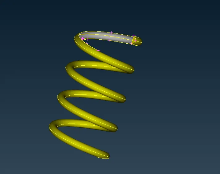
Spring
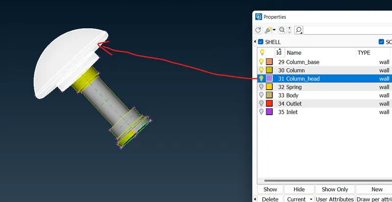
Column_head
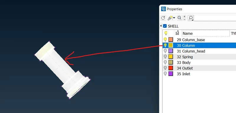
Column
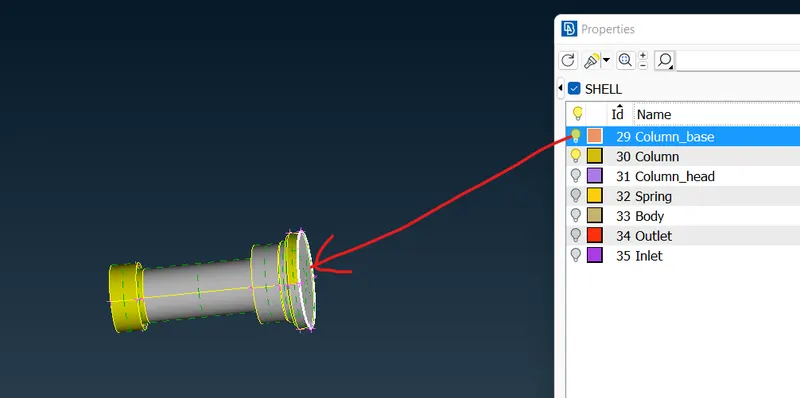
Column_base
The PID box is shown below. We can select whatever PID we want. If we select a particular PID, it gets selected
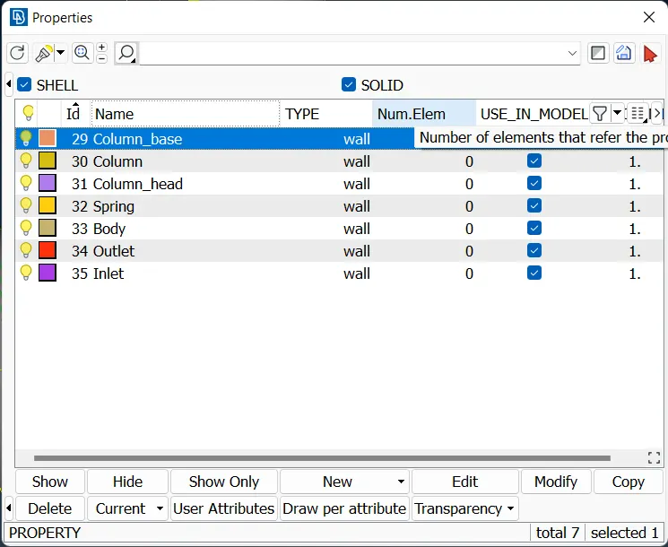
We select PID box from the menu bar as shown below

If we want some particular PID only, we can select that PIDs by disabling other PIDs
In the figure below, only 4 PIDs selected. So, we can see only 4 PIDs as shown below
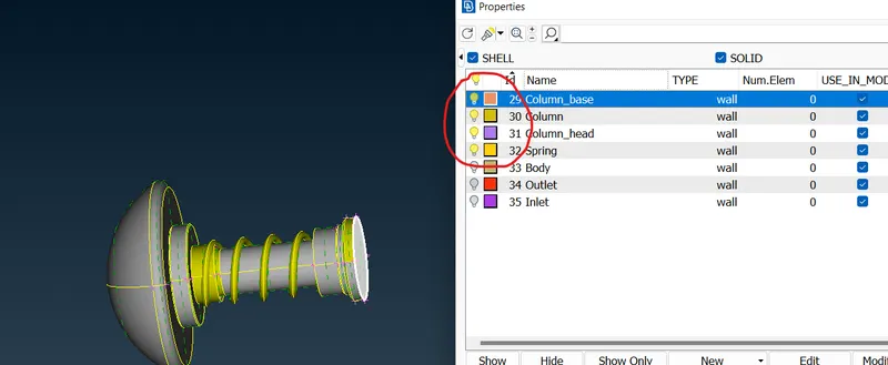
Now, we can come back to original geometry. So, click on All button to retrieve all PIDs

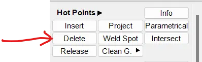
Now, the unnecessary hot points can be deleted using delete option from Hot point
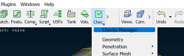
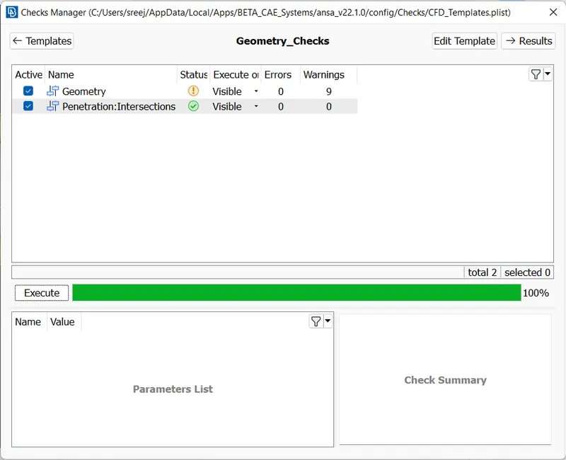
Now, we can use check manager from menu bar to check errors and perform geometry checks.
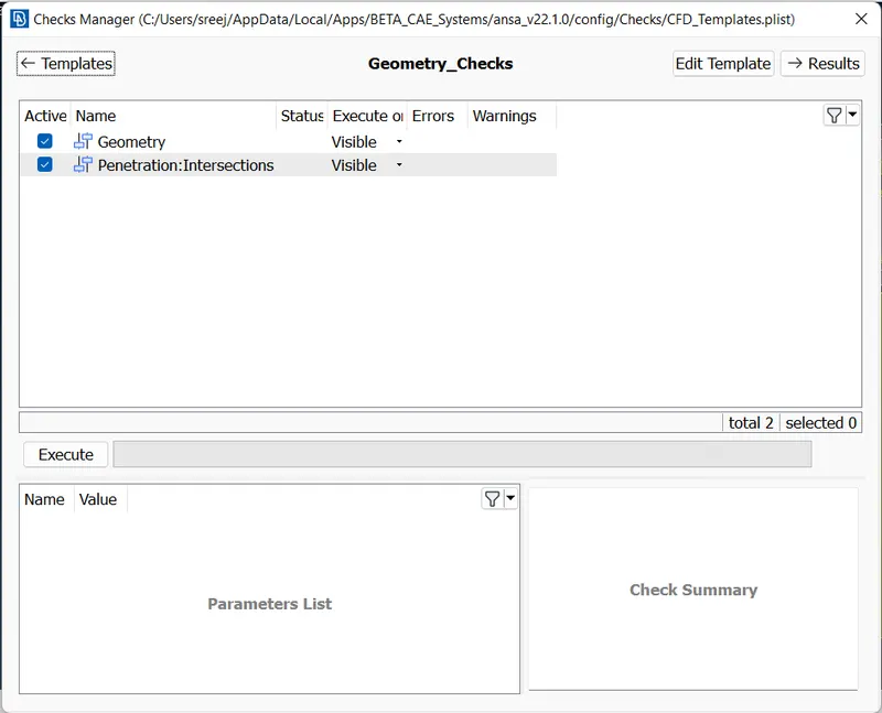
Click on execute now
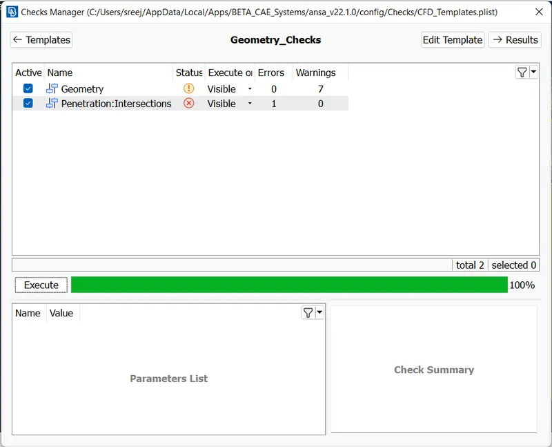
We can see 1 penetration errors and 7 warnings in geometry. We can or cannot remove warnings as per our requirements.
Now, we go to clear intersection errors
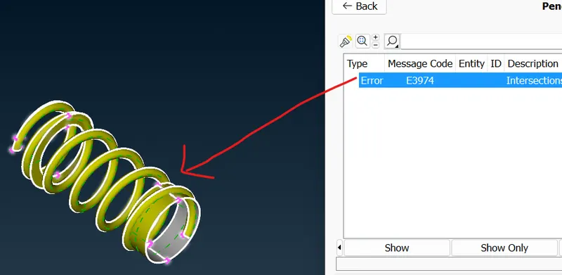
So, we isolate the springs and columns
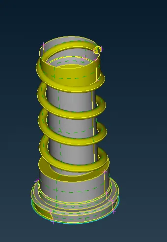
Click on Intersect from Faces
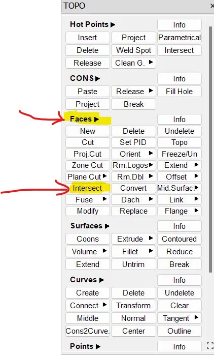
Now, we see the box like this
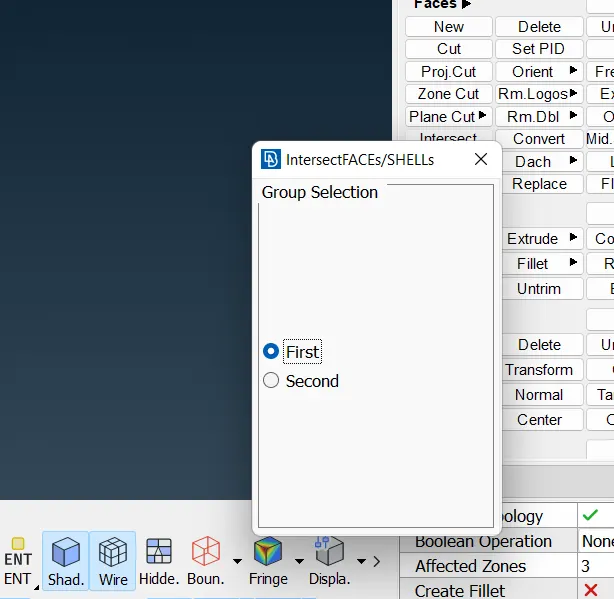
We want to select 2 intersecting PIDs. Select Column as First and Spring as Second and remove the unnecessary surfaces.
After removing it, we are going to Check manager again.
Now the penetration errors are completely cleared
Now, look at warnings from geometry
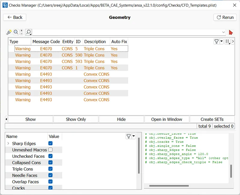
As these warnings are unavoidable, we are ignoring it.
Now, we are going for meshing.
Select classic mesh
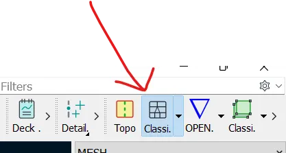
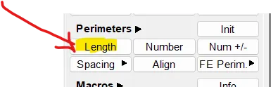
Select Length from Perimeters
Now a pop up window appear like this
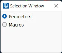
Set the required length in the perimeters and macros section. Now, I m using 3.
After that, go to select Mesh and Quality Criteria.
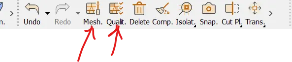
For 3 mm mesh, set the parameters as shown below
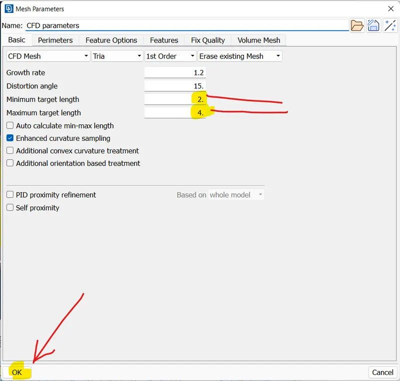
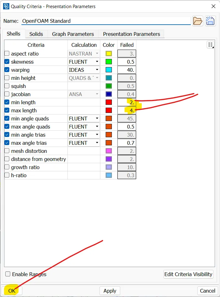
After that, select CFD mesh from mesh generation and apply mesh seperately to each PIDs
Inlet
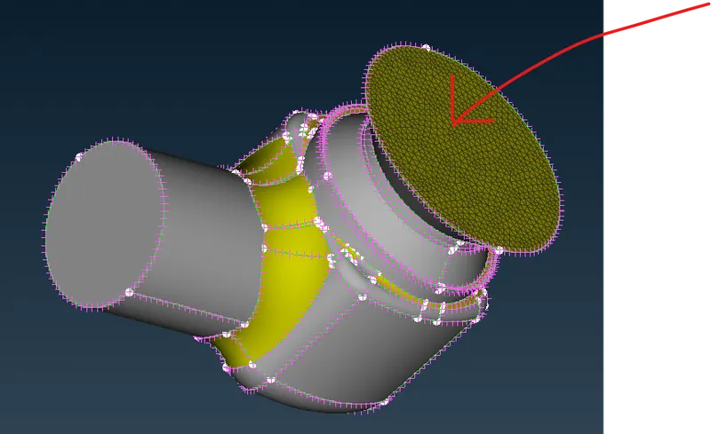
Outlet
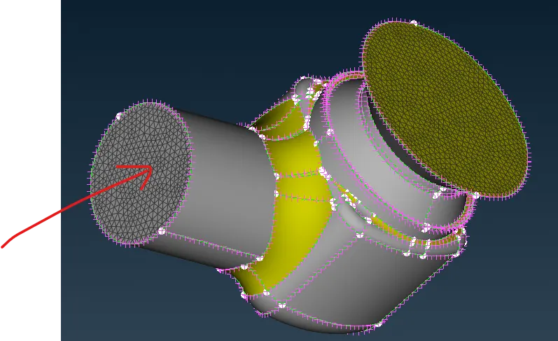
Body
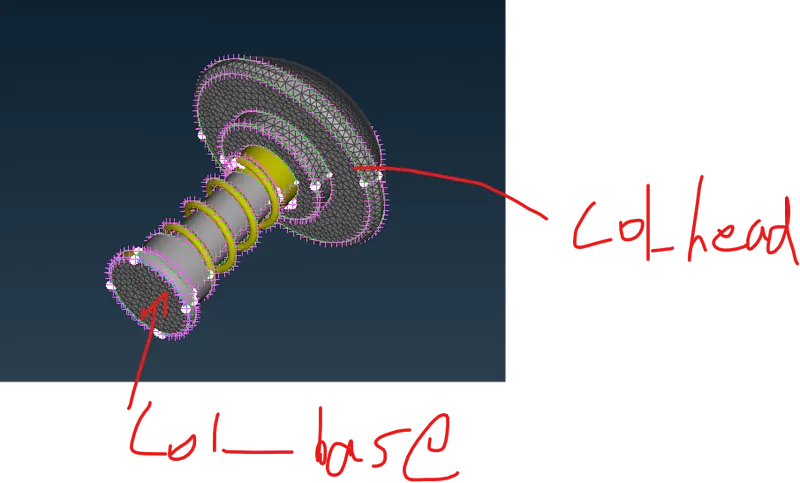
Column_head and Column_base
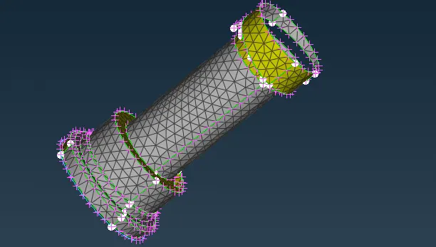
Column
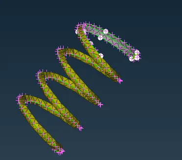
Spring
After meshing finished, Click on All to bring all the surface back to screen.
After that, execute geometry checks again and check for unmeshed macros.
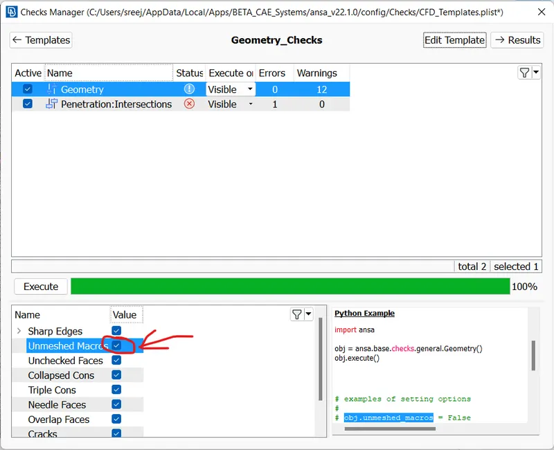
If, we didn't get error from unmeshed macros, we meshed all macros.
Try meshing target length for 1 mm and 5 mm
LEARNING OUTCOMES
1. How to clear geometrical errors using the available functions such as cons,fill hole
2. How to assign PIDs for each region
3. How to remove intersection errors using intersect option under face
4. How to do CFD meshing
ATTACHMENTS
The 1 mm mesh file is attached as Challenge2_valvefinal_1mm_meshed1.ansa
The 3 mm mesh file is attached as Challenge2_valvefinal_3mm_meshed3.ansa
The 5 mm mesh file is attached as Challenge2_valvefinal_5mm_meshed5.ansa
OBSERVATIONS
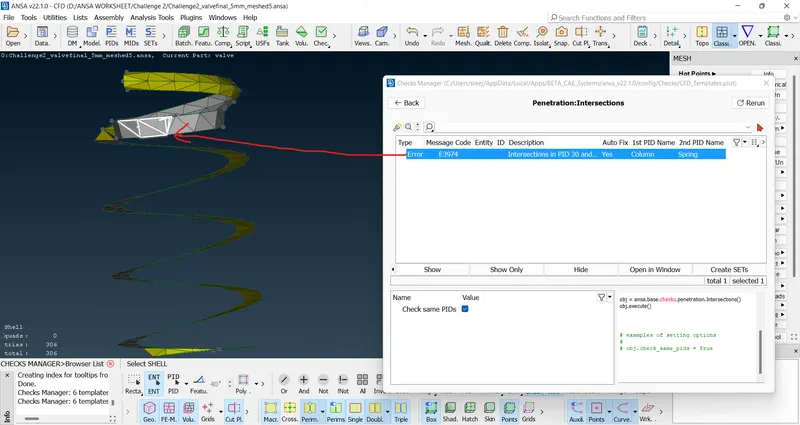
The mesh target length of 1 mm gives the good result because there is no intersection error after meshing with 1 mm. But intersection error is there if we mesh with 3 mm or 5 mm as shown below.
Figure below shows spring with mesh length 3 mm
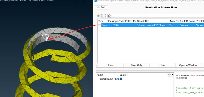
Figure below shows spring with mesh length 5 mm
There is no penetration error if we mesh with 1 mm
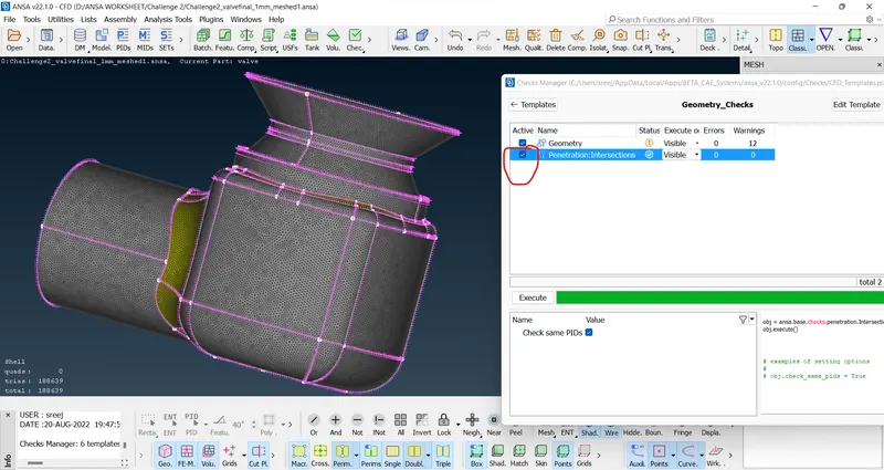
Figure below shows spring with mesh length 1 mm
CONCLUSION
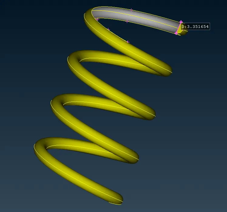
If we go to reduce the mesh length, the more finer is the geometry. The distortion of geometry is very less in case of smaller mesh length. This can be easily understood if we take the case of spring which is mentioned just above. If we check the coil thickness, we will get it as 3.35 mm. So, if we mesh with 3 mm or 5 mm, the meshing will distort the original geometry. So, 1 mm mesh will give good result.