Week 3 - External flow simulation over an Ahmed body.
Given data
Flow velocity of air = 25 m/sec.
The geometry of the Ahmed body along with all dimensions is as given below in the figure.
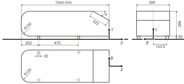
For our model slant angle is 20*.
Theory
The Ahmed body is a generic car body (a simplified vehicle model). The air flow around the Ahmed body captures the essential flow features around an automobile like wake forces, drag forces etc. and was first defined and characterized in 1984 by Ahmed et. al. the Ahmed body is designed to have smooth-edged front end with a flat roof and a flat bottom section and an angle back slant which basically acts as the rear window of a car end ending with a vertical base. The back slant angle which is commonly designed as $ is very critical to the flow patterns which are fashioned at the near wake reason and subsequently has an impact on the aerodynamic forces which act on the body. Car companies makes numerous attempts to develop modified designs to effectively reduce the aerodynamic drag force which occurs at the rear end without putting any constraints in the stability, comfort and safety of the passenger. The aerodynamic drag of road automobiles is firmly connected to the vehicles with downstream flow. The separation zone size and the drag force directly rest mainly on the position of flow separation over the Ahmed body. Subsequently, comprehensive facts regarding the wake flow characteristics and its connection with the geometry of body is essential for a successful design of upcoming future cars. The application of computational fluid dynamics in in determining fluid flow pattern has been observed to be very common among researches in the present days. CFD Modelling in determining flow line of fluid around the Ahmed body has been utilized since the early `21^(st)` century. In many open literatures the CFD application in determining air flow pattern and the changes in flow motion with altering geometry of the body have been found. Certain modifications in the and body aids researches and designers to determine the effect of modification on the resultant drag and lift force which can be calculated using CFD modelling. Purpose of automotive is reduction of drag, decreasing noise emission, increasing fuel economy and eliminating unnecessary lift force and other origin of aerodynamic unsteadiness which rises at high speed. The conventional and reference model has been considered as the standard model in this research work for carrying out numerical simulations for researching on the aerodynamic parameters the Ahmed body has a like featured like a general car and is broadly utilized for authentication of new quotes in the automobile industry. This simple geometric model has a length of 1.044 m height of 0.288m and a width of 0.389 m. It consists of cylindrical legs of 0.5 m radius attached to the bottom most part of the body. The real most surface has an inclination of 25 degree. Ahmedabad characterizes the simplified geometry of a ground vehicle as a bluff body type. Its geometry is adequate enough for precise flow simulation and returns few vital practical features relevant to cars. This model aids engineers and designers to generate turbulent flow field surrounding the simple car model by the use of K-epsilon model. In spite of neglecting quite a few numbers of features of a real car like rough underside rotating wheels, surface projection etc. Ahmed body generates the crucial feature of flow pattern around a car for instance flow impinge-mentation and the displacement around the nose, relative uniform flow of air around the middle portion and flow separation along with the wake generation at the rear. Since the Ahmed body is easy to model, it can be a place is utilized for researching various properties like turbulence, drag coefficient, wake reason, lift forces, velocity magnitude at various regions of the car. Magnitude of pressure around the car which helps in in determining what will be resistance, fuel efficiency etc. Of the car thereby providing designers a clear Idea on which reason needs to be optimized for better effectiveness. The main objective of this study being stimulation of turbulent flow within the wind tunnel and around the Ahmed body to capture the flow pattern at the rear and wake region. Are local refinement of mess inside the concerned body is done with necessary body and face sizing of the parts of the body to generate well defined plots for pressure and velocity contours and its grid dependency test is the primary focus of this project.
Case setup
Geometry
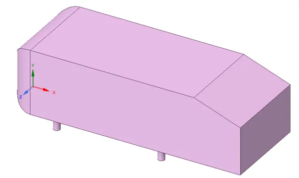
- Import Ahmed body geometry in the SpaceClaim.
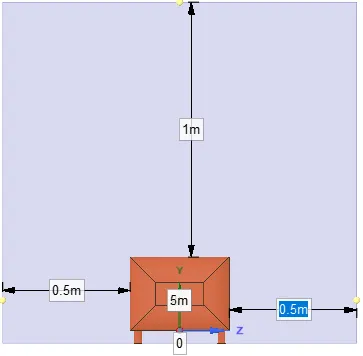
- Prepare an Enclosure for the Ahmed body
Side view

Front view
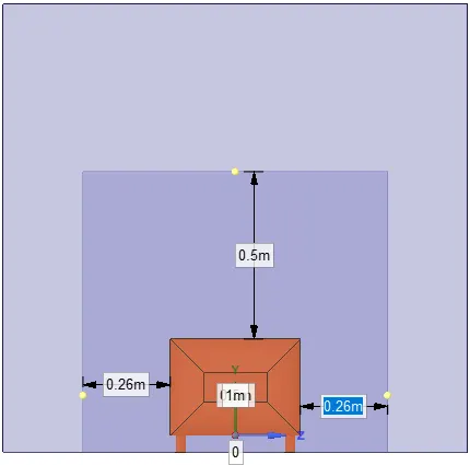
- Add another Enclosure of smaller dimensions.
Side view
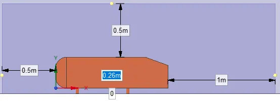
Front view
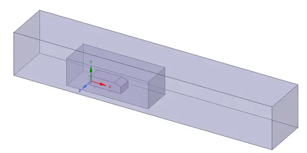
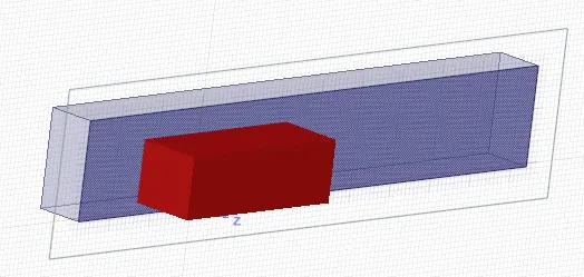
Final geometry after adding Enclosures is shown below:
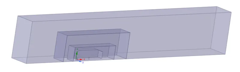
- Add an XY plane by clicking on origin. Then use the split body so that we cut the body into 2 equal half to reduce the cell count
- View in section mode for the interference.
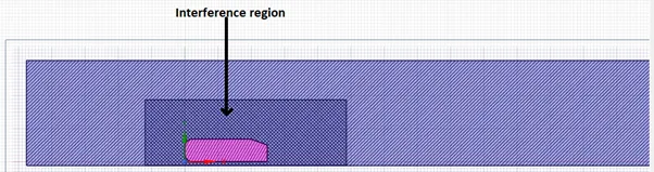
- In prepare section click on interference it will show interference region.
- Press on green tick and I will resolve the interference problem.
Resolved interference
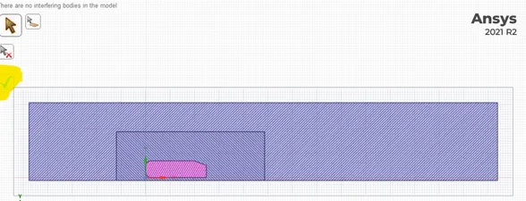
- Suppress the Ahmed body for physics.
Click on share topology for FFF.
- Close SpaceClaim
Meshing
- Open meshing interface and do the named selections as shown below
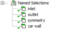
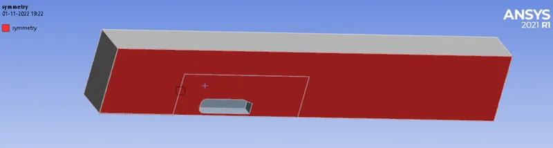
inlet,outlet and car walls that are same as shown in the course video. I made changes for symmetry.
Meshing is done as shown below
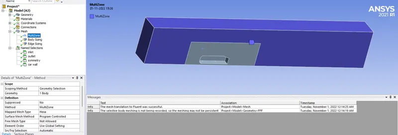
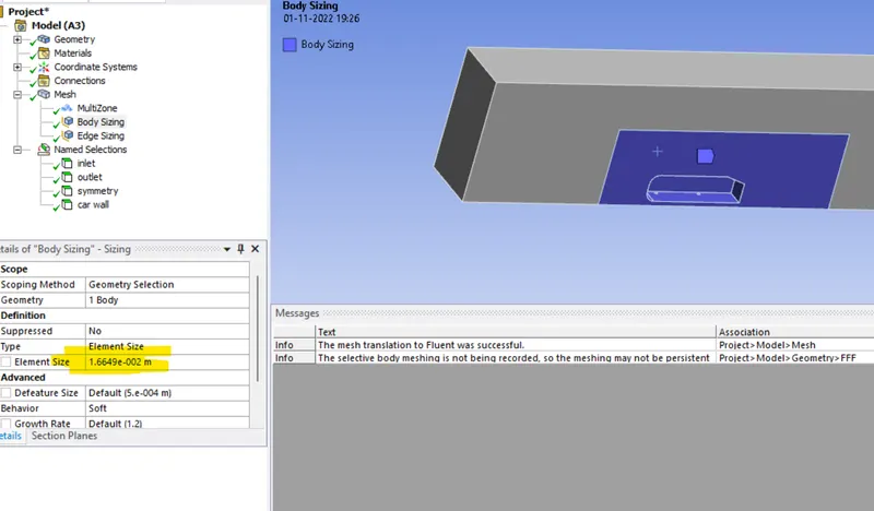

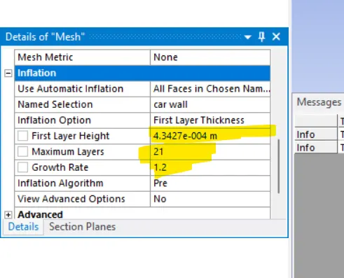
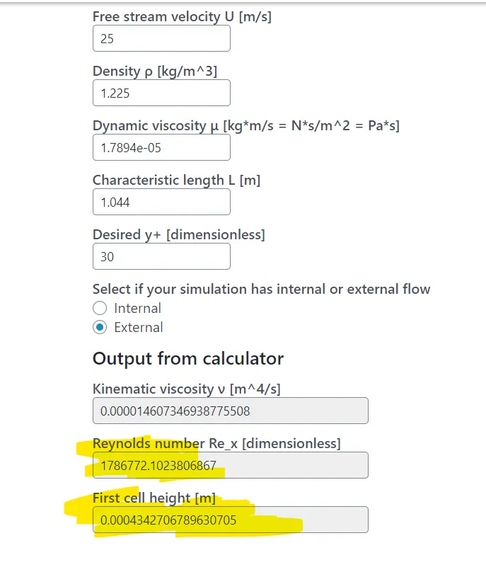
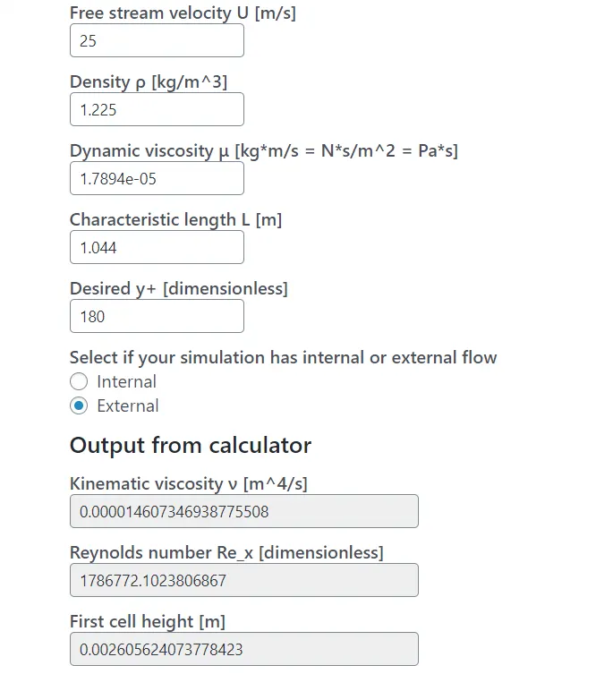
The inflation layer that I added is based on y+ value. I choose y+ = 30. The calculation will be shown later
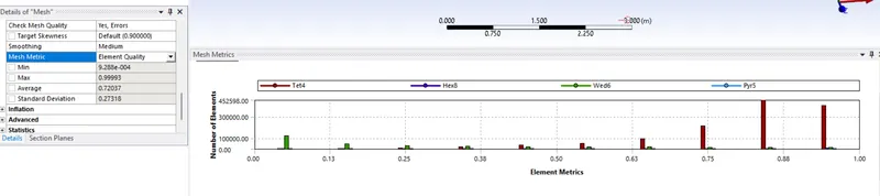
The mesh quality is shown below
The y+ value calculated is shown below.
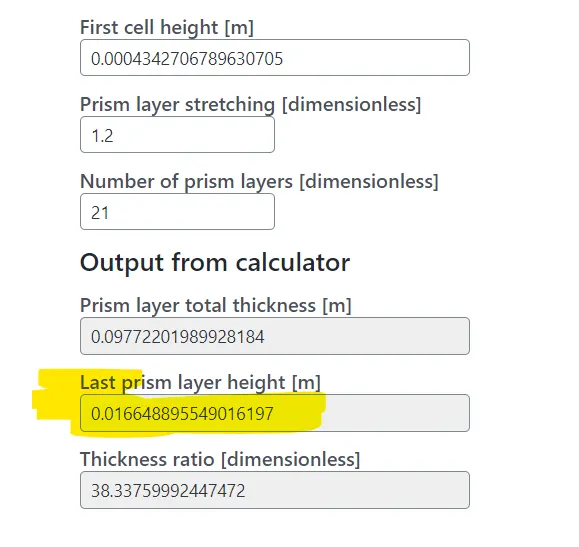
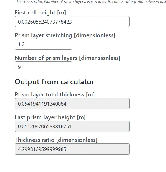
The first cell height is added to inflation layer height
The last prism layer height is such that it is equal to mesh size
Setup
- open fluent setup and perform mesh check to ensure mesh generated is free from errors.
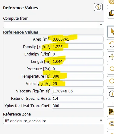
Set Reference values
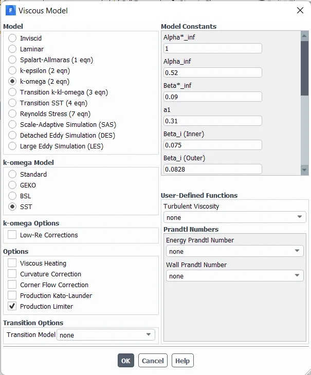
- change viscous model to realizable K-Omega SST model.
- Add material type as fluid and material air.
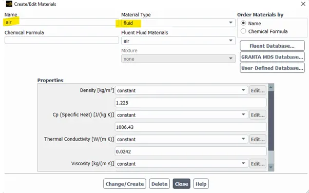
- Change boundary conditions:
- Car wall = wall
- Outlet = pressure outlet
- Symmetry = symmetry
- Inlet = velocity
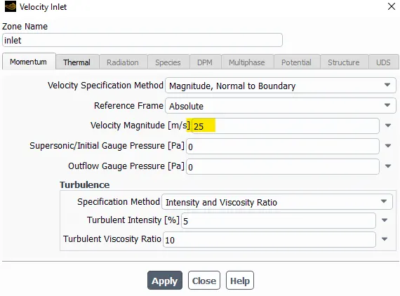
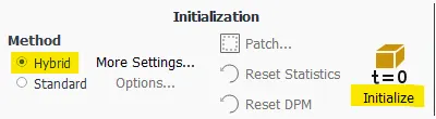
- Now perform hybrid initialization.
- Create a velocity contour at symmetry plane
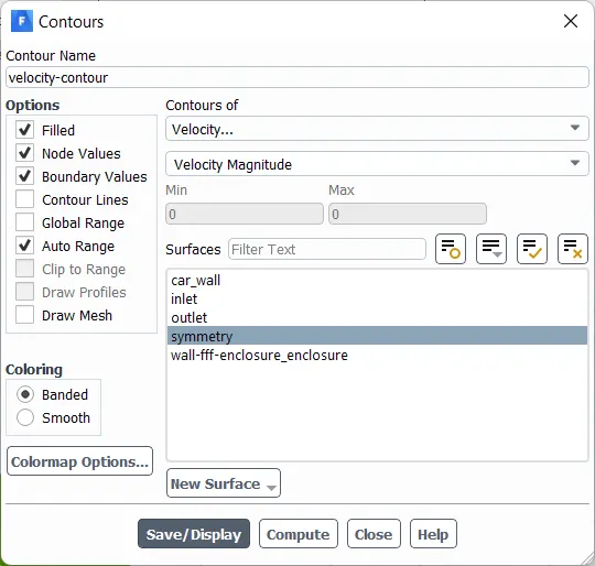
- Similarly create a pressure contour
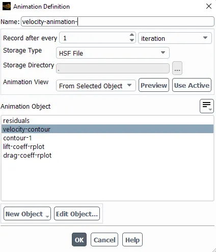
- Create animation for velocity contour.
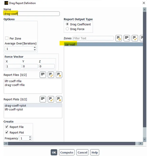
- Create a definition for drag coefficient.
- Similarly create definition for lift coefficient.
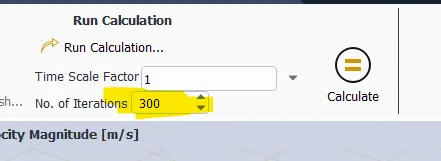
- Run calculation, iteration is 300 nos
Now the mesh independent study takes place
----------------------------------------------------------------------------------------------------------------------------
1) Case – 1
For bigger Enclosure
y+ = 30;
Mesh element size = 0.1 mm
Maximum size = 0.1 mm
Inflation (car wall) no. of layers = 21
Growth rate = 1.2
Inflation option = first layer thickness
First layer thickness = 0.0004342706789630705 m
For smaller Enclosure
Body sizing
Element size = 0.016648895549016197 m
Face sizing bottom leg
Element size = 0.001 m
No. of nodes = 374546
No. of elements = 1546355
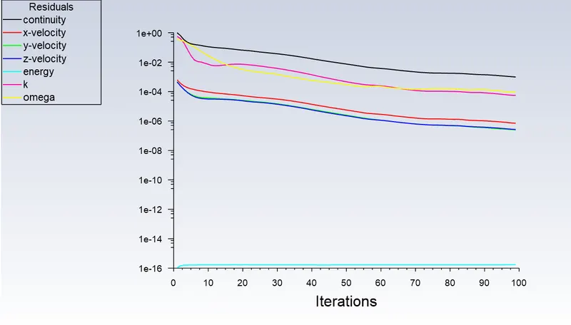
Residuals
Coefficient of drag
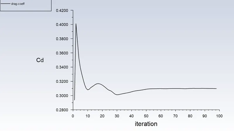
Value = 0.30963158;
Coefficient of lift
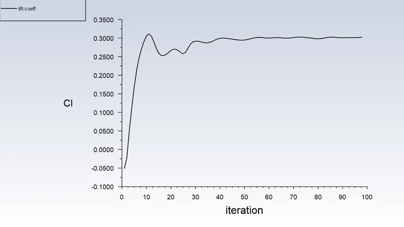
Value = 0.30286695;
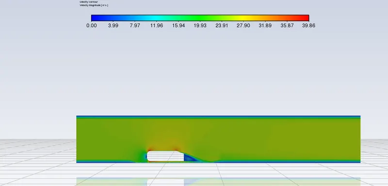
Velocity contour
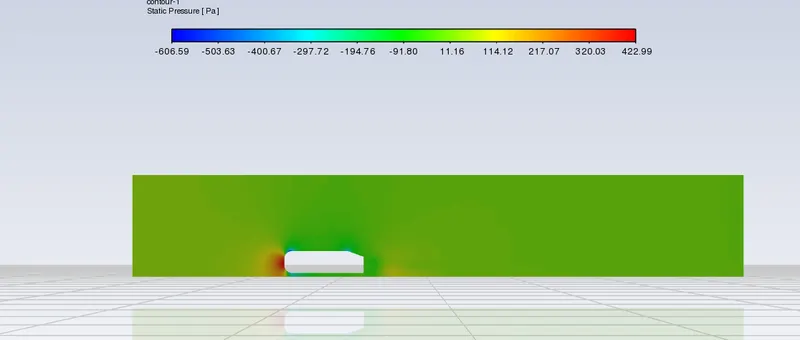
Pressure contour
a)Static pressure
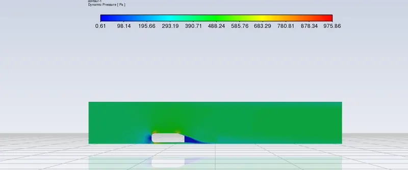
b)Dynamic pressure
c)Total Pressure
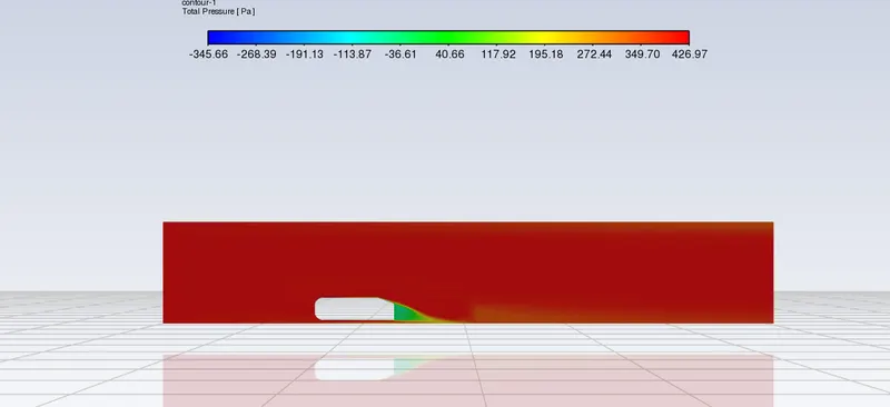
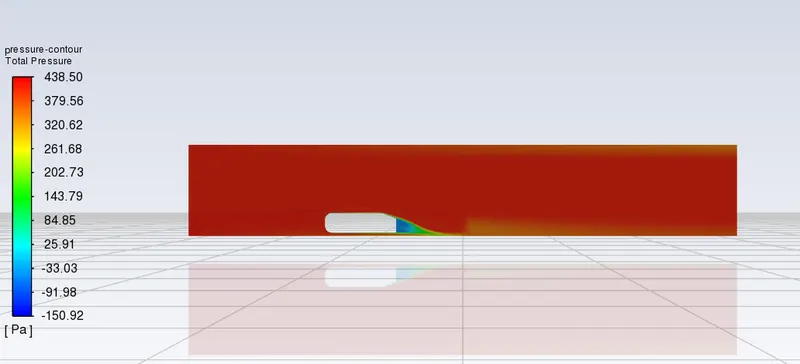
Total Pressure at any pont is defined below
Total Pressure = Static Pressure + Dynamic Pressure
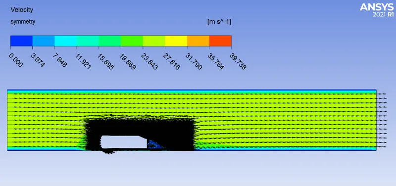
Vector plot
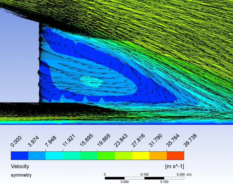
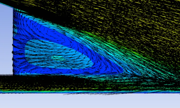
Zoomed view showing the wake region
The velocity animation video from Fluent is shown below
2) Case – 2
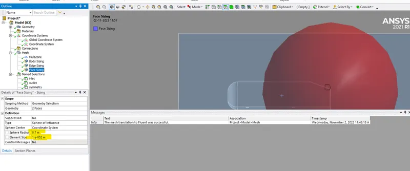
In order to capture the wake region better, I m using sphere of influence. y+ = 100
For bigger Enclosure
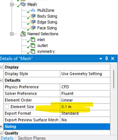
Mesh element size = 0.1 m
Maximum size = 0.1 m
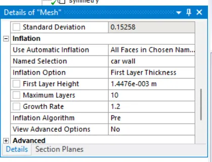
Inflation (car wall) no. of layers = 10
Growth rate = 1.2
Inflation option = first layer thickness
First layer thickness = 0.0014475689298769016 m
For smaller Enclosure
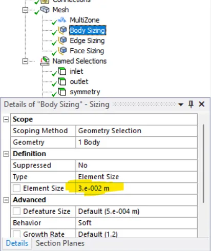
Body sizing
Element size = 0.03 m
For 2 faces at rear side, sphere of influence is used
Edge sizing bottom leg
Element size = 0.001 m
No. of nodes = 426991
No. of elements = 2113786
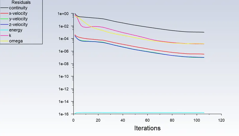
Residuals
Coefficient of drag
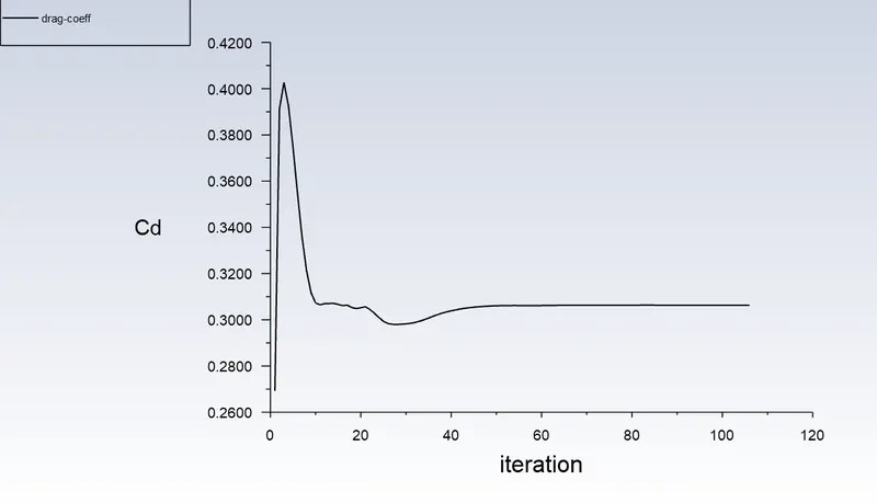
Value = 0.30630111;
Coefficient of lift
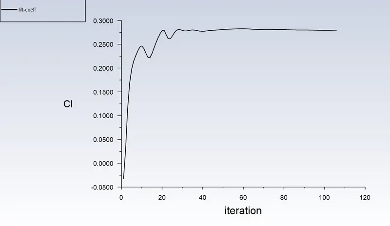
Value = 0.27962795;
Velocity contour
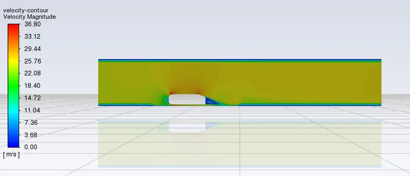
Pressure contour
a)Static pressure
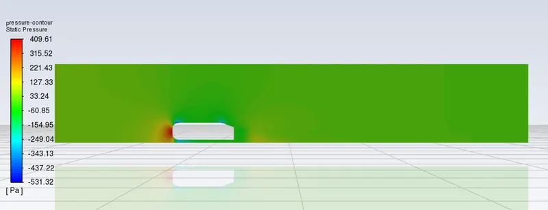
b)Dynamic pressure
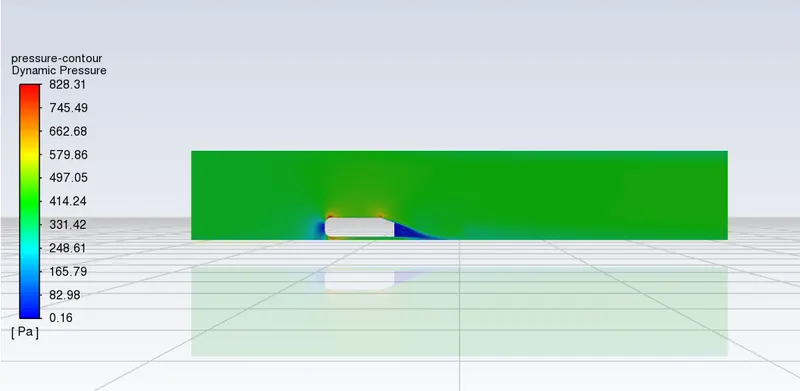
c)Total pressure
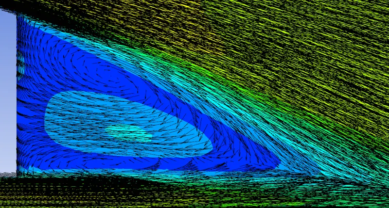
Vector plot
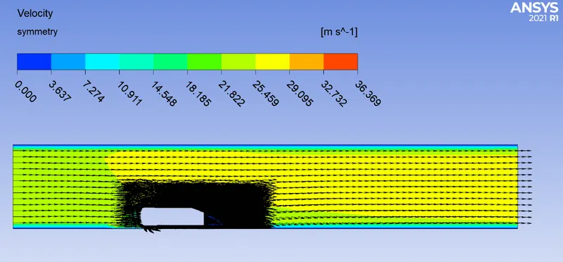
Wake region
3) Case – 3
Here my aim is to find the more accurate value of drag coefficient only. So the mesh near to all area needs to be more refined
a)y+ = 100
The sphere of influence is in the region shown below
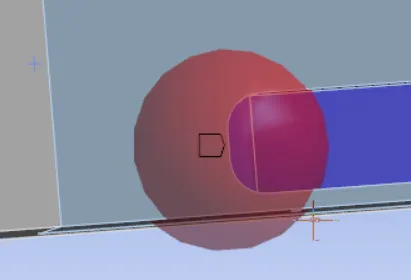
By doing this, I m focussing more on pressure drag, the frictional drag values are not properly captured here
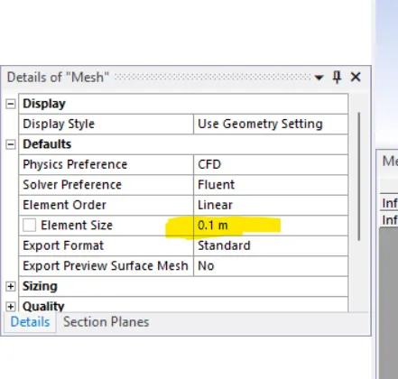
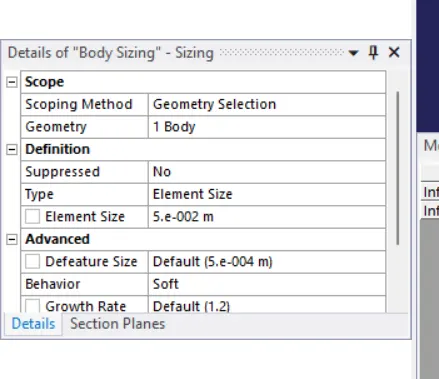
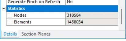
The mesh parameters are shown below
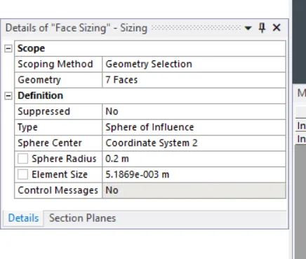
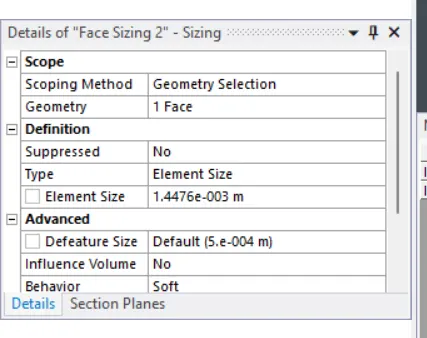
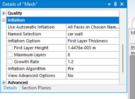
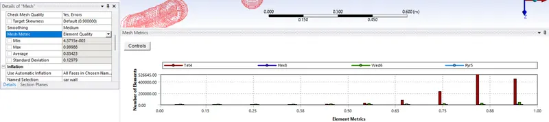
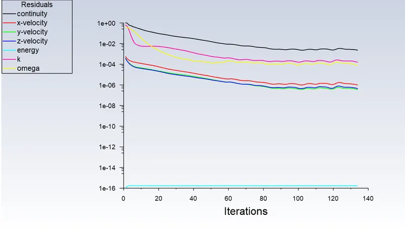
Residuals
Coefficient of drag
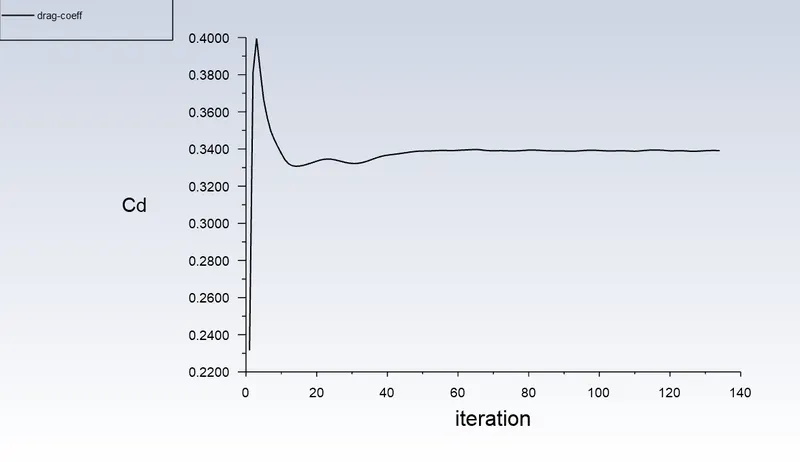
Value = 0.33915673;
Coefficient of lift
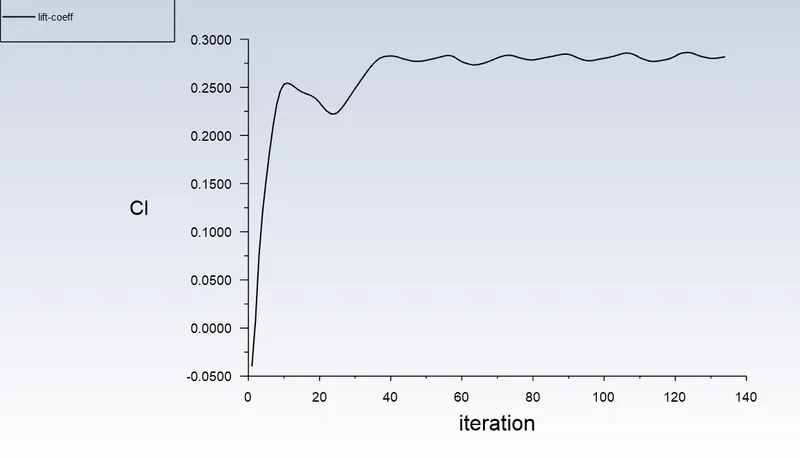
Value = 0.28171271;(The lift values are oscilating)
Velocity vector
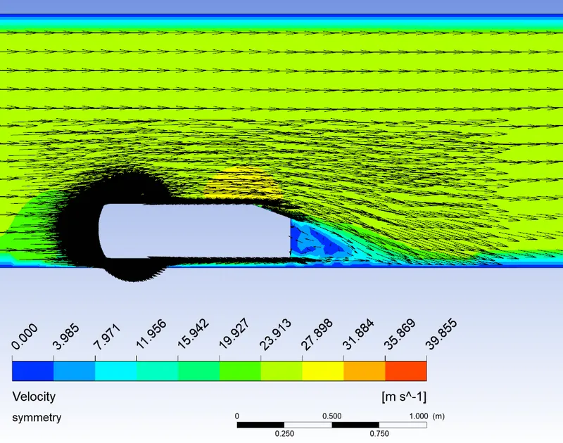
The velocity features are not captured properly because my area of interest is drag. Here the frictional drag is not captured properly
Case
b) y+ = 30
Cell count is higher.
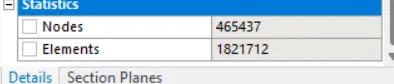
Mesh quality is not good

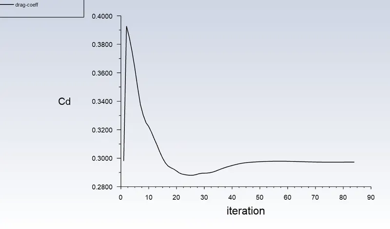
Drag coefficient = 0.29727931
Lift coefficient = 0.29918764
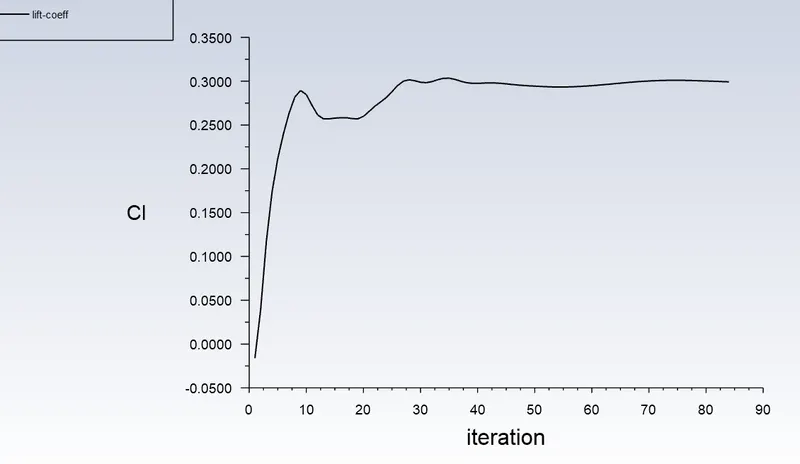
As the mesh quality is not good, there may be chance of error in final result
-----------------------------------------------------------------------------------------------------------------------------------------------------------------------------------------------------------
c) y+=180
OPTIMISED MODEL FOR INDUSTRY
The values put appropriately
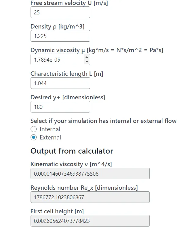
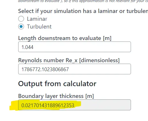
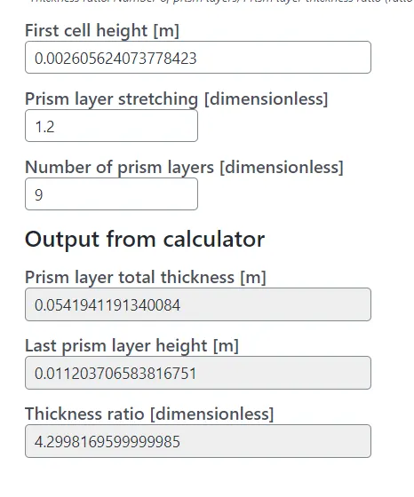
The mesh elements are reduced the mesh is shown below
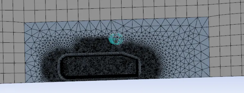
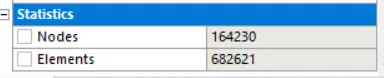
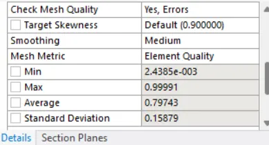
Here the mesh quality is good, because standard deviation is less

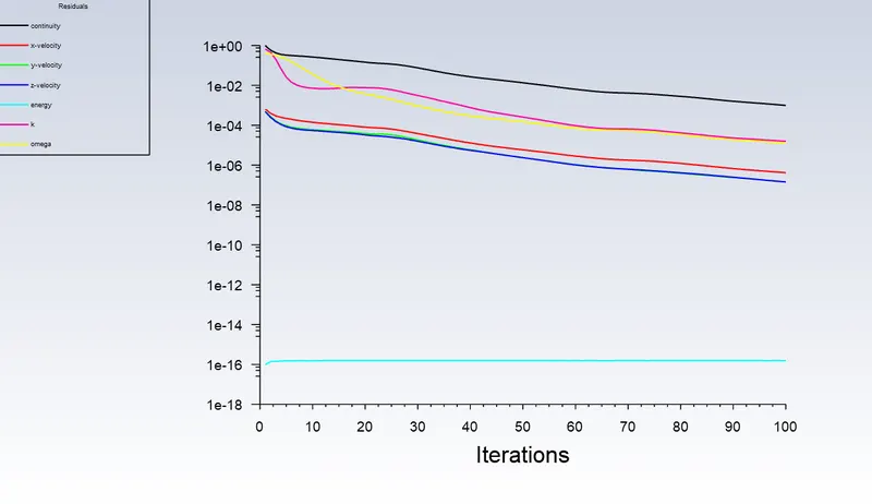
Residuals
Coefficient of drag
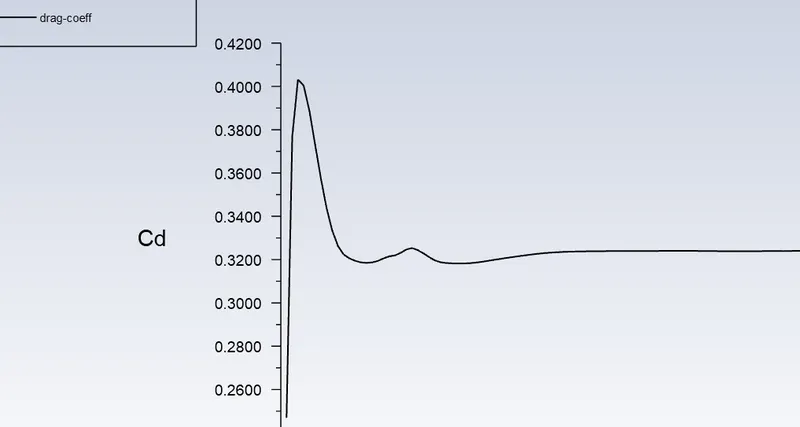
Value = 0.32405637;
Coefficient of lift
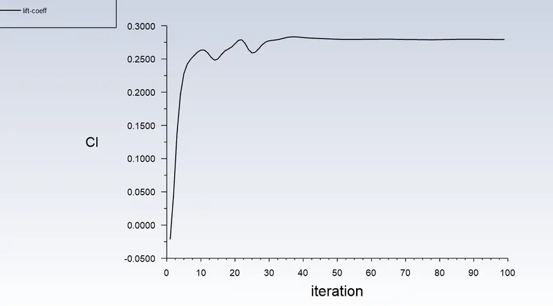
Value = 0.27912245;
Velocity vector
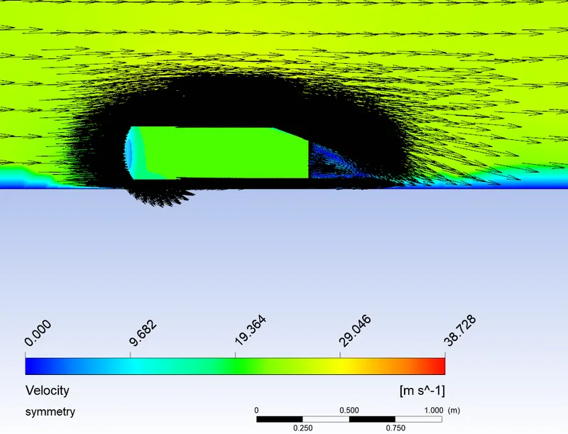
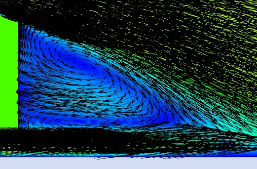
OBSERVATIONS
Cd=0.32405637;
Cl=0.27912245;
INFERENCE for this model
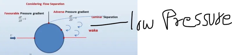
This case is the optimised model suitable for industry to reduce computational cost and predict accurate values of coefficient of drag and lift. The computational cost can be further reduced by adding some small changes in this model, it is easy for anyone to make small changes to my model. The value of coefficient of drag is calculated by considering pressure drag, viscous drag, reduction of drag due to negative pressure, negative pressure at slant of the Ahmed body at wake region by making use of K-Omega SST model. The characteristics length is taken based on the reference from the journals. The values are then compared with standard journal in journal, where Cd=0.33 at slant angle=25*. but in our case, the slant angle is 20*.
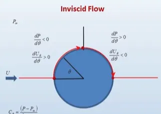
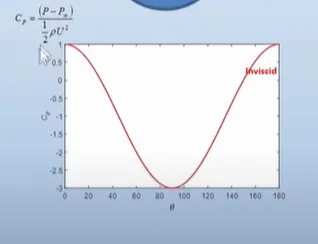
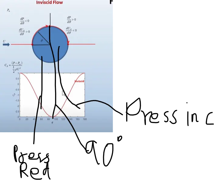
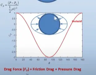
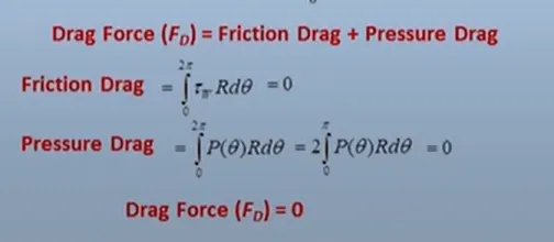
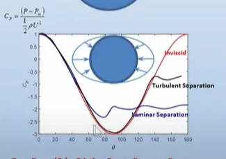
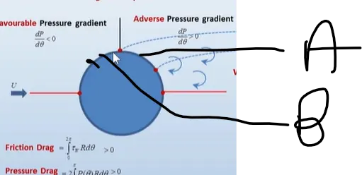
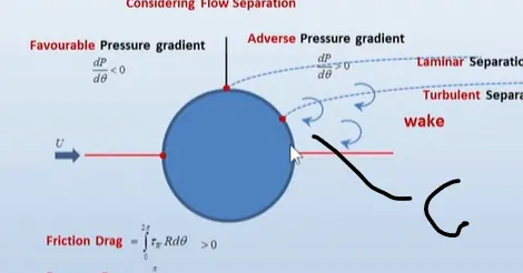
So, the slant angle of a surface behind the have high influence in determining the coefficient of drag as it plays an important role in negative pressure behind the Ahmed body. The design of backside of the vehicle is to be made in such a way to generate maximum negative pressure behind slanting region of Ahmed body. If negative pressure increases, the coefficient of drag decreases due to equipotential or inviscid flow theory.
-------------------------------------------------------------------------------------------------------------------------------------------------------------------------------------------------------------------------------
4) Case 4
OPTIMISED MODEL TO STUDY VELOCITY AND PRESSURE VARIATION IN WAKE REGION
y+ = 180;
For wake region
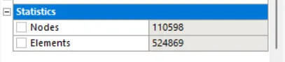
The mesh is shown below
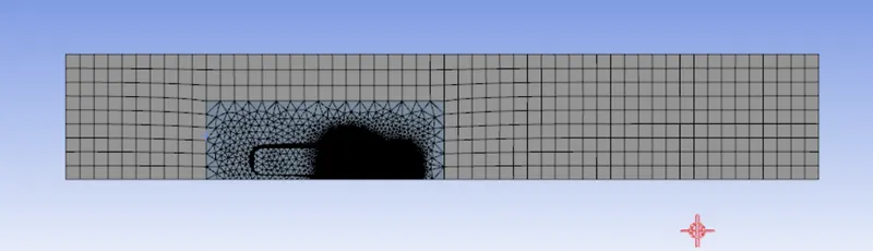
The values given as per below calculation

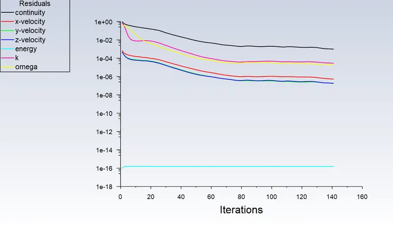
Residuals
Coefficient of drag
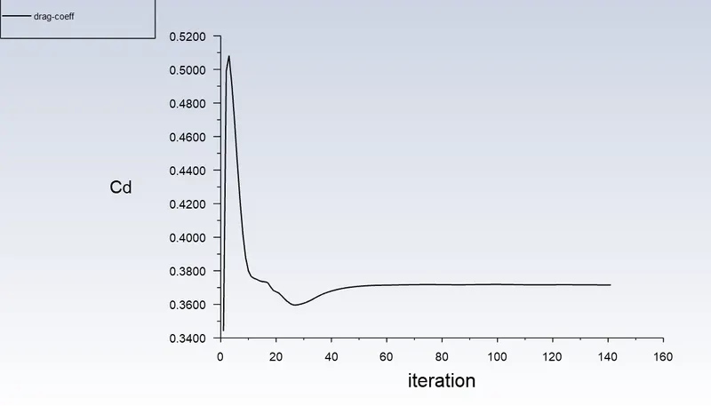
Value = 0.37160131;
Coefficient of lift
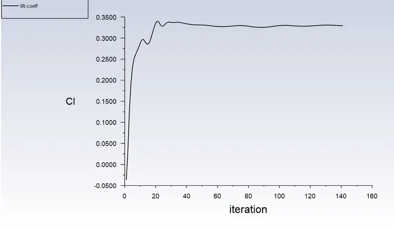
Value = 0.32925761;
Velocity vector
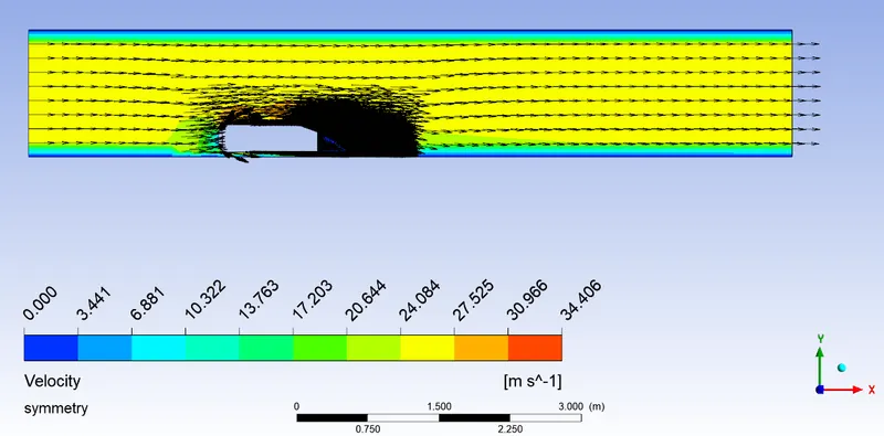
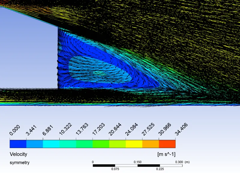
The velocity features are captured properly because my area of interest is velocity is wake region. There is change in the value of drag and lift from standard journal because the mesh is not refined in the areas of ahmed body where forces of drag and lift acting.
INFERENCE
The case 3c and case 4 models are the best suited optimised models.
a) The case 3c model, is one of the optimum model for industrial applications in order to capture the drag and lift coefficients such that the computational cost is minimum and to get the accurate values of drag and lift coefficients. The cost is minimum because of less cell count.
b) The case 4 model is suitable for the study of pressure and velocity variation in wake region. Here also the computational cost is minimum due to less cell count and it is the optimum model for study of wake region. After that apply the case 4 model to case 3 model so that computational cost can be minimised. We can do both the models in parallel for industrial application and then apply case 4 to case 3c model .
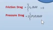
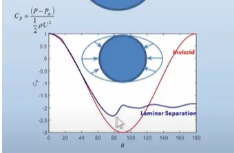
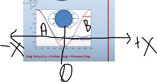
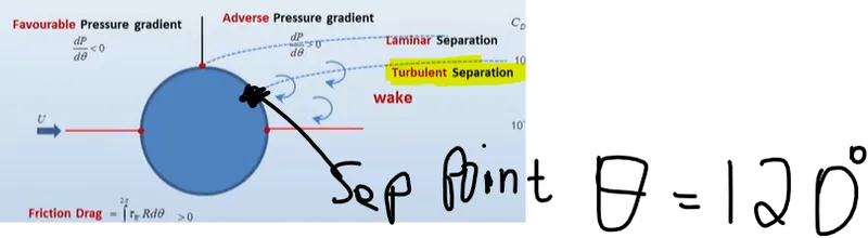
REASON FOR NEGATIVE PRESSURE in wake region
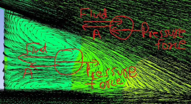
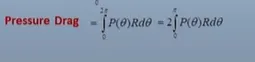
For this explanation, we have to simplify it using inviscid fluid and then apply to viscous fluid.
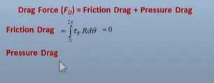
Inviscid flow is the flow of an inviscid fluid, in which the viscosity of the fluid is equal to zero.
Let us take an example of inviscid fluid fluid flow over a cylinder.
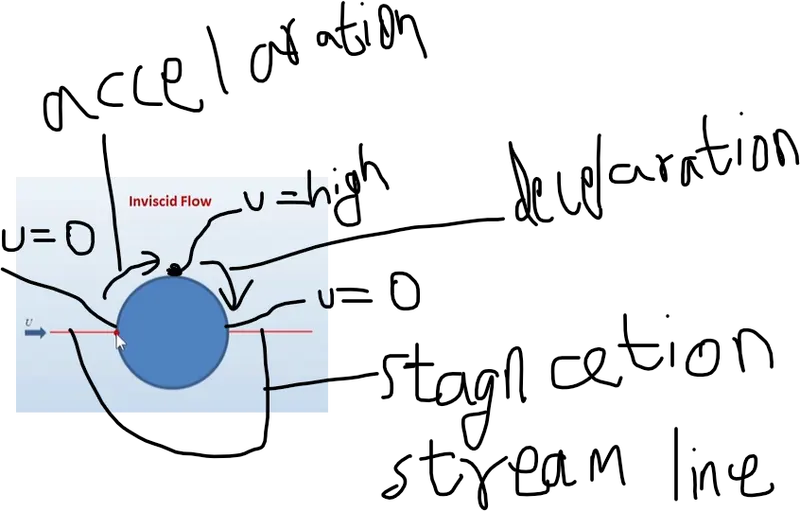
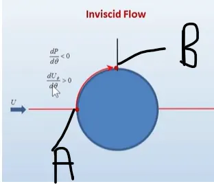
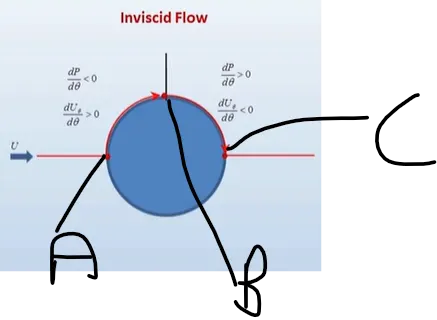



The velocity colour animation and stream line animation file is attached
LEARNING OUTCOME or GAPS
The study of inviscid flow or potential flow theory helped in doing the challenge in a better way. After studying this theory, the case 3a is modified to case 3c. The case 4 should come ahead of case 3c because after studying the effect of negative pressure, then only it is possible to implement it on industrial approach.
In this case I made case 3c without considering the negative pressure, then after studying the effect of inviscid flow or potential flow theory, I made changes to Case 3c and do it to find the better value for coefficient of drag.
The study for coefficient of lift is not done by me. The NPTEL video helped me in studying the effect of negative pressure and the journal provided by skill lync helped me to understand the effect of slant angle of the car body.