Week -2
TASK 1
OBJECTIVE
Make a Simulink model of Doorbell using solenoid block with the following details. The figure shown below
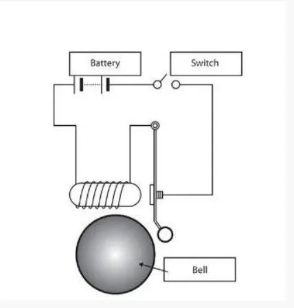
In the above arrangement, when the switch is closed the electromagnet receives electrical power from the battery and pulls the metal arm to hit the bell producing sound.
Create a situation where the switch is closed for 2 seconds and then released. Observe the physical movement of the plunger
THEORY
At first the switch is open for 2 seconds. When the switch is closed for 2 sec,it causes electromagnetic induction in solenoid which pushes the plunger towards solenoid coil. The bell is arranged in such a way that,whenever the plunger attract towards the solenoid coil,it hit the bell. When plunger hits the bell,the circuit will break between pivot point of plunger attached to the main circuit. As a result, the electromagnetic induction stops and pushes the plunger back to original position.Then the switch is open for 2 seconds.Continue this process for the input simulation time
DIAGRAM OF MAIN SIMULINK PROGRAM
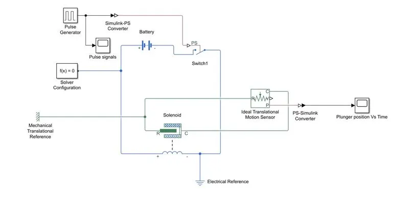
The simulink program is attached in google drive below as doorbellchallenge.slx
BLOCKS USED
1) Pulse Generator: It creates pulse based on some parameters shown below
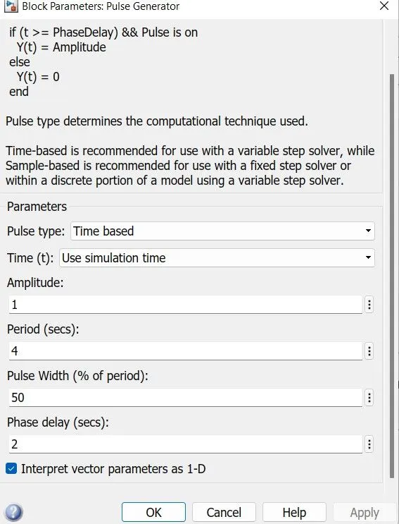
In order to get open switch for first 2 seconds, we use phase delay 2 seconds. After 2 seconds, the switch will close and the circuit is closed and start electromagnetic induction
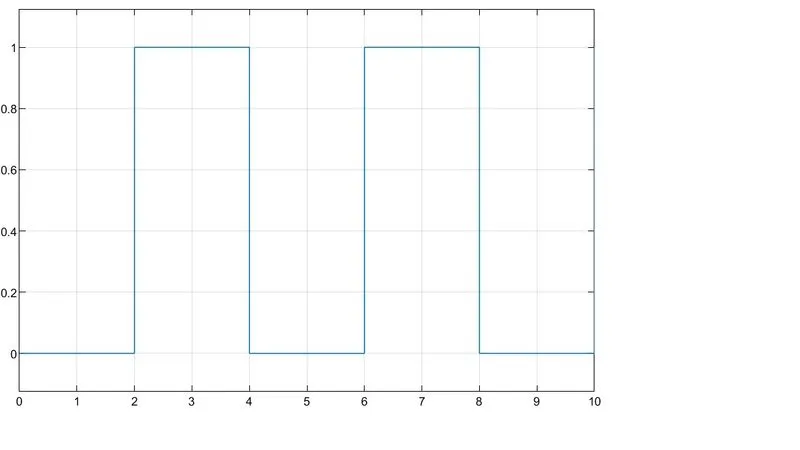
2) Scope(Pulse Signal): To record the pulse from pulse generator. Output is shown below
3)Simulink PS converter: To connect simulink items to physical system
4)Switch: If the external signal is greater than the threshold, the switch will open. Threshold parameter is defined before making connection. By default, it is 0.5
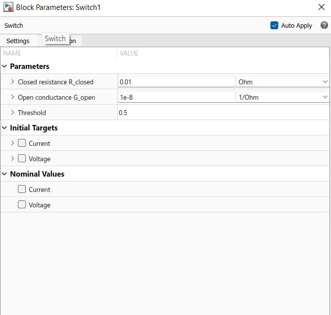
Whenever the pulse signal is greater than 0.5, ie 1, then the switch pass signal
5)Battery: The nominal voltage and internal resistance parameter is set by default. Battery provides voltage and current to the circuit
6)Solenoid:It has electrical and mechanical functions. It has spring coil which produce electromagnetic induction whenever the circuit is closed. As a result,it pulls plunger towards it
7)Ideal translational motion sensor: To detect the motion of plunger.Initial position parameter is 0 m.
8)PS Simulink converter: To convert signals from physical systems to Simulink
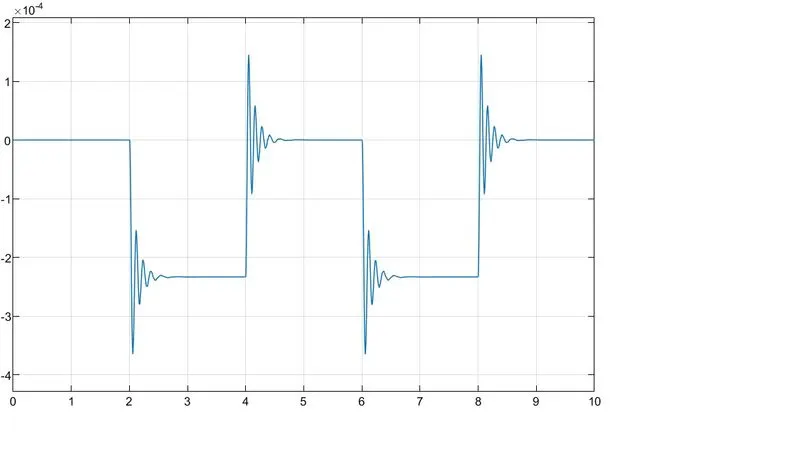
9)Scope(Plunger position Vs Time): To track the motion of plunger
10)Mechanical translational reference:This block represents a mechanical translational reference point, that is, a frame or a ground. Use it to connect mechanical translational ports that are rigidly affixed to the frame (ground)
11)Electrical reference:A model must contain at least one electrical reference port (electrical ground)
12)Solver configuration:Defines solver settings to use for simulation
PROCEDURE:
1)Pulse generator block is used to generate signals as per desired amplitude,pulse width,phase delay
2)Connect the pulse generator with scope block to see the result
3)Connect the pulse generator to Simulink PS converter to connect to electrical system
4)Output from step 3 is connected to switch. The switch will pass the signal based on threshold defined.If pulse signal is greater than 0.5, it will pass signal
5)The switch is connected to a circuit of battery and solenoid
6)The solenoid is then connected to mechanical translation reference and ideal translation sensor. From ideal translation sensor,we sense plunger motion using scope block
7)Whenever the switch is closed, the solenoid induces electromagnetic induction and pushes the plunger towards it
8)Then the plunger hits the bell placed near to solenoid coil
9)When the plunger hits the bell,it breaks the electric circuit and electromagnetic induction stops. Then the plunger moves back to original position
10)When the plunger back to initial position the switch is open and then close after 2 seconds as per the phase delay set in pulse generator.Then the whole cycle repeats again and again producing bell sound after every 4 seconds
OUTPUT OBSERVATION:
It is the observation of scope block plunger position Vs time
Whenever the switch is open for 2 sec, the plunger position is at 0.When the switch is closed for 2 sec,the plunger comes between -1.5 to -3.5 x 10^-4, and rest around -2.3 x 10^-4. This is the moment when the plunger is in contact with the bell.When the electromagnetic induction stops after 2 sec, the plunger moves back to the original position and the switch is open then. the same process is repeating again and again based on simulation time
TASK 2
OBJECTIVE
Use a thermistor to sense the temperature of a heater & turn on or turn off the fan as per the below conditions:
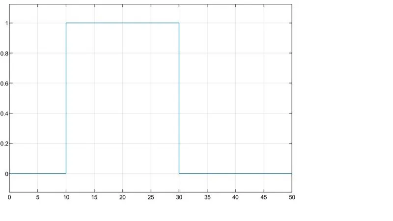
Temperature source: 20 °C from 0 to 10 seconds, 27 °C from 10 to 30 seconds, 23 °C from 30 to 50 seconds
Fan conditions: ON if the temperature above 25 °C, OFF otherwise
BLOCK USED
1) Signal builder:To generate the signals as per the simulation time. The Y axis limit that are defined by me. The signal is custom made which is developed using matlab. The matlab file is attached in google drive as signalcustom.m
2)Scope(Temp Vs Time):To view the output signal from signal builder
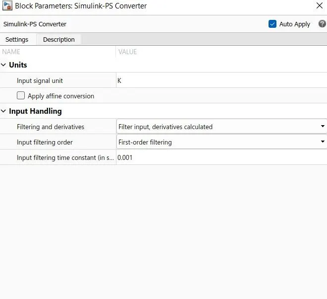
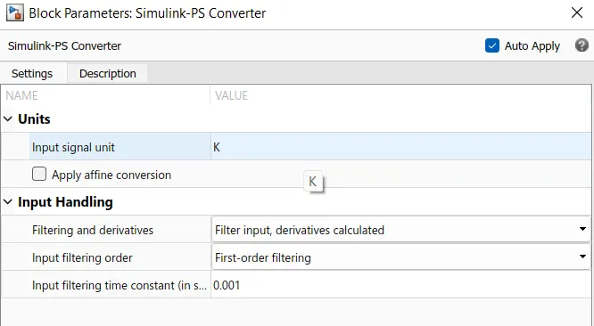
3)Simulink PS converter:To connect simulink items to physical system. The parameters of Simulink PS converter is changed as shown below.The signal unit is K as we are inputting temperature(Kelvin).The filter input are given to get the result in pulse form in Voltage Vs Time scope block
4)Controlled Temperature Source:This block represents an ideal energy source in a thermal network that can maintain a controlled temperature difference regardless of the heat flow rate
5)Thermistor:Thermistors are temperature-dependent resistors, changing resistance with changes in temperature. They are very sensitive and react to very small changes in temperature
6)Resistor:Used to check the voltage across it in an electric circuit. Its defaukt resistance parameter is 1 Ohm
7)Voltage sensor:To check Voltage across resistor(item 6)
8)DC Voltage source:The DC Voltage Source block maintains a time-invariant (constant) voltage across its output terminals, independent of the current through the source.The input parameter of voltage is 12 V
9)PS Simulink Converter:Converts the input Physical Signal to a Simulink output signal
10)Scope(Voltage Vs Time): To note the output voltage against simulation time
11)Constant block 0 and 1: To provide logical input to switch and execute one signal based on threshold limit defined on switch
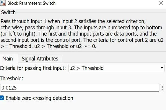
12)Switch:Pass input 1 or 0 of constant block based on threshold setup in the switch.If the signal is greater than threshold limit,it will pass input 1,otherwise input 0.Threshold parameter is defined by used based on Voltage Vs Time scope block.Threshold parameter is shown below
13)ON/OFF Switch scope block:To check whether the output satisfies our requirement
14)Simulink PS converter:Converts the Simulink input signal to a Physical Signal
15)Controlled Voltage Source:Receive Voltage input from previous connection
16)DC motor: To rotate at an angular velocity by receiving the input voltage from controlled voltage source
17)Ideal Rotational Motion Sensor:This block measures angular velocity or angle in a mechanical rotational network. The sensor is ideal since it does not account for inertia, friction, delays, energy consumption, and so on
18)Angular Velocity Vs Time scope block: To measure the angular velocity when the DC Motor is switched on
19)Solver configuration:Defines solver settings to use for simulation
20)Thermal reference:This block represents a reference point in a thermal network where the temperature is equal to absolute zero
21)Electrical reference:A model must contain at least one electrical reference port (electrical ground)
22)Mechanical Rotational Reference:This block represents a mechanical rotational reference point, that is, a frame or a ground. Use it to connect mechanical rotational ports that are rigidly affixed to the frame (ground)
23)Display:Used to display result at the end of simulation time
SIMULINK BLOCK DIAGRAM
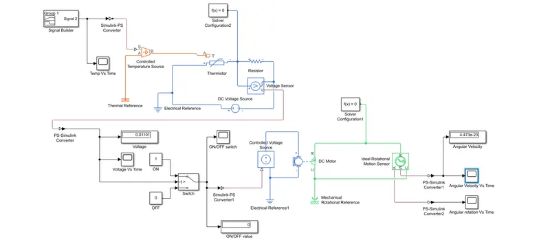
SIMULINK BLOCK CODE:
dcmotorthermistorchall.slx is attached below in google drive. signalcustom.m matlab file is required as its attachment
MATLAB FILE signalcustom.m as an attachment is shown below
clc;clear all;close all;
t=[0,10,10,30,30,50]
temp=[293,293,300,300,296,296]
plot(t,temp);
PROCEDURE
1) Make temperature pulse signal using signal builder.Use matlab file signalcustom.m for creating signals
2)Connect it to Temp Vs Time scope block to view the output
3)Connect the signal builder to Simulink PS converter.Change the parameter of Simulink PS converter as shown below
4)The output of Simulink PS is connected to Controlled Temperature Source(CTS).CTS provide temperature as per the pulse signal obtained at S port.A port of CTS is connected to thermal reference
5)Connect the output of CTS to thermistor. The resistance of thermistor varies as per the output signal from CTS
6)Thermistor is connected to electrical circuit having resistor and DC voltage source in series
7)Solver configuration and electrical reference to be connected to the electrical circuit
8)Connected DC voltage source is having voltage parameter is set to 12 V
9)Connect the Voltage sensor in parallel to resistor to resistor
10)Connect the Voltage sensor to Simulink block using PS Simulink converter
11)The output from PS Simulink is connected to ON/OFF Switch
12)The ON/OFF Switch passes digital signal from constant block 1 and 0 based on threshold conditions. The threshold conditions are defined as per the requirement of this challenge
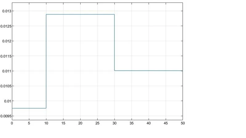
13)Whenever the voltage from electrical circuit is greater than 0.0125, the switch passes 1 digital signal from constant block,such that the fan is ON as per the requirement of this challenge. The fan is ON for 10-30 seconds, because the temperature is greater than 25 *C in this case only as required in this challenge
14)The output voltage from Simulink switch is transferred to physical system using Simulink PS converter
15)Then it is connected to Controlled Voltage Source to use the output voltage from Simulink PS converter, which is used to rotate the DC motor
16)The rotation of DC motor is sensed using Ideal Rotational Motion Sensor and the angular velocity is measured
OUTPUT
1)Output Voltage from voltage sensor
2)ON-OFF signal to switch ON the fan
3)Angular velocity of DC motor in 50 seconds
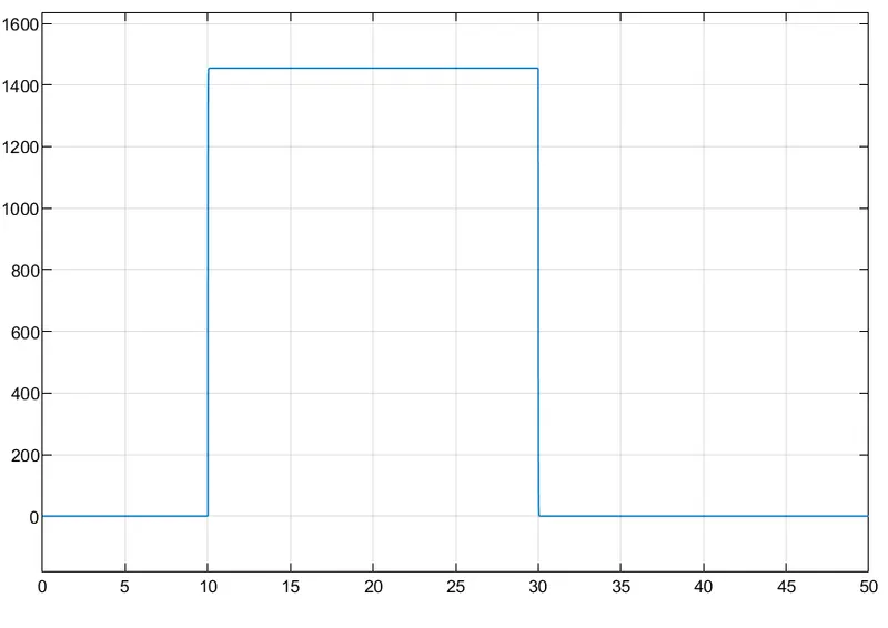
The angular velocity obtained when the DC motor is turned ON is 1454 rad/sec (from figure)
RESULT
The DC motor is switched ON during 10-30 sec and obtained angular velocity is 1454 rad/sec.Thus the Simulink block satisfies the challenge