Week 3 Challenge : CFD meshing on Turbocharger
AIM
For the given model, check for the geometrical errors to make appropriate volumes. Create and assign PIDs. Perform surface mesh with the given target lengths as per PIDs.
- Blade stage-1 = 1 mm
- Blade stage-2 = 1 mm
- Impeller = 2 mm
- Shaft rotor = 1 mm
- Turbo casing = 5 mm
- Compressor casing = 5 mm
- Inlet casing cover = 5 mm
PROCEDURE
The initial model as shown below
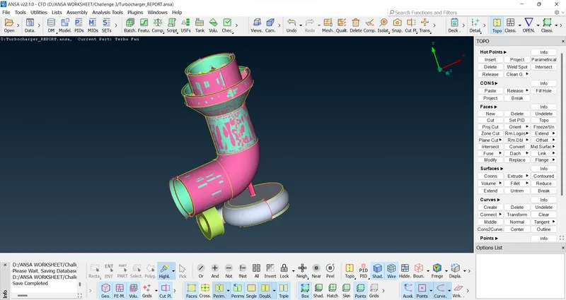
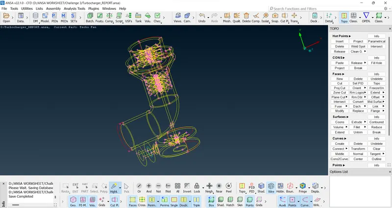
Let's see the wire frame mode
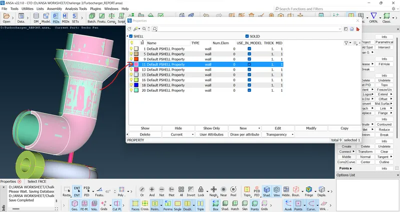
We can see the pink colour element on compressor casing. Also, the glitches can be seen in it. So, it is overlap part. It can be directly deleted. Let's check it in PID and delete it.
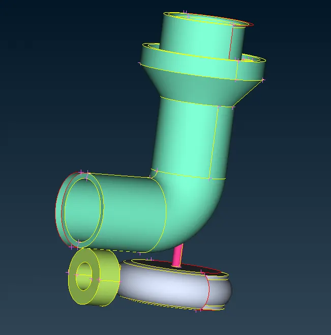
After deleting the figure looks like this
Now we want to clear single coons and intersection errors.
Go to check manager and we can find intersection errors on the outer face. So, we want to clear it.

Go to Intersect under Faces and clear the error of outer surface.
Select the first and second surface as shown below.
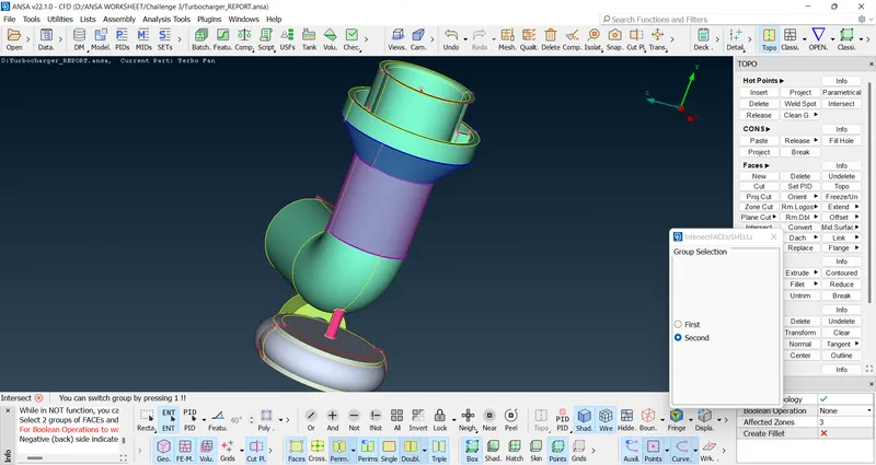
Delete the unnecessary surface by this as shown below
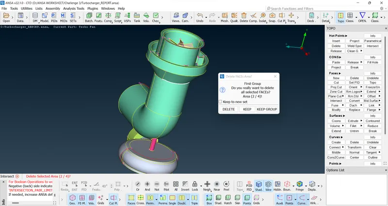
After deleting the unnecessary surface, we can find the unnecessary bendings in the surface as shown below
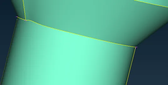
We have to clear this on the entitity using cut option.
Make a cut as shown below and create an entity as shaded below.
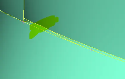
Do it on opposite side of the bending also.
Then delete this unnecessary surface.
Then delete the entity shown below and recreate new surface using coons
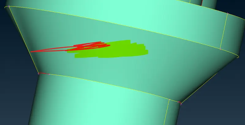
After that, the new surface looks like this as shown below.
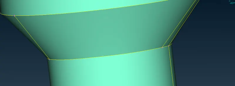
Then clear the geometric error here.
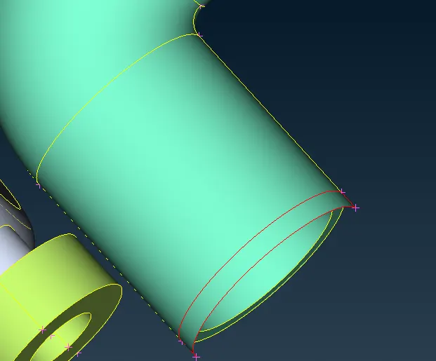
Remove that surface and recreate new surface using coons.The new surface shown below.
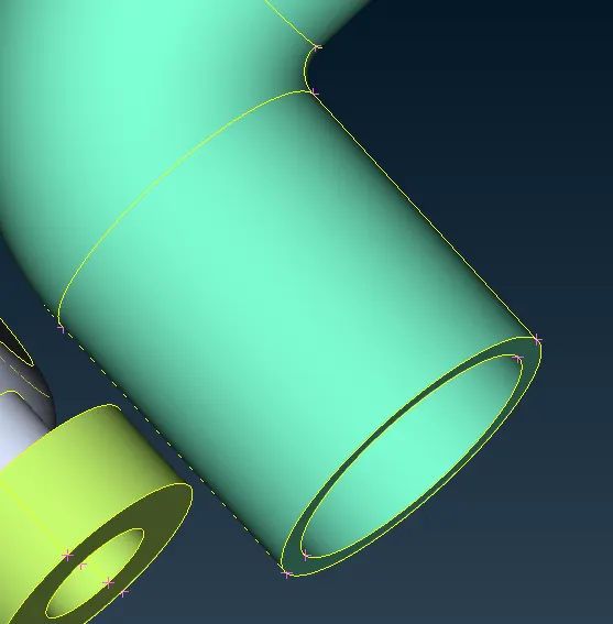
Lets do the geometry clear on Turbo casing using transpose.
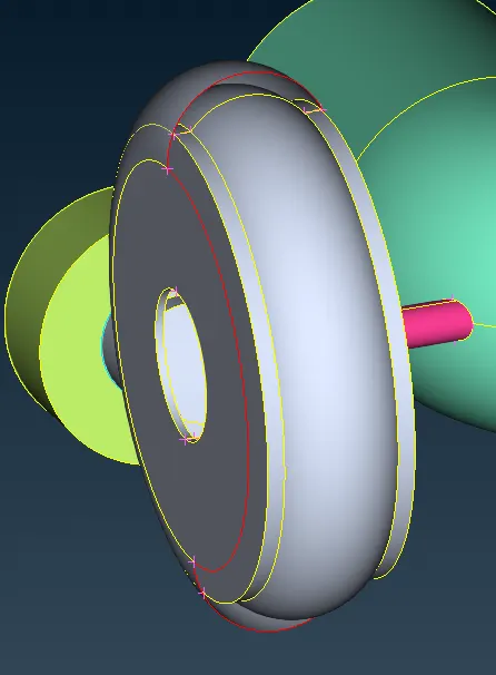

Use mirror 3 point plane as shown below.
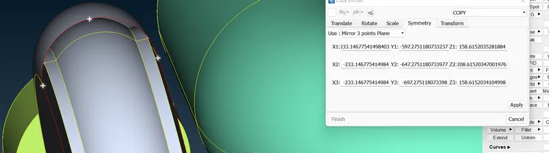
Now, the figure looks like this.
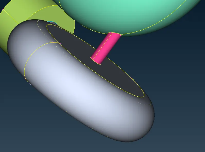
Now, let's clear the single coons on top of the compressor casing.
Use Transform option under curve to create a curve similar to single coon as shown below.
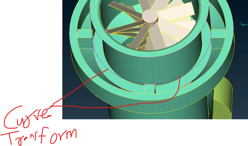
Use coons to create the surface and then delete curves after creating the surface.
Then the surface looks like this.
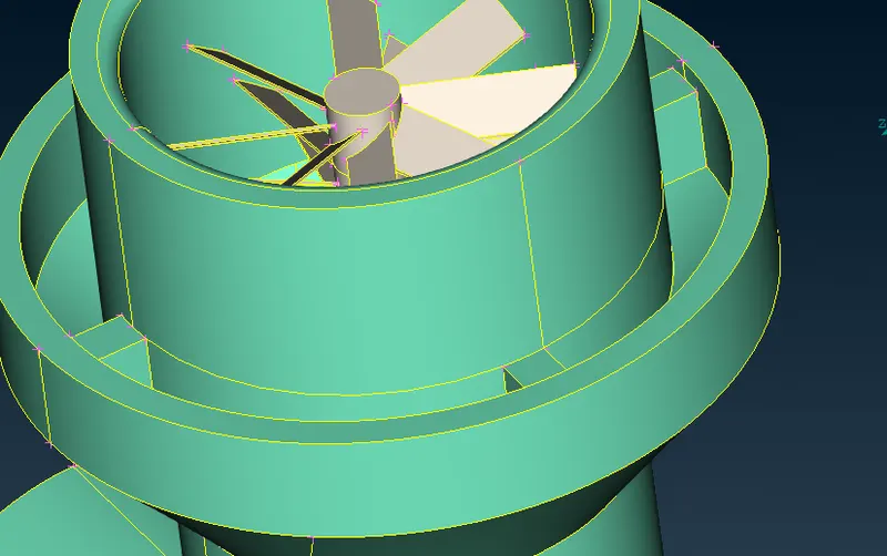
Now, if we do checks we can find lot of intersection errors inside the compressor casing. So, we are isolating the part inside the compressor casing.
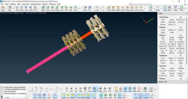
Now, we can find lot of triple cons like this. We are going to solve all this one by one.
The top surface are cleared and looks like this.
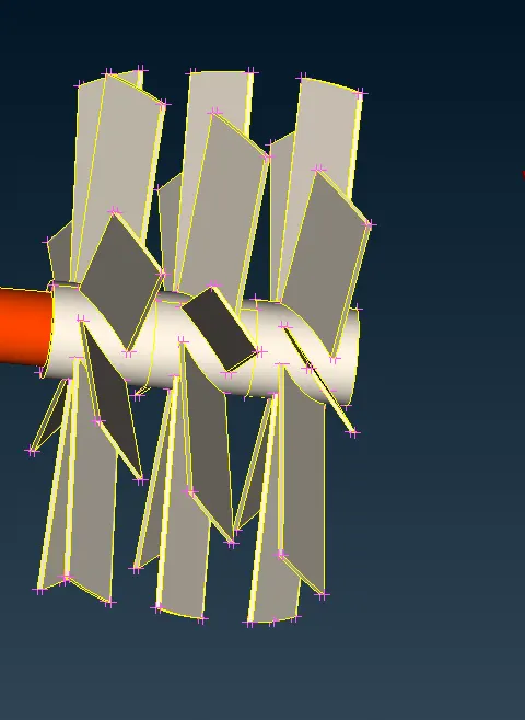
Now, we are going to clear intersection error between these 2 surfaces.
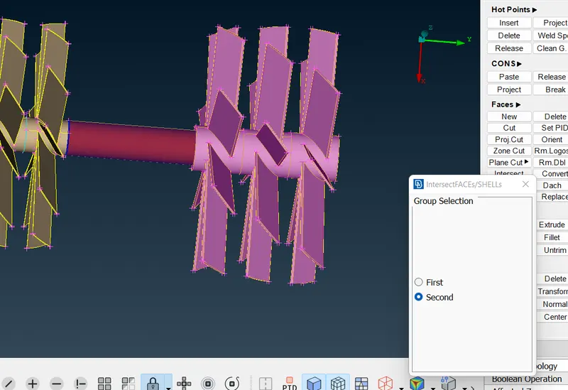
After clearing the intersection error, the top surface looks like this.
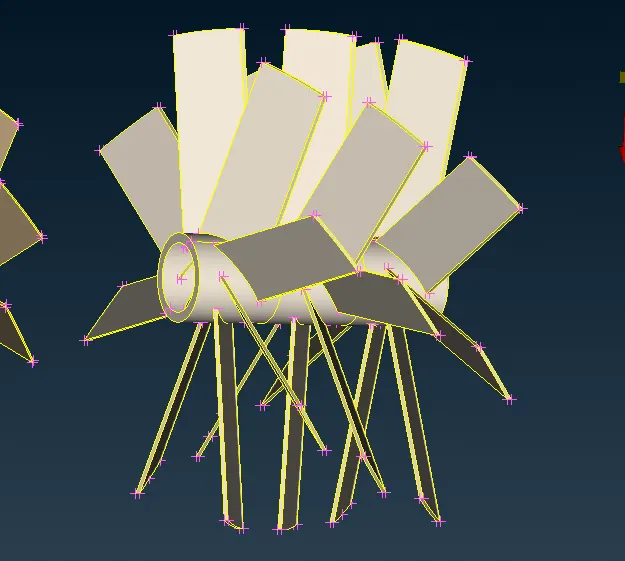
Also, the unnecessary part in shaft deleted and hole is there.
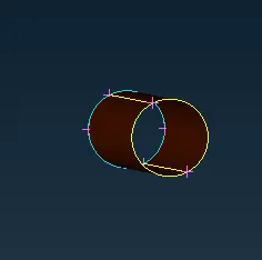
Now, we are going to clear the bottom part.
After clearing, the part looks like this.
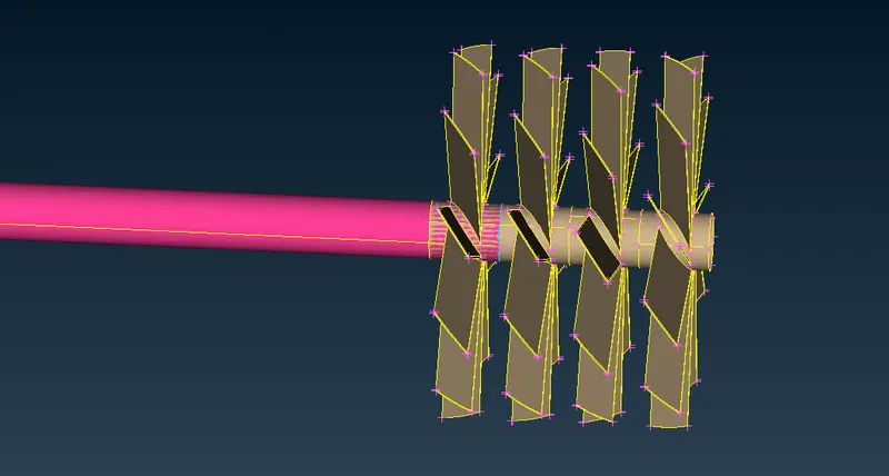
Now, we are going to clear the intersection error as shown below.
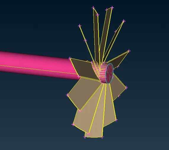
Use project option to delete the unnecessary shaft part overlapped with blade part.
Now, delete this unnecessary part.
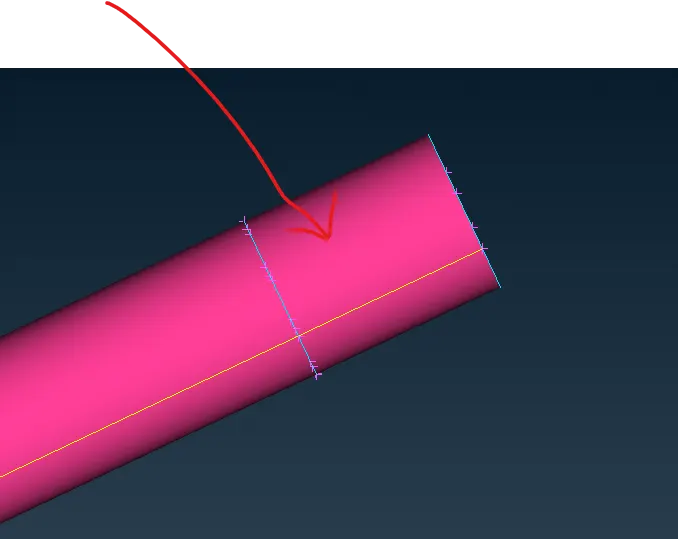
After clearing the shaft looks like this.
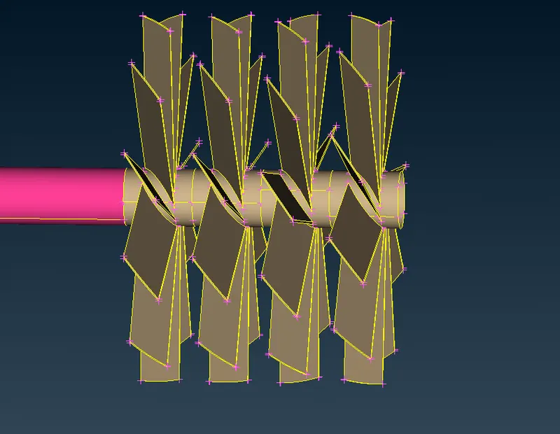
Now, there are 2 more intersection errors which can be cleared using project option.
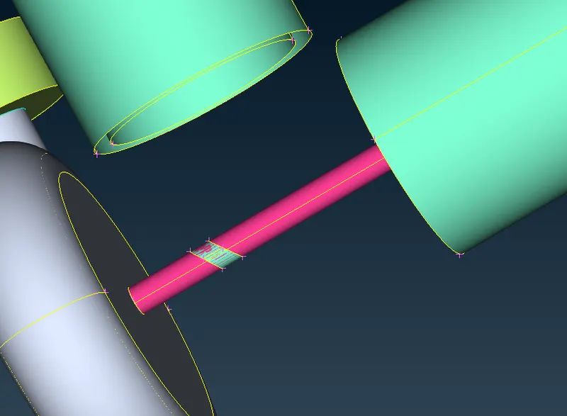
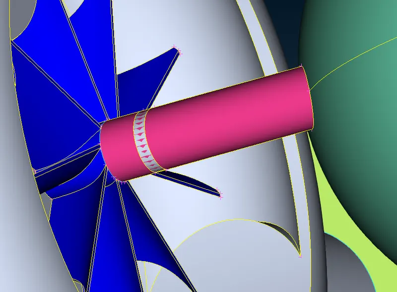
Now, clear the intersection error with turbine.
Now, delete the unnecessary glitching surfaces.
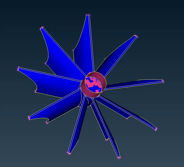
After clearing, the figure looks like this.
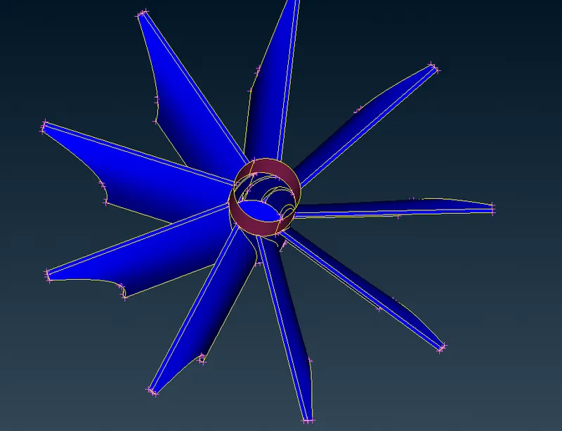
Now, clear the intersection error shown below.
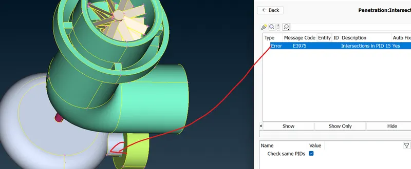
Now, lets close the holes so as to make ready for Volume meshing.
The below holes to be closed.
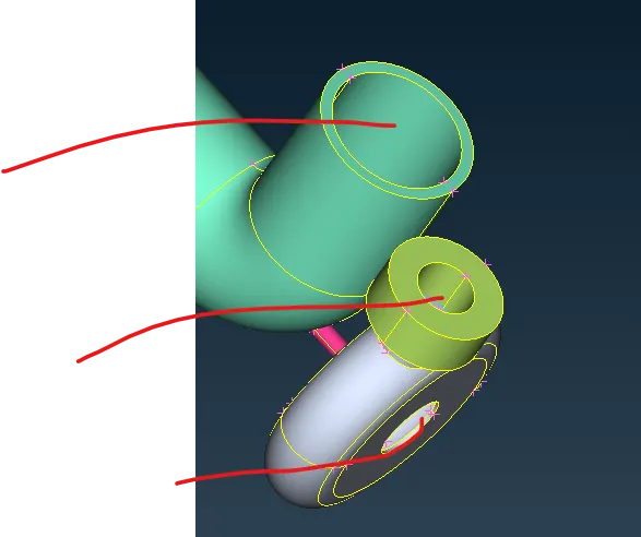
Now, the figure looks like this. Also close the holes on top.
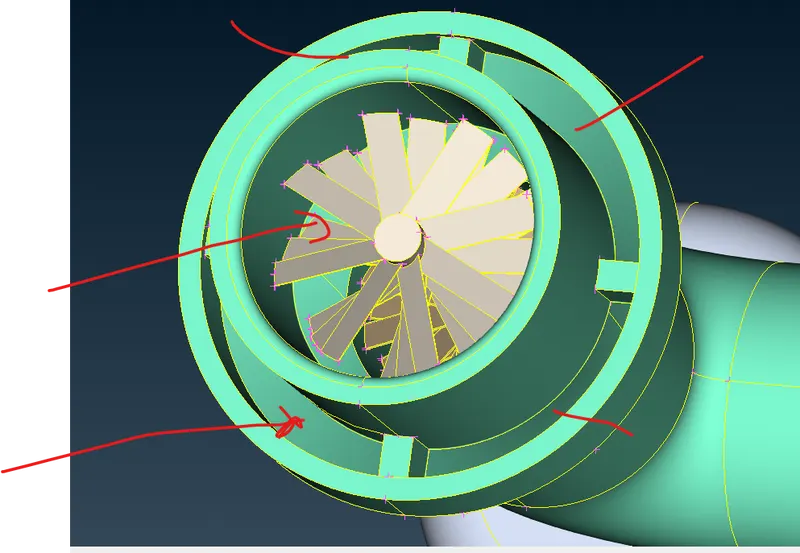
After filling holes, the image looks like this.
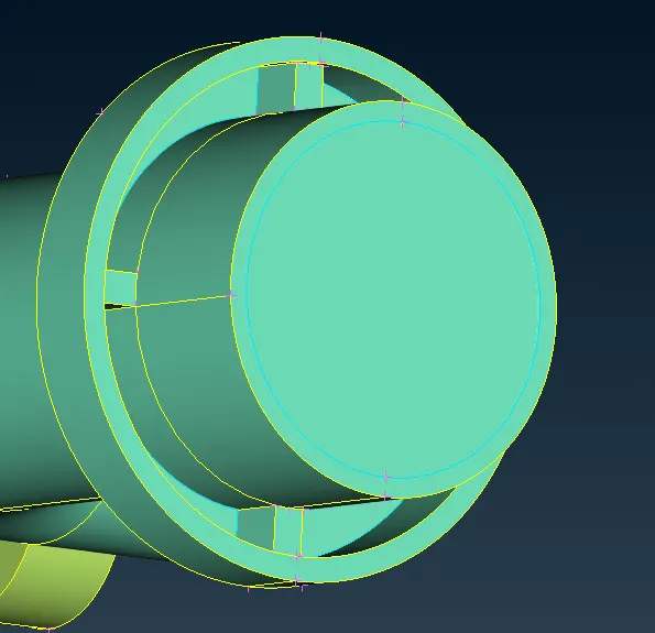
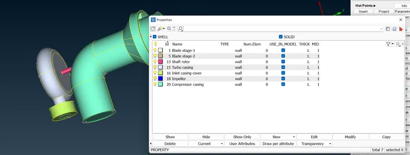
Assign PID now.
Now, go for surface mesh.
Select the 3 PIDs and do the meshing
- Turbo casing = 5 mm
- Compressor casing = 5 mm
- Inlet casing cover = 5 mm
Use perimeter and macros for 5 mm and go for spot mesh.
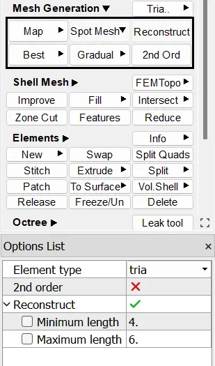
use 4 and 6 as minimum and maximum length.
Use visible to create surface mesh and surface looks like this.
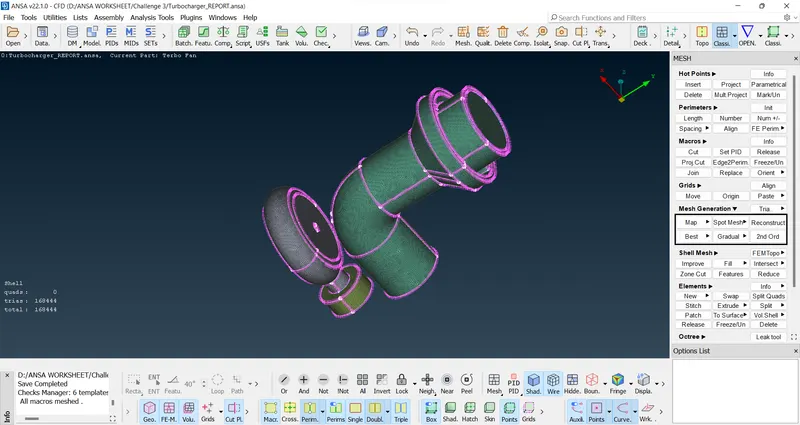
We can use either freeze or use free option later. If we didn't freeze, the meshed entity, at the meeting point of entity with different mesh length, will get erased. We can use free option later to mesh it.
Its better to use freeze option. So, use freeze after meshing.
now mesh Impeller=2 mm.
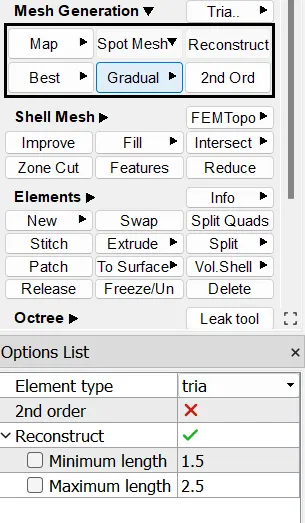
Use freeze after meshing.
Now, mesh the following elements with 1 mm
- Blade stage-1 = 1 mm
- Blade stage-2 = 1 mm
- Shaft rotor = 1 mm
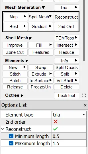
Use freeze after meshing.
Now, all the macros meshed. No unmeshed surfaces.
After that do unfreeze. So, the meshed part looked like this
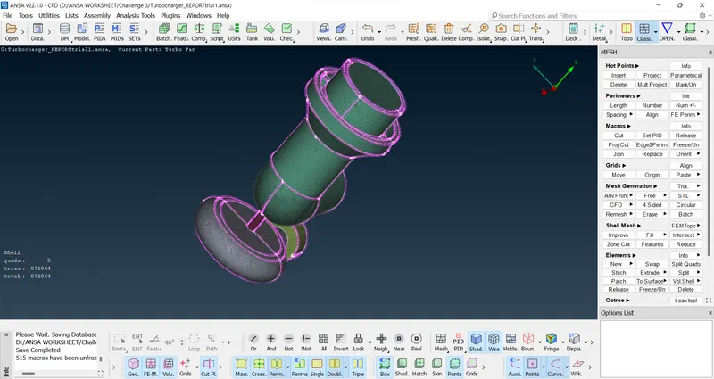
Now, go for Volume meshing. Select Volume meshing from top.
Then the right side appear like this.
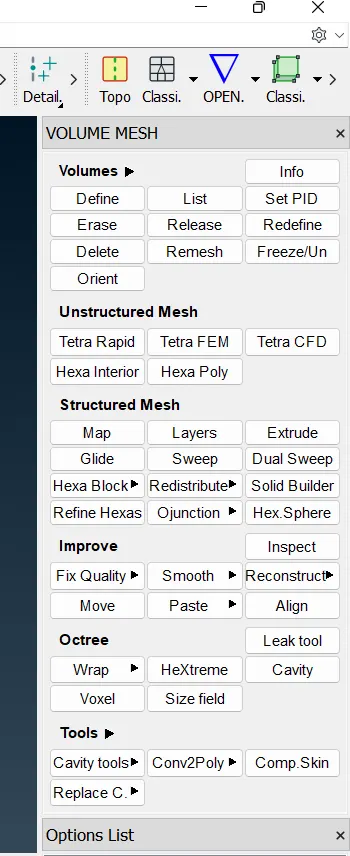
Select Define under Volume
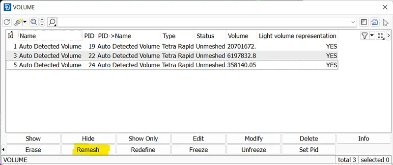
After that 5 auto deteted volumes appear.
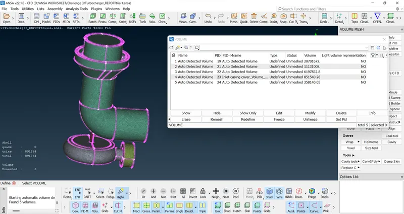
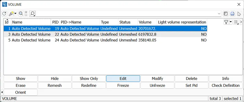
Delete unnecessary volumes from 5. After that, we are left with 3 volumes only.
For internal flow analysis, we consider the volume that can be wetted by fluid. So, we are choosing that suitable volume only.
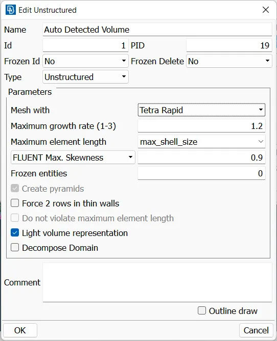
Do Tetra Rapid mesh for all the 3 volumes.
Then click on Remesh to do meshing
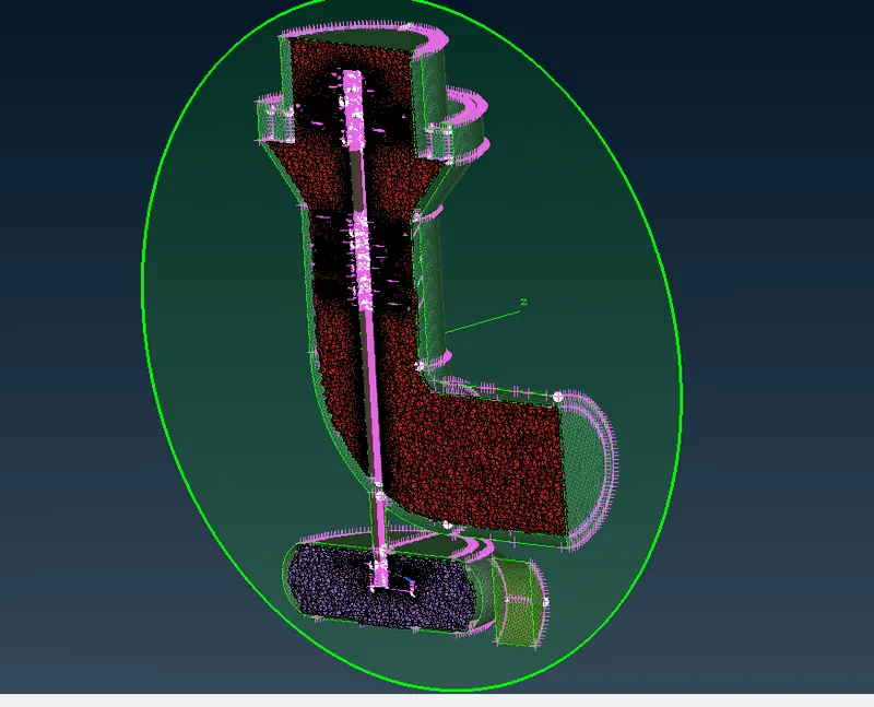
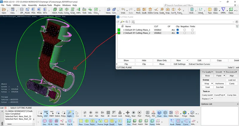
If we want to see the mesh, use cut plane and create 2 plane surfaces.
This is the cutting plane 1
This is cutting plane 2
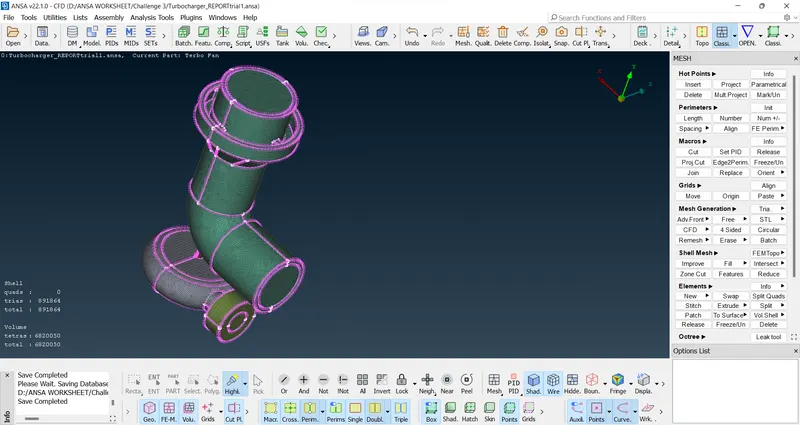
Hide all the cutting plane to go back to the original view.
ATTACHMENT
1) Surface with Auto CFD mesh is attached as https://drive.google.com/file/d/1GW37m_35nwjH_nllo3GNGEkmDy2rTfRv/view?usp=sharing
2) Surface with Spot mesh is attached as https://drive.google.com/file/d/1D4Ee_3d0g8QJ_72p2-VkcdSVK_ua_3Lt/view?usp=sharing
LEARNING OUTCOME
1) Clear geometrical errors
2)Do meshing in a proper way
3)Close all the holes to do the Volume meshing
4)Use cut plane to see the Volume meshing
5)For internal flow analysis, we consider the volume that can be wetted by fluid. So, we are choosing that suitable volume only
CONCLUSION
The spot mesh gives more finer result than CFD mesh for surface meshing