Week 10: Project 1 - FULL HYDRO case set up (PFI)
AIM: To setup and simulate the Full-Hydro Port Fuel Injected Engine.
Introduction:
Port Fuel Injection:
Fuel injection is the introduction of fuel in an internal combustion engine, most commonly automotive engines, by the means of an injector.
Historically, the most widely produced internal combustion engines were of the Port Fuel Injected (PFI) design, where the fuel is sprayed into the intake ports to mix with incoming air. In fact, many new vehicles are still manufactured with this engine design. The fuel injectors in PFI configurations are typically mounted in the intake manifold and the air/fuel mixture is pulled into the cylinder head as the intake valve opens.
Geometry:
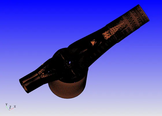
The geometry which is shown below is used for the simulation.
The following are the errors the geometry has.
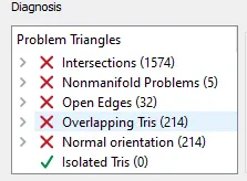
And the final setup of the geometry which has zero errors is...
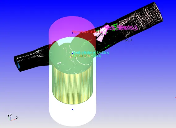
Since we have many errors and single piece geometry we need to divide each part by fence and arc method to specify the parts for further process.
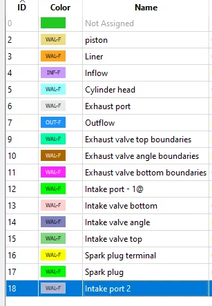
The following are the boundaries which are created.
Case setup:
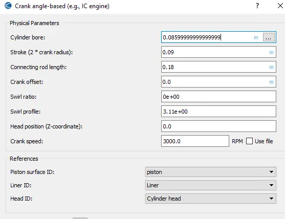
- Application Type:
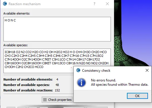
- Reaction mechanism is enabled
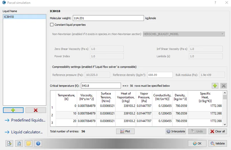
- Parcel simulation is enabled
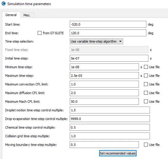
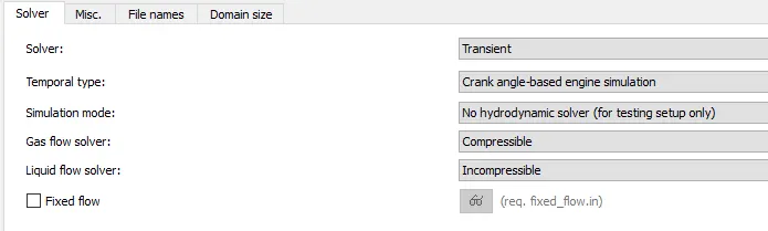
- Simulation Time parameters
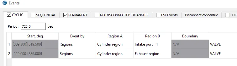
- Events:
- Spray modeling
To define injector, nozzles.
- Combustion modeling
Sage model is enabled
- Turbulence modeling
RNG-k-E
- Source/sink modeling
To give valus of energy, momentum.
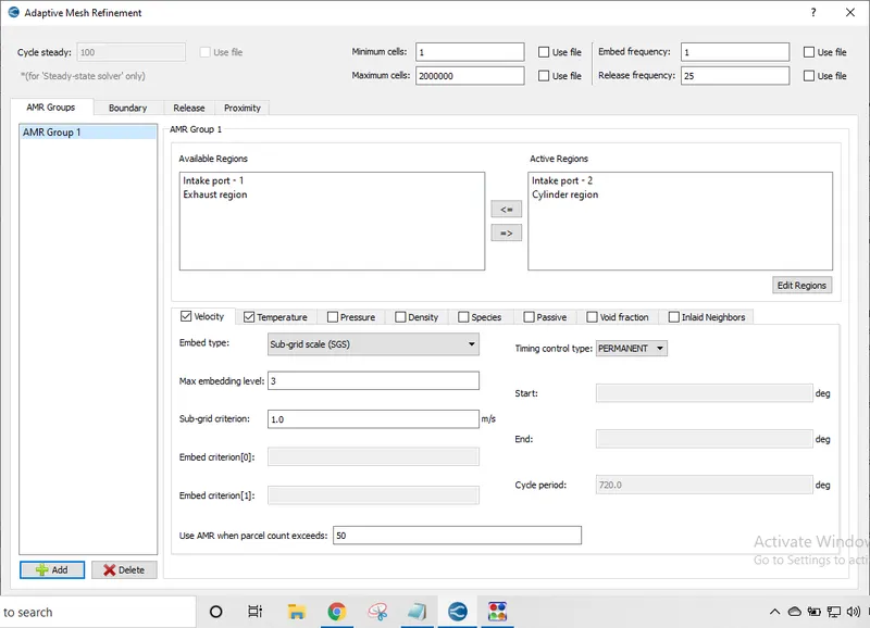
AMR(Adaptive Mesh Refinement):
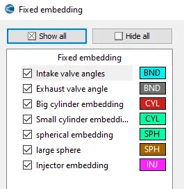
Fixed Embedding:
Results of Simulation:
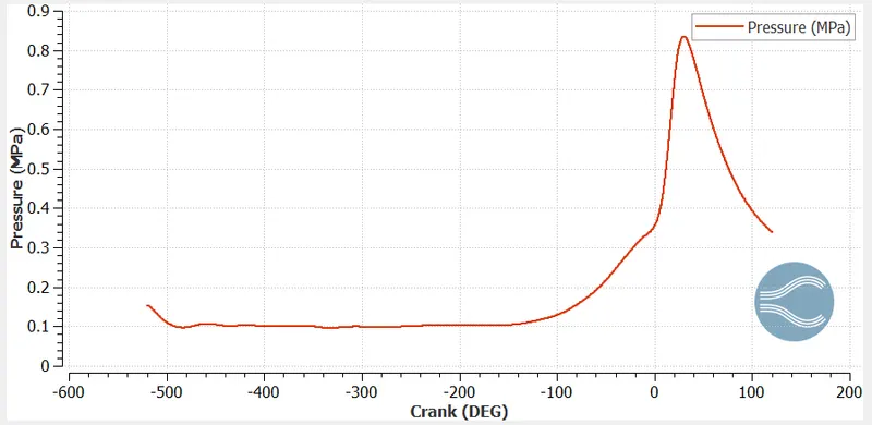
Pressure:
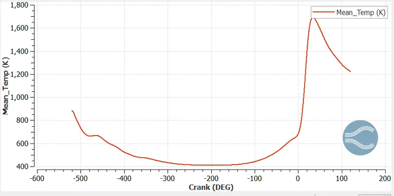
Mean Temperature:
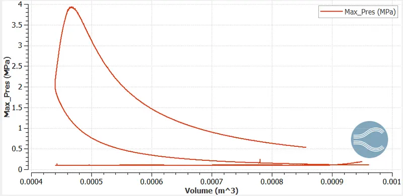
Pressure-volume:
1. Compression ratio:
In a reciprocating engine, the compression ratio is the ratio of volume of cylinder and the combustion chamber when the piston is at the bottom of the stroke and volume of the combustion chamber when the piston is at the top of its stroke.
CR = (Vd + Vc)/Vc,
where Vt = Vd + Vc, Max.cylinder volume, Vd = displacement volume, Vc = clearance volume
Vd = phi*b^2*s/4, b = cylinder bore, s = piston strole length
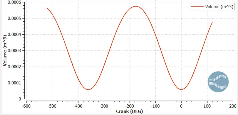
CR = Vt/Vc, from plot Vt = 0.000574203, Vc = 5.75796e-5
CR = 9.97
2. Why do we need a wall heat transfer model? Why can't we predict the wall temperature from the CFD simulation?
Navier-Stokes equations are the governing equations of fluid dynamics and in general can be solved only numerically. Nowadays there are existing a number of commercial and academic codes for this purpose. Most of them are based on finite volume method. In this method the computational domain is being decomposed at a number of small finite volumes or computational cells. This process of decomposition is called meshing. The bodies in the flow are often treated as voids or holes in the mesh. The surface of the body becomes one of the boundaries of the computational domain and the appropriate boundary conditions must be set on it to obtain the numerical solution.
For incompressible flows we have to solve only for momentum equations (i.e. equations for components of fluid velocity vector). For such a case treating a body as a hole in the mesh seems to be a reasonable approach the body is solid, there is nothing to flow within it and in the body-connected frame of reference all the velocities are zero! The wall boundary conditions in this case are no slip(zero velocity at the surface) for viscous flow or slip (zero normal velocity) for inviscid flow.
But for compressible flow case we have to solve one additional energy equation, i.e. equation for temperature or enthalpy. Is it still possible to use the same approach in this case, with the body modelled as a hole in the mesh? It is indeed widely used. In this case we also need a boundary condition for energy equation at the surface of the body. There are number of options depending upon the code, but almost all of them have a so-called adiabatic wall condition. Applying this boundary condition we assume that there is no heat transfer between the body and the flow. This condition seems reasonable in case if we have heat protection at the surface of the body. And we dont have to know anything about the material of the body! But can we trust the wall temperature distribution obtained with such an approach
Modern codes have a capability of solving energy equation both for a fluid flow and for a body (for a solid body it turns to heat transfer equation). Such a problem is called “conjugated heat transfer problem”. For solving this problem the body is no longer treated as a hole in the mesh, it has its own mesh with it. Of course in this case we have more computational expenses and we have to specify additional information about the body thermal conductivity and heat capacity. But with this approach we can obtain the trustworthy results.
Heat conduction equation solved by CONVERGE for the conjugate heat transfer problem.
3. Combustion Efficiency:
It is the ratio of energy released by thr fuel burnt to the theoretical energy of thefuel mass during one complete engine cycle.
nc = Hr - Hp / mf*Qhv,
where, Hr, Hp = enthalphy of reactant,product & Qhv = lower heating value of fuel mass
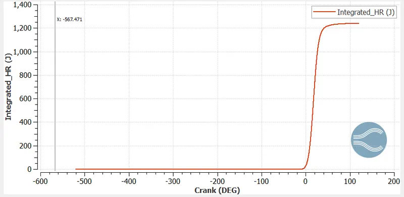
we have Hr = 1241.04 J
lower heating value of IC8H18 = 44.651 MJ/kg
mass of fuel injected per cycle = 3e-05 kg
heat generated per cycle = 3e-05*44.651*e06 J = 1339.53 J
nc = (1241.04 / 1339.53) * 100 = 92.64 %
4. Power & Torque:
From engine performance calculator,
Work = 468.646 N.M
duration = 240.199 degrees
Power = work/sec
RPM = 3000, RPS = 50; 1 rotation = 360degrees
Degree per second= 50 * 360 = 18000
Time = 240.199 / 18000= 0.01334sec
Power= 468.646 / 0.01334 = 35130.8845 KJ 0r 35.14 KW
Power = 2*phi*N*T
Torque (T) = power / (2*phi*N)
N = 50rev/s, power = 35.13KW
Torque (T) = 111.878 N.m
5. Significance of ca10, ca50 and ca90:
The CA10, CA50 and ca90 are defined as the position of the crank angle (deg) at which the cumulative heat release reaches at 10%, 50%, and 90% respectively. The physical significance of CA10 is that it is used to identify the start of ignition in a engine, whereas the CA50 indicates the end of premixed combustion and the start of diffusion combustion of fuel used in the engine. Higher the difference between CA10 and CA50 (CA50-CA10), higher will be the combustion duration and vice versa.
Flame propagation:
https://drive.google.com/file/d/1vr7nlnfkQ_wswwQkmtE5xvZSwfFqTh-x/view?usp=sharing
Velocity:
https://drive.google.com/file/d/1ilokSuL0Y_zsDERDtxcpgpQbcOL4ZyJf/view?usp=sharing