Week-7 : Converting a detailed engine model to a FRM model
Exploring tutorial number 9:
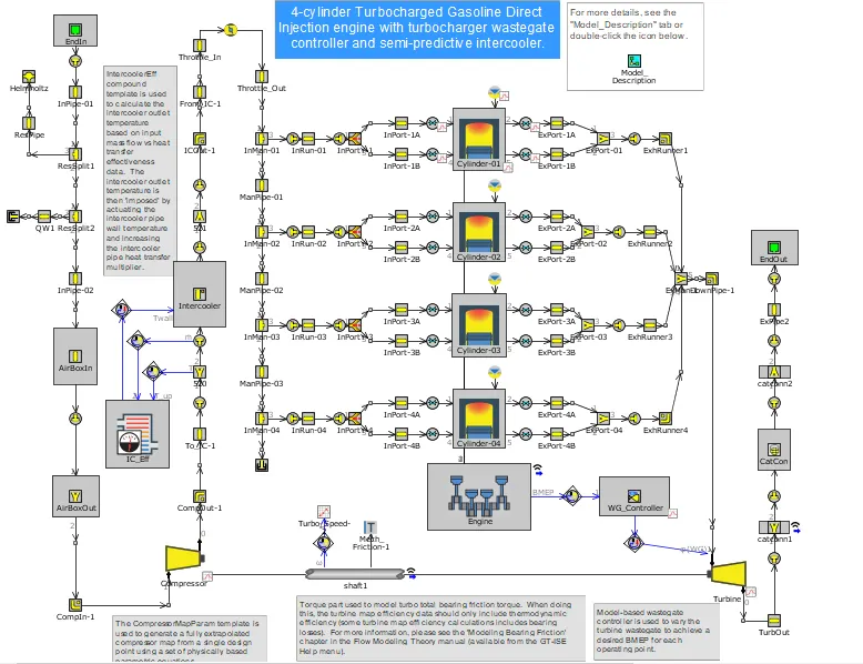
This is a 4-cylinder Turbocharged Gasoline Direct Injection engine with turbocharger wastegate controller and semi-predictive intercooler.
Turbo and Intercooler: The CompressorMapParam template is used to generate a fully extrapolated compressor map from a single design point using a set of physically-based parametric equations.
-The IntercoolerEff compound is used to calculate the intercooler outlet temperature based on input mass flow vs effectiveness data. The intercooler outlet temperature is then 'imposed' by actuating the wall temperature and increasing the intercooler pipe heat transfer multiplier.
-A torque part is used to model turbo total bearing friction torque. When doing this, the turbine map efficiency data should only include thermodynamic efficiency (some turbine map efficiency calculations include bearing losses).
-A turboshaft inertia multiplier is used to impose high inertia for the first 3 cycles when the flow is still stabilizing from the initial conditions. On cycle 4, the inertia multiplier is back to 1 and the wastegate controller starts actuating the wastegate diameter (controller has a 4 cycle dwell).
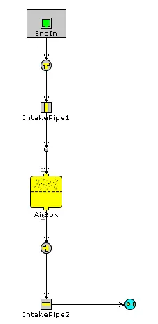
Intake System: Pipe diameters were modified to be realistic for a turbo intake system. The pre-compressor pipes have slightly larger diameters than the post-compressor pipes (due to the increased density after the compressor).
-With the increased post-compressor boost temperatures, the WallTempSolver was used (as opposed to imposing a fixed wall temperature) to calculate the pipe wall temperatures and more accurately model pipe heat transfer.
Exhaust System: A basic turbocharger exhaust manifold is used.
-WallTempSolver with stainless steel material properties (common for high exhaust temperature SI applications) is used in the exhaust.
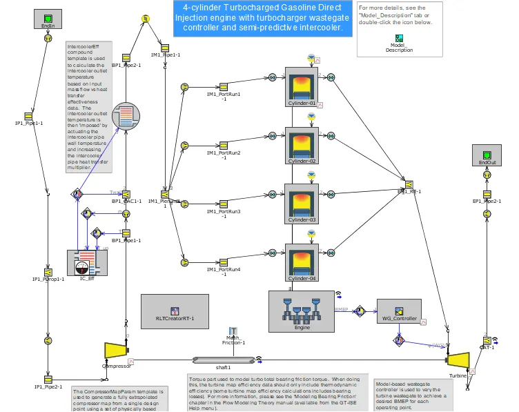
The CompressorMapParam template is used to generate a fully extrapolated compressor map from a single design point using a set of physically-based parametric equations.
A model-based wastegate controller is used to vary the turbine wastegate to achieve the desired BMEP for each operating point.
Building FRM Model:
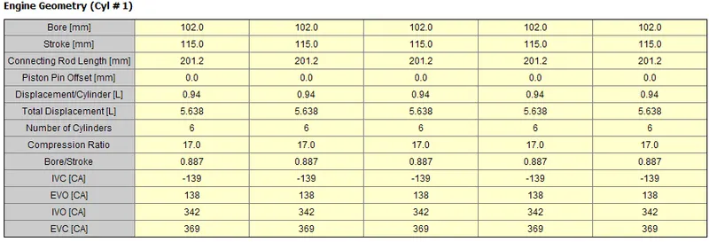
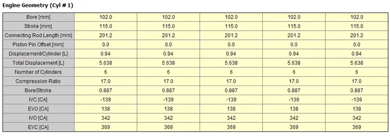
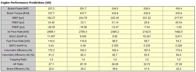
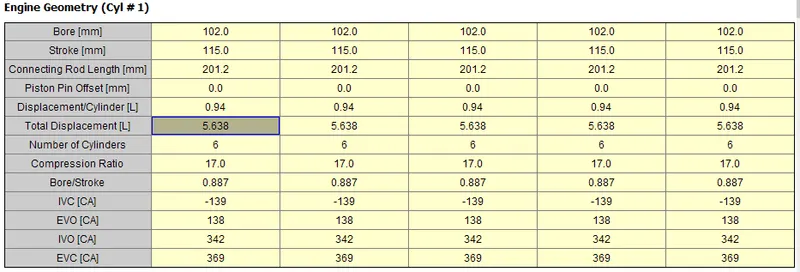
Building FRM model with the following configuration.
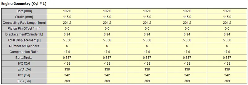
- Bore 102 mm stroke 115 mm CR 17
- No of cylinder 6
- CI engine
- Twin Scroll Turbine
- GT Controller
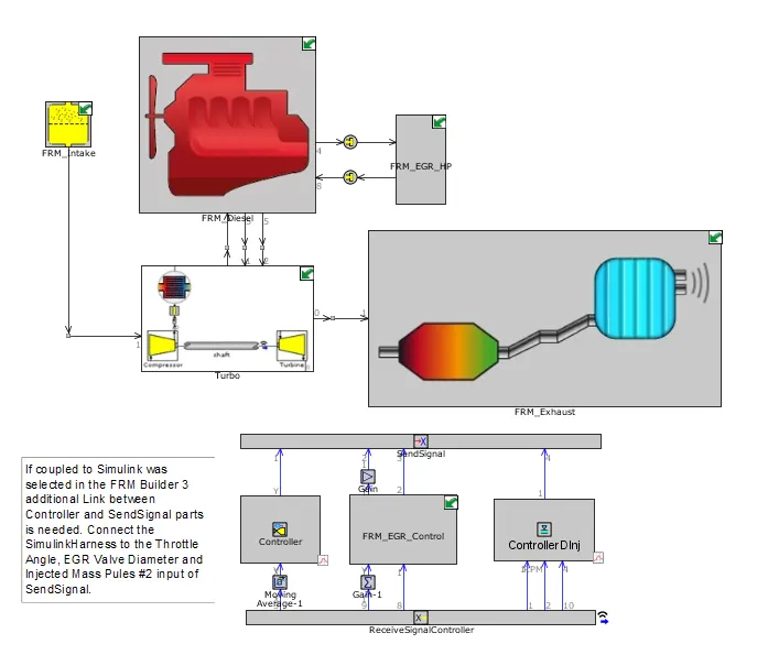
FRM Intake: FRM Exhaust:

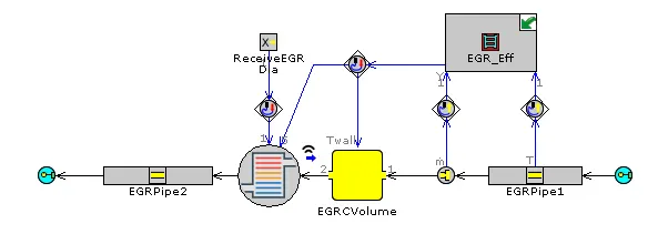
FRM EGR:
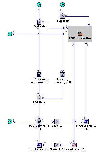
FRM Turbo:
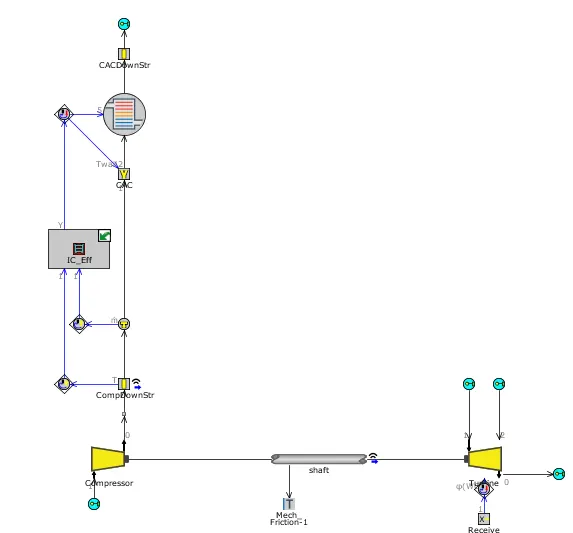
FRM Diesel:
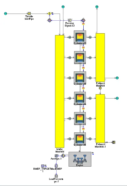
Case-1 to 5:
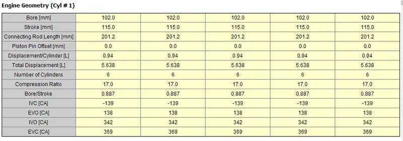
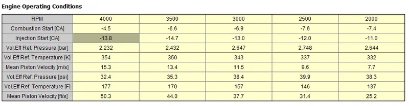
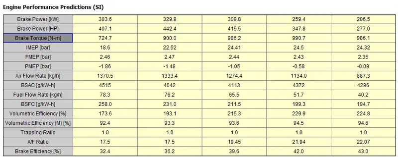
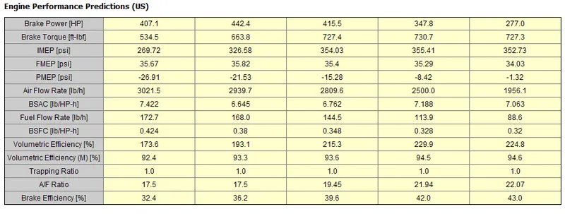
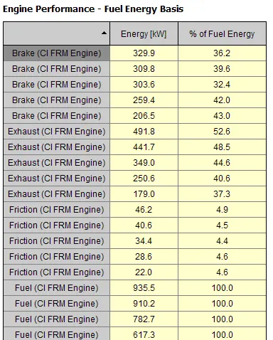
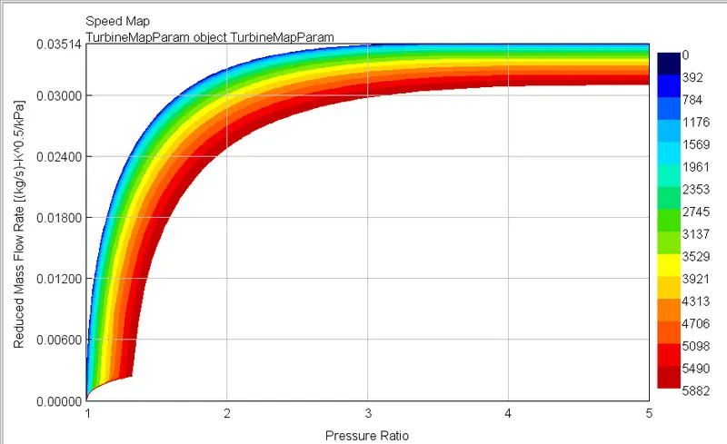
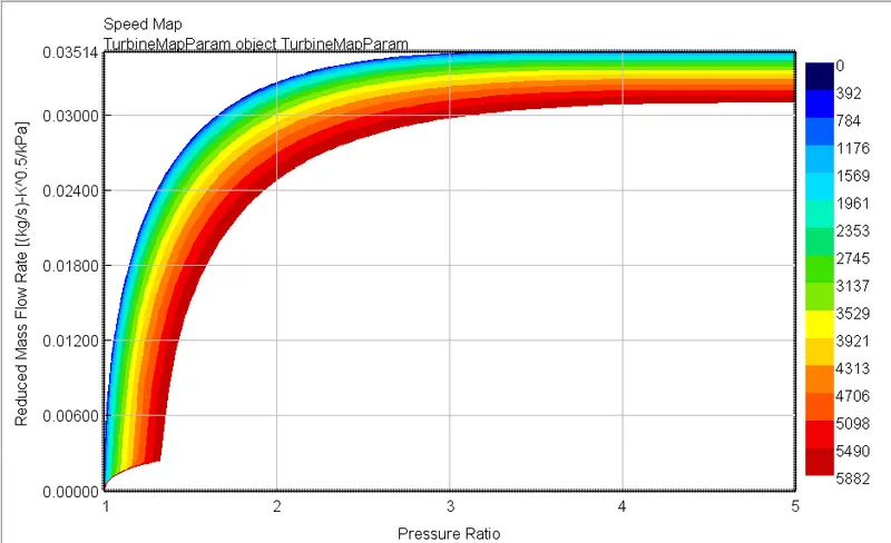
Turbine Map:
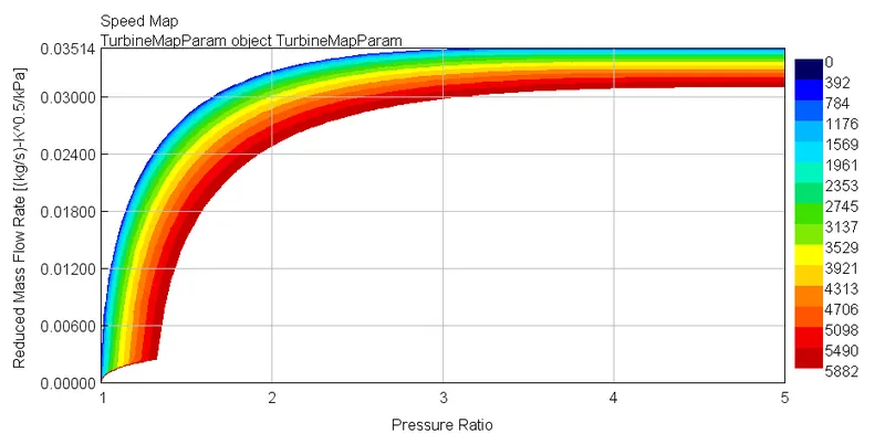
Case-6 to 10:
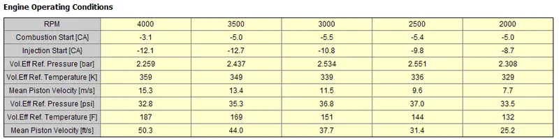
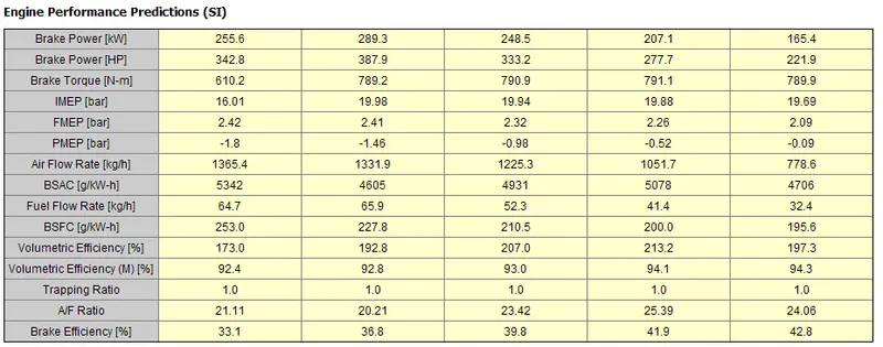
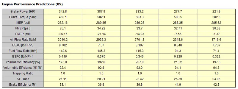
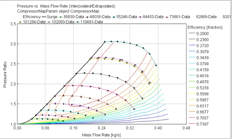
Compressor Map:
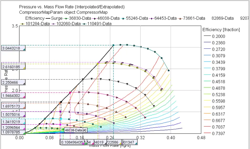
Turbine Map:
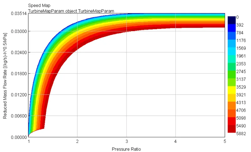
Case- 11 to 15 :
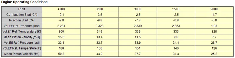
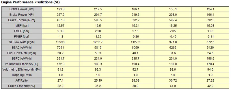
Compressor Map:
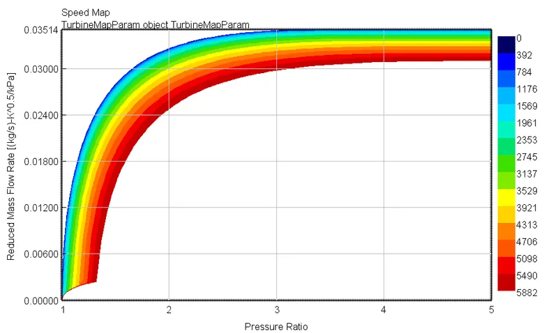
Turbine Map:
Case- 16 to 20:
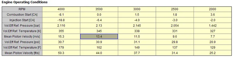
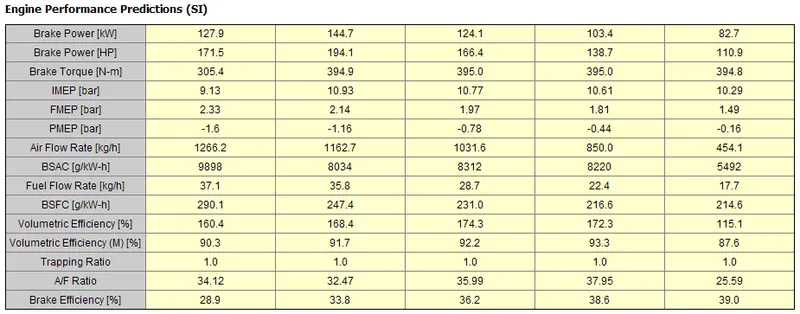
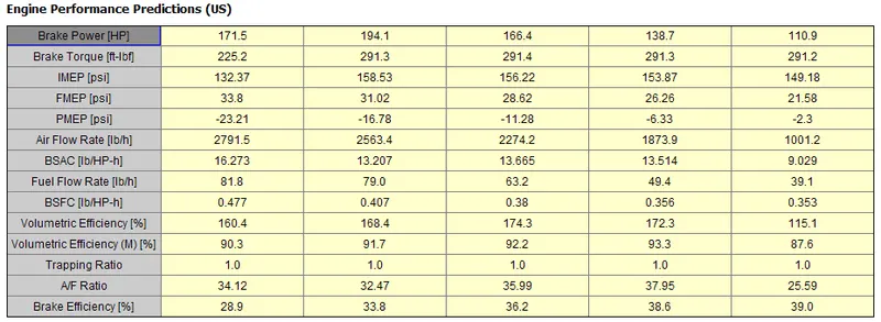
Compressor Map:
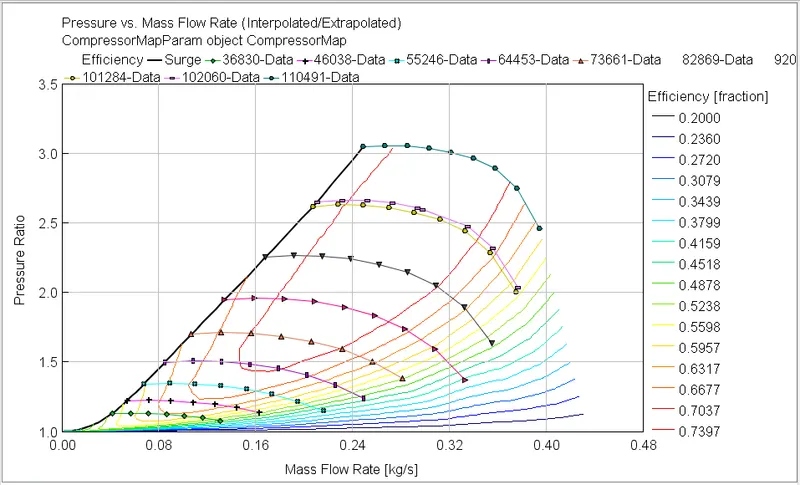
Turbine Map:
Case- 21 to 25:
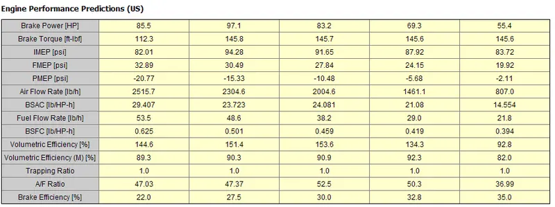
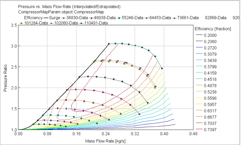
Compressor Map:
Turbine Map: