Week 1 : Exploring the GUI of GT-POWER
1. Explore the GUI of GT SUITE and list down modules available with brief description:
GT-SUITE is the industry-leading simulation tool with capabilities and libraries aimed at a wide variety of applications and industries.
It offers engineers functionalities ranging from fast concept design to detailed system or sub-system/component analyses, design optimization, and root cause investigation.
Why You Should Choose GT-SUITE:
Industry’s Tool of Choice:
- It is recognized worldwide as the Industry Standard for system simulations.
- Used by most leading OEMs and suppliers
- Highly acclaimed
Multi-Physics Platform:
The foundation of GT-SUITE is a versatile multi-physics platform for constructing models of general systems based on many underlying fundamental libraries:
- Flow library (any fluid, gas or liquid or mixture)
- Acoustics library (both non-linear and linear)
- Thermal library (all types of heat transfer)
- Mechanical library (kinematics, multi-body dynamics, frequency domain)
- Electric and Electromagnetic library (circuits, electromechanical devices)
- Chemistry library (chemical kinetics)
- Controls library (signal processing)
- Built-in 3D CFD and 3D FE (thermal and structural)
Modern Software with Unique Capabilities:
- Fusion of 1D and 3D simulation in one tool
- Imports solid models from CAD to create 1D and 3D models
- Performs embedded 3D CFD and 3D FE thermal/structural modeling with all boundary conditions provided by the simulated surrounding complete system
Enterprise-Level Capabilities:
- Integration with leading PLM tools and revision control tools (Siemens TeamCenter, Microsoft Sharepoint, SVN)
- System integration and collaboration tools
- Includes tool-neutral co-simulation platform with FMI support (xLINK)
- Distributed computing
- DOE and optimization
High Productivity and Cost Advantage:
- GT-SUITE includes important and valuable Productivity Tools that are included with all licenses at no extra cost.
- Fast solver makes simulations of large systems practical
- Highly acclaimed Customer Support, is considered the best in the industry
- Highly competitive product pricing.
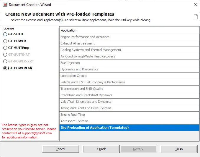
GT-SUITE :
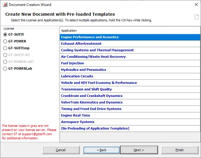
GT-POWER:
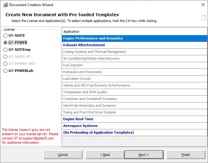
GT-SUITEmp:
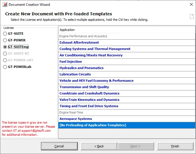
GT-POWERLab :
Productivity Tools:
1. GT-ISE(Integrated Simulation Environment):
GT-ISE is the main interface where models are built, simulation settings are declared, and simulations (both single and batch) are launched. It is an environment where various components are brought into a project map and connected together linking the entire model as a whole.
2. GEM 3D:
GEM3D is a 3D graphical pre-processor that combines building and importing tools used to create 1D GT-SUITE models from 3D geometries.
- GEM3D can be used to build models from primitive components like pipes, flowsplits, shells, catalysts, pumps, etc.
- GEM3D can also be used to import 3D CAD models from other applications, especially GT-SPACECLAIM.
- Once imported it can be used as a “characterizer” to automatically find effective lengths, diameters, bends, volumes, etc. of complex shapes, and convert them into GT-SUITE equivalent parts, such as pipes and flowsplits
- Not only can 3D models be imported and characterized, but additional components can also be added to these models in GEM3D.
- The design is general such that GEM3D can be used for many applications including engine performance, acoustics (intake and exhaust systems), lubrication, cooling systems, hydraulics, cranktrains, and more.
3. COOL 3D:
GT-SUITE is the ideal modeling platform for vehicle cooling analysis. GT-SUITE models can be used to analyze pressure drop, flow distribution, and thermal performance of liquid circuits that cool heat-generating components. GT-SUITE is also used to optimize air flow and heat transfer in the underhood cooling module where heat is rejected to ambient. Construction of GT-SUITE cooling models is enhanced by powerful 3D tools. The GEM3D tool easily converts CAD geometry of flow networks into 1D GT models. The separate COOL3D tool allows for 3D model building and automatic export of underhood cooling module models.
4. VT Design (Valve Train Design) :
VTDESIGN is a graphical preprocessing tool for valvetrain and cam design. It has several capabilities,
which include:
- Cam design tool for creating/modifying cam profiles, using one of many methods: constrained polynomials, intuitive b-spline control of acceleration, or hybrid spline with low order constants/slopes/quadratics connected by splines.
- Dimension-by-dimension visual setup of the valvetrain mechanism. All 5 standard valvetrain types are supported, and profile entered can be cam shape or valve lift profile
- Kinematic and Quasi-Dynamic (Elasto-Kinematic) analysis can be run and viewed directly from the VTDESIGN interface (and updated dynamically with any cam profile changes). CNC cutting tool path can also be calculated from kinematics.
- Spring design tool to create and modify spring shapes, using geometry (axial height vs. helix angle) or force vs. displacement curves. Spring free stroke, solid height, Eigenmode analysis, and fatigue safety factor are all calculated within the interface.
5. GT SPACECLAIM:
GT-SPACECLAIM is a 3D CAD tool included with GT-SUITE. Key applications include:
- Extracting the inner/fluid core (negative) of a solid model
- Importing and converting common CAD formats to GEM3D and COOL3D
- Simplifying geometry to prepare a model for simulation
- Building solid geometry for simulation before production CAD files are available
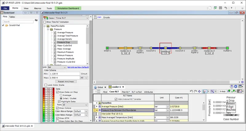
6. GT POST:
Once a simulation is complete, results are viewed in GT-POST, a graphical interface that enables viewing and manipulating of the data collected from the simulation. GT-POST contains the following functions and more:
- Graphically based data post-processing
- Quickly generate 2-D and 3-D plots
- Combine data from different cases, simulations, or tests into a single plot
- Re-usable post-processing templates allow instant cross-plotting of results from different
simulations - Implicit links to ASCII/Excel files with database capabilities for fast and flexible access to
measurement data. - Import or Export data to/from ASCII or MS/EXCEL files
- Perform various math operations on data in all plots (sum, difference, integral, derivative, FFT…)
- Animation of transient processes
- User-definable tabular output of computed results
2. Locate Settings:
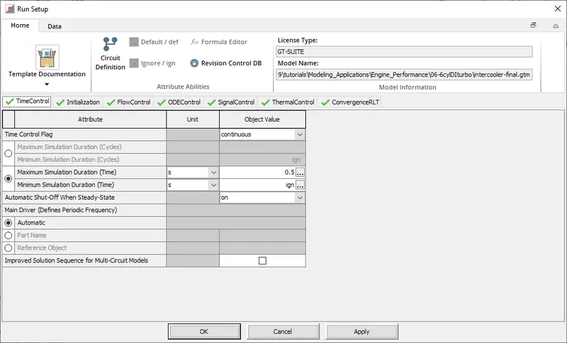
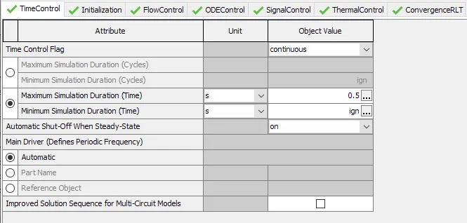
- Time control flag:
Defines the global simulation type with regard to time. One of the following options:
periodic indicates that the model contains at least one circuit which contains a periodic event (i.e. engine cylinder “cycle”) and therefore requires tracking of results with respect to angle over each cycle. Any model that includes an ' EngineCrankTrain', ' CrankAnalysis' , or ' EngineCrankShaft' part should use the periodic option. Note that the simulation duration for a periodic simulation can be specified in cycles or in time, whichever is most convenient.
continuous indicates that the simulation includes no periodic event, and therefore has no need to track results with respect to a cyclic angle. This is the typical setting for models that contain only quasi-steady fluid circuits such as coolant or underhood air. The simulation duration for a continuous simulation is typically specified in time.
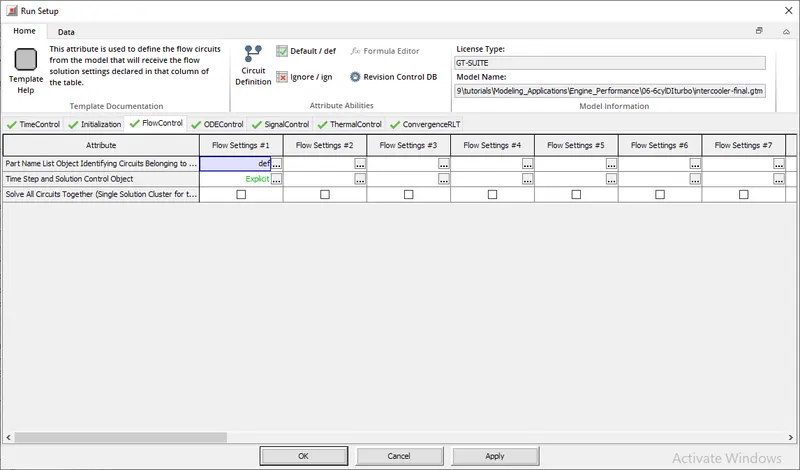
- Timestep and solution control:
Name of the ' FlowControlExplicit', ' FlowControlImplicit', or ' FlowControlQS' reference object that can be used to define the numerical parameters for the explicit, implicit, or quasi-steady flow solver, respectively.
If there are no flow circuits in the model, starting in V2016 Build 2 this attribute may be set to “ign” or left blank (which is a rare exception to the normal requirement in GT-SUITE that all cells must be filled).
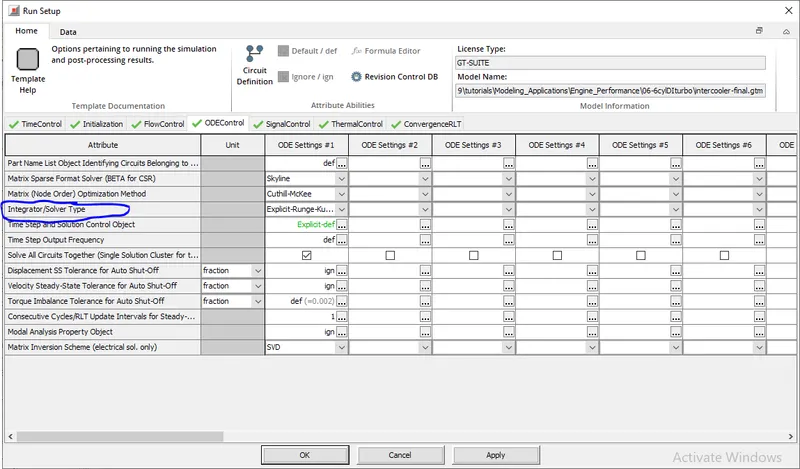
- INTEGRATOR/SOLVER TYPE:
Integrator/solver type used in the time-marching of all ODEs including mechanical, electrical and magnetic libraries. For recommendations based on the application, please see the color-coded table immediately following this text.
- Explicit-Adams-PECE Explicit Adams-Bashforth-Moulton predictor-corrector integration scheme with variable order accuracy. This integrator is recommended for large non-stiff problems, problems with a high maximum time step which have different scales and real time applications. It requires a tuning process in order to optimize its functionality, please contact Email: [email protected] for more details.
- Explicit-Runge-Kutta Explicit Runge-Kutta integration scheme that is 5 th order accurate. This integrator is recommended for non-stiff problems.
- Implicit-Trapezoidal Implicit Trapezoidal integration scheme that is 2 nd order accurate. This integrator is recommended for moderately stiff problems.
- Implicit-H.H.T. Implicit Hilber-Hughes-Taylor integration scheme that is 2 nd order accurate. This integrator is recommended for moderately stiff problems.
- Implicit-Radau2 Implicit 2-stage Radau integration scheme that is 3 rd order accurate. This integrator is recommended for stiff problems.
- Implicit-Radau3 Implicit 3-stage Radau integration scheme that is 5 th order accurate. This integrator is recommended for stiff problems.
- Implicit-S.D.C.3 Implicit 3-stage Spectral Deferred Correction (S.D.C.) integration scheme that is 5 th order accurate. This integrator is recommended for very stiff problems.
3. Explore intercooler tutorial and note down all settings of:
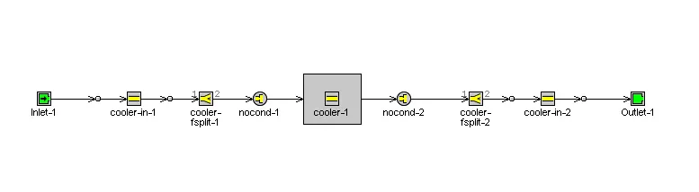
- Run setup:
Time Control:
Initiaization: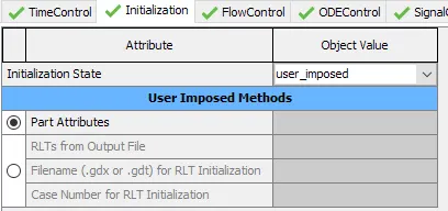
Flow Control:

ODE Control:
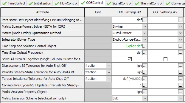
Signal Control:
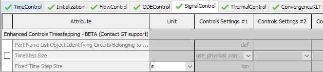
Thermal control:
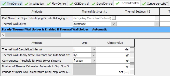
ConvergenceRLT: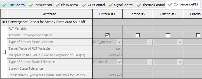
- Advanced setup:
General:
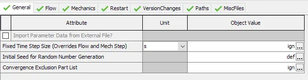
Flow:
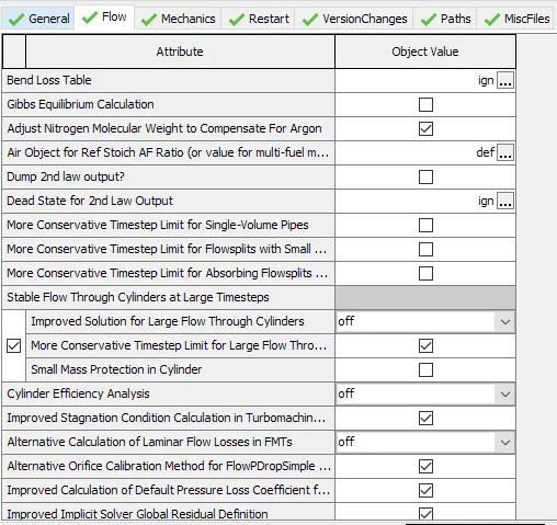
Mechanics:

Restart:
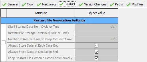
Version Changes:
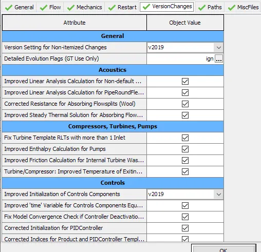
Paths:
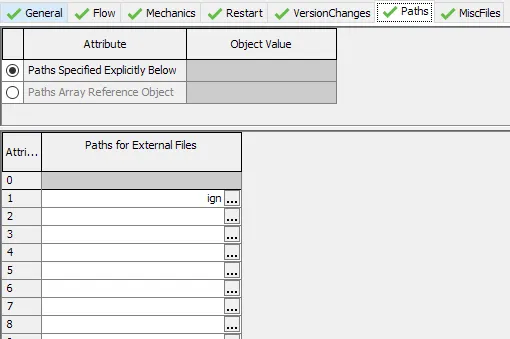
MiscFiles:

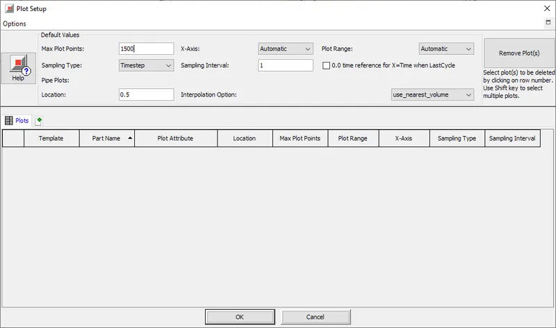
- Plot setup
- Output setup
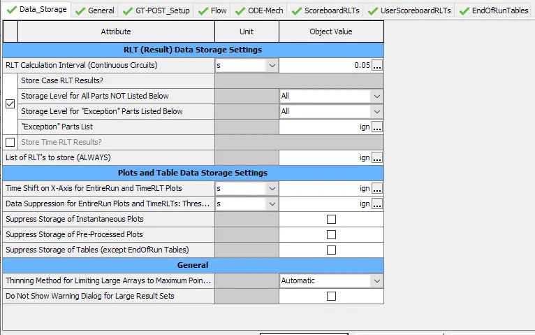
Data Storage:
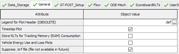
General:
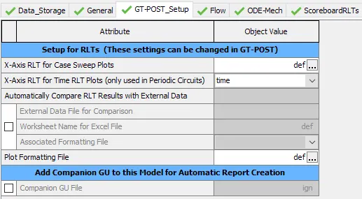
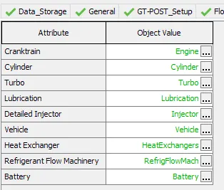
GT-POST_Setup:
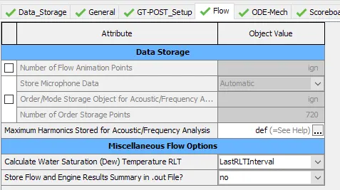
Flow:
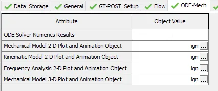
ODE-MECH:
ScoreboardRLTs:
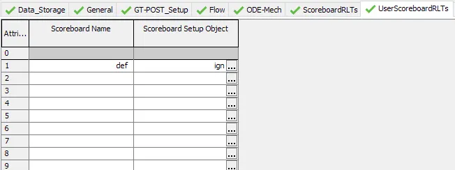
UserscoreboardRLTs:
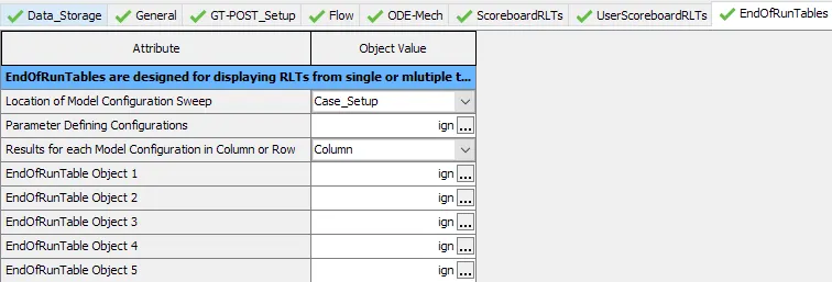
EndofrunTables:
4. Problem:
AIM: To
- Calculate the total heat transfer at Charge air cooler (CAC)
- Calculate pressure drop across CAC
Given
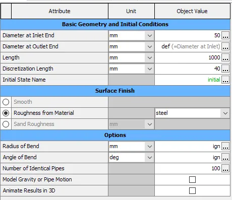
- Diameter of cooler inlet and outlet pipe= 50 mm
- Length of the CAC= 1000 mm
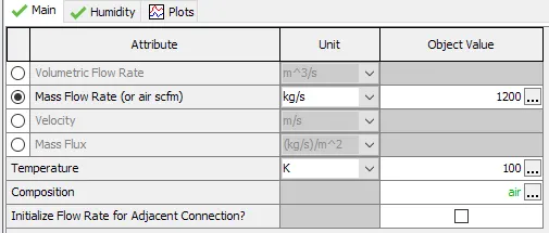
- Inlet mass flow rate = 1200 kg/ h at 100 degC
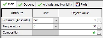
- Outlet pressure 2 bar at 30 deg C
Solution:
intercooler:
inlet-1:
outlet-1:
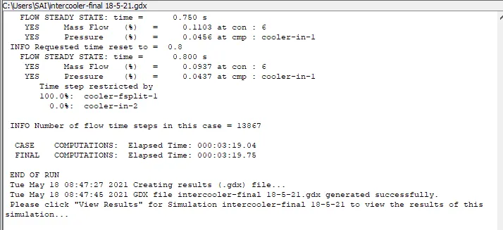
Results:
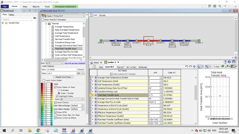
Total Heat Transfer at Charge Air Cooler(CAC):
The total Heat Transfer at CAC is 15.707963 m^2.
Pressure drop across CAC:
The Pressure drop across Charge Air Cooler(CAC) = 1.2334493E-5 bar.