Week 4.2: Project - Transient simulation of flow over a throttle body
AIM: To setup and run transient state simulation for flow over a throttle body.
Procedure:
A CAD model is imported to converge studio.
Check for diagnosis abd assign the boundaries to the region.
Motion details provided to the throttle.
Case Setup:
- Pressure based transient simulation.
- Inlet pressure = 150000Pa
- Outlet Pressure = 100000Pa
- Outlet Temperature = 300K
- End time = 0.01s
- Turbulence model = RNG-E
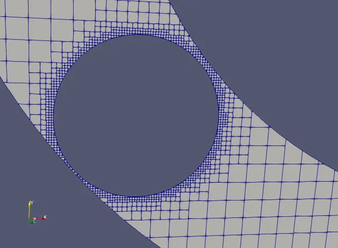
- Base grid size = 0.002m
- Fixed Embedding
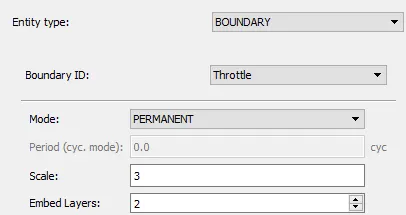
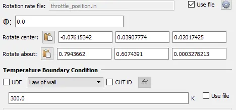
- Rotating angle
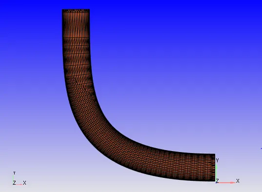
Geometry:
Mesh:
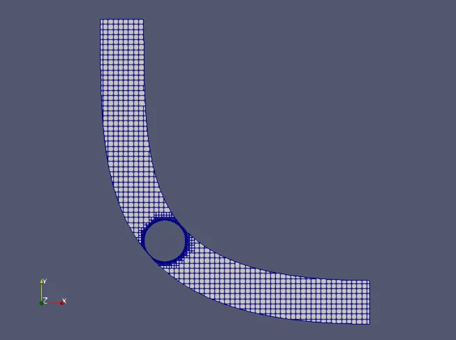
The mesh size is 0.002m.
The embedded details are shown above.
Results:
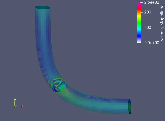
Velocity Contour:
https://drive.google.com/file/d/1Wkmf08_Mc_xeUwy92DMYux1XyC7rx2YJ/view?usp=sharing
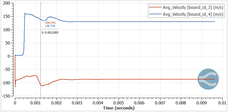
Velocity Plot:
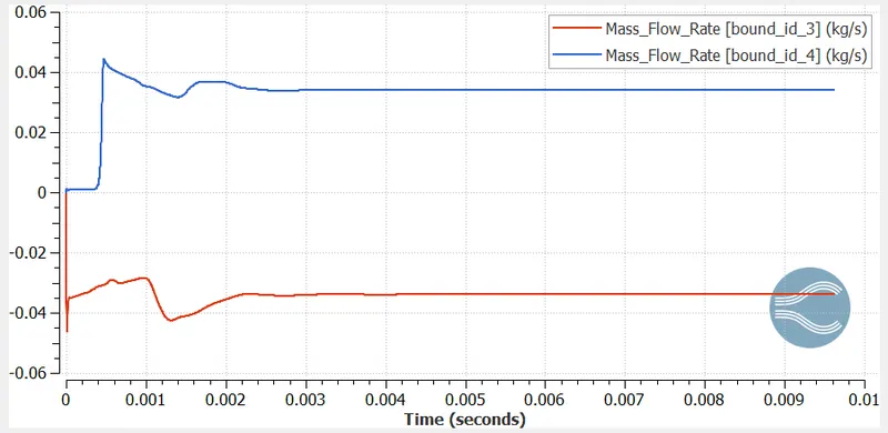
Mass Flow rate:
Gylph:
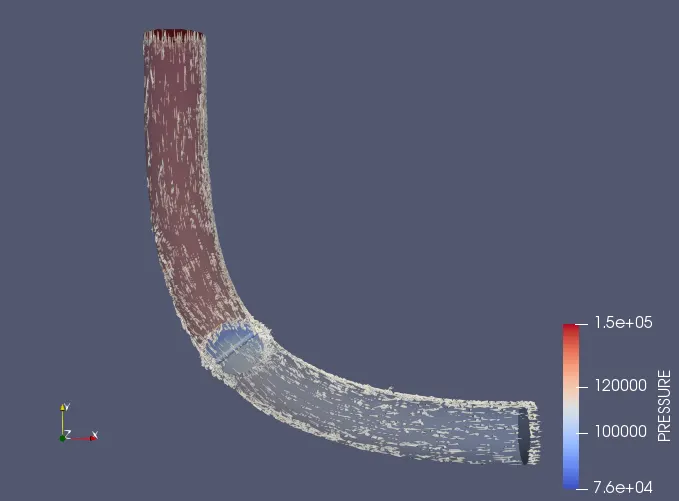
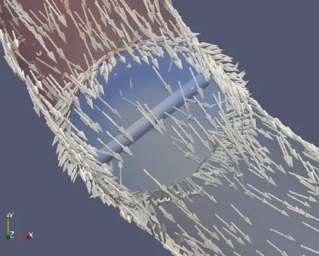
Here, we can see how the flow is at initial state and how the flow is around the valve when simulation takes place.
Pressure Contour:
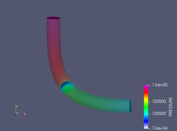
https://drive.google.com/file/d/1auH8dy1OpBmKmfEu7cCpxON-xqQQAIbu/view?usp=sharing
Pressure plot:
Discussions:
Since the given angle is 25 degrees, we can see the flow around the throttle.
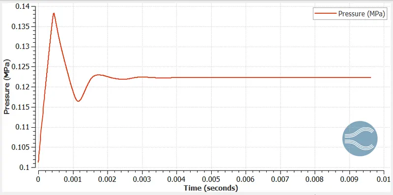
The increase in pressure is observed near throttle area, due to the movement of throttle.
The velocity reduction is observed.
The turbulent flow is increased after the valve.
Velocity and mass flow rate changes from initial to final stage which already shown.