Project 2
AIM:
In order to perform a Structural Analysis with the given CAD Geometry (FRONT WHEEL SUSPENSION ASSEMBLY – Solid Part) by using ANSA. The process involved as follows
- Importing CAD Geometry into ANSA
- Topology Operation
- Performing Geometry Cleanup
- MID Surface extraction for components which had a thickness of less than 5mm. Some Solid Components had thickness nearly satisfying to extract MID Surface was also considered for SHELL MESH
- Applying given Quality Criteria - Presentation Parameters and Meshing Parameters
- Mesh Generation
- QC and Mesh cleanup
- Solid Meshing (Tetra Mesh)
- Check the model for Tetcolapse issues.
- Connections & CBAR (1D Element) on Coil spring
CURRENT PROJECT
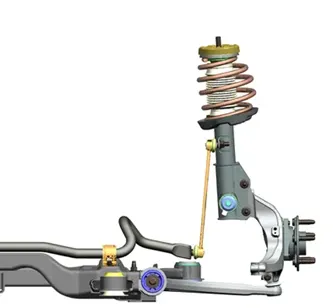
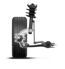
TYPE - Pseudo MacPherson Suspension
The MacPherson strut is a type of automotive suspension system that uses the top of a telescopic damper as the upper steering pivot. It is widely used in the front suspension of modern vehicles and is named for American automotive engineer Earle S. MacPherson, who invented and developed the design.
The difference between a “real” MacPherson and a Pseudo MacPherson suspension is the addition of a lower wishbone. Thus, the guidance of the wheel plane is no longer provided by the lower arm and the anti-roll bar but by the lower wishbone. The advantage of the Pseudo MacPherson is that you can choose to not use an anti-roll bar. This reduces production costs and the weight of the suspension. For light vehicles, the spring stiffness may be sufficient to ensure proper maintenance of the body roll. If an anti-roll bar exists, then it is attached to the spring-damper via a rod.
ADVANTAGES
- Easy assembly
- Ratio cost / performance
- Mass
- Lateral dimension
DISADVANTAGES
- Vertical dimension
- Friction
- King pin offset
- Limited possible settings
The Pseudo MacPherson suspension is the best compromise between cost and performance. This suspension is one of the most used in the vehicle segments like AUDI A3, SKODA FABIA etc.
PROCEDURE:
Import the CAD Geometry into ANSA
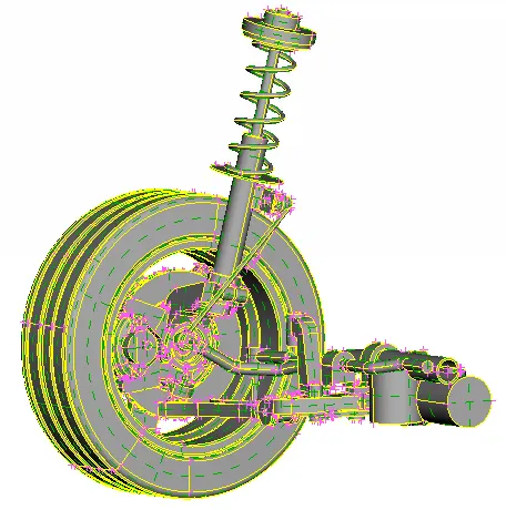
So, here we have the FRONT WHEEL SUSPENSION ASSEMBLY which is a Solid 3D Part (hollow inside). Since it is cross-sectional – Thickness can’t be measured. But some Solid Components had thickness nearly satisfying to extract MID Surface.
TOPOLOGY OPERATION
The Topology is used to recover the results of (Hot Points – Release) and (CONS – Release) functions. It is also used to recover the Topological conditions of a Face that was undeleted by the (Faces – Undelete) function.
Since the Topology is done already, we start with the Geometry cleanup.
GEOMETRY CLEANUP
Geometry cleanup is done in order to get a better Mesh flow.
Before that we’ll refine the model with 1mm. To do so, Go to MESH - Modules > Perimeters > Length. Now Length perimeter pop-up appears. Window select the whole Geometry and middle mouse click to set perimeters length of 1mm. Do the same for the Macros.
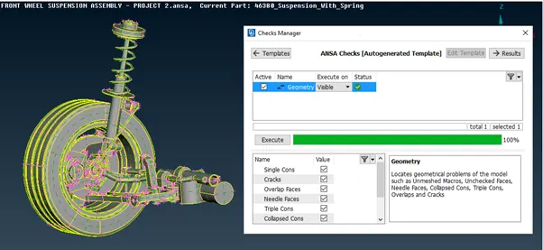
Geometry cleanup is done in order to get a better Mesh flow. To do so, Go to Checks Manager > Geometry. Hit on Execute.
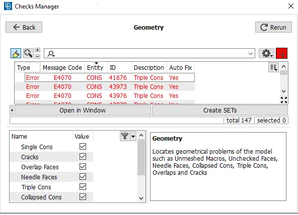
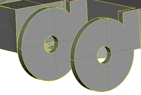
Here, we can see on the Geometry check pop-up that ANSA is showing some errors on the CAD Geometry. The errors are Triple CONS and Single CONS. Since it’s a Solid Part we perform a manual fix to avoid further issues. Select all the Triple CONS errors and hit show only. Now ANSA shows only the area where we have Triple CONS formation. Go to > Neighb > 1st Level which will bring the neighbor area visible. Do the same to fix Single CONS.
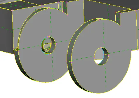
Above Fig. with Triple CON error with surface deformation
Below Fig. with error and surface fixed.
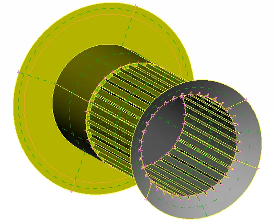
Above Fig. had Single CON error and surface missing, which has been fixed.
Again do a Geometry check, where ANSA shows no error. Hence the Geometry is clean for Meshing.
Surface Cleanup
Remove unwanted hot points and Construction lines throughout the Surface. And Divide the surface by creating construction lines. To do so Go to Modules > Cut and Faces > Datch Divide Face on necessary areas to save time. Surface Cleanup process lead us to a Good MESH flow.
“Challenge faced” to do surface cleanup on the rotor ventilating slots
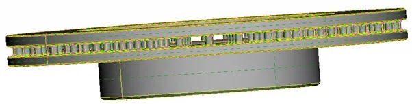
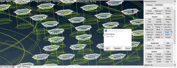
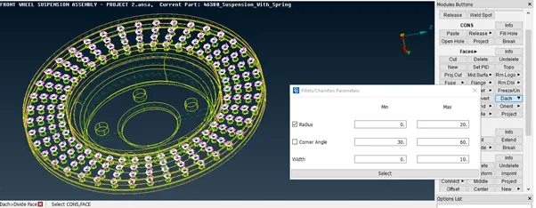
Window select the whole fillet of the ventilating slots and do a Datch Divide face under Faces Modules. Since the fillet had a linear surface the Datch Divide command worked well. A Time saver. And Manual work done on removal of unwanted construction lines.
Rename PID with respective Part Name
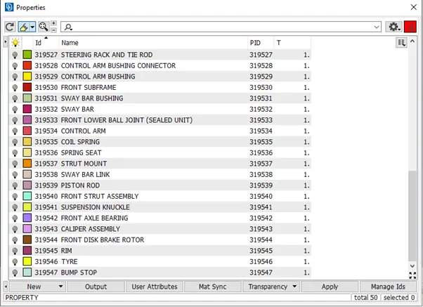
Understand the components and Name each part of it in an individual PID.
To do so, Use (!NOT) command and select the surface of the FE part with PID reg ON. So that the particular part is selected. Then, on middle mouse click selected entities that will remain visible. Now TOPO Modules > FACES > SET PID. Window select the visible Faces/Shell and on confirmation the PID Tab popups. New > PSHELL > PART NAME > OK. Similarly do the same for the other parts. The below Fig. shows the individual PID for each part.
MIDSURFACE (for components which has a thickness of less than 5mm)
Some Solid Components had thickness nearly satisfying to extract MID Surface was also considered for SHELL MESH
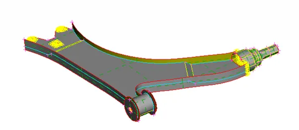
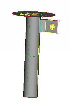
The MID Surface extracted components are the CONTROL ARM & THE FRONT STRUT. Measure the thickness on the edge perimeters. Each one had variable thickness.
To take Mid-surface Go to Modules - and Faces > OFFSET then FEATURE AREA SELECTION. Also TURN ON Cross Hatches. Now select the middle surface of the Geometry and middle mouse click to take an offset. An Offset value pop-up appears. Set the Offset value. Since the Offset direction is on Z Axis we give the value as Negative to get the offset exactly to the middle of the Geometry. And hit ok.
Now the Mid-surface has been created. In order to separate the Mid-surface from the Geometry use (!NOT) option. (!NOT) option keeps only the selected entities. Make sure selection is in PID Region. Select on the surface and do a middle mouse click. Now we have only the MID Surface visible. Now we have to extend the faces to connect them to the surface. To do so Modules > Faces > Extend. This function extends Faces (source), according to a specified distance or until they reach a target Face or target group of Faces, by adding new Faces as extensions to the source ones. During this command Topology is done automatically and it form Triple CONS.
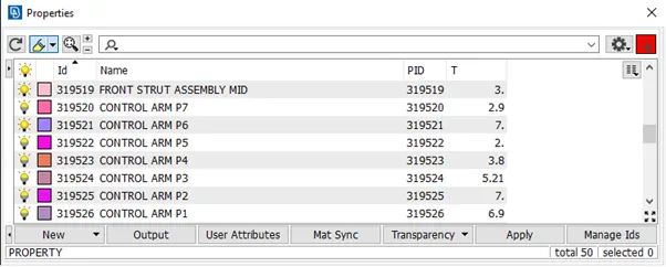
Set separate PID for each MID Surface since we have variable thickness to assign. The MID Surface extracted components are shown in the below Fig.
Thickness Assigned
Now the components are ready for Meshing.
MESH GENERATION AND QUALITY
To start with the MESHING process we have to set the given Quality Criteria. Here in this model we have Three Quality Criteria. One is for SHELL MESH using mixed elements and the other two for SOLID mesh using Tria Elements.
MESHING ON TYRE & RIM
To start with meshing, Set the given Quality Criteria in SOLIDS and feed in only Min. and Max. Length in SHELL.
Quality Criteria for Tria Elements (Tyre and Rim):
|
S.No |
Quality Criteria |
Value |
|
1 |
Target/Average length |
6.5 |
|
2 |
Minimum Length |
5 |
|
3 |
Maximum Length |
10 |
|
4 |
Skewness |
45 |
Common Quality Criteria for Tetra elements are:
|
S.No |
Quality Criteria |
Value |
|
1 |
Tet-collapse |
0.2 |
To do so, Press F11 in the Keyboard. A Quality Criteria - Presentation Parameter Pop-up appears. Set the above given values.
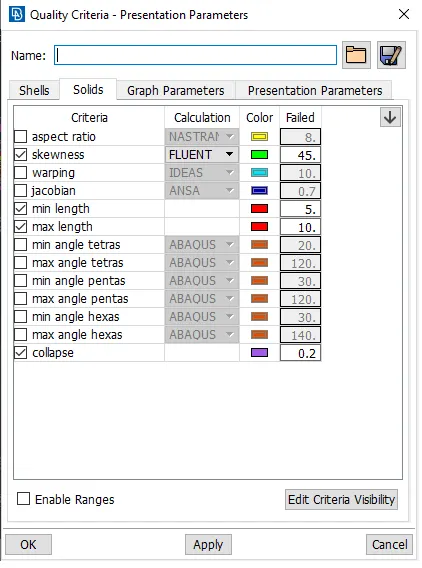
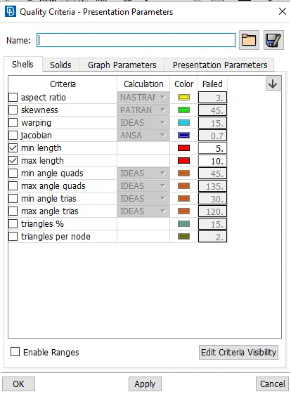
In the Presentation Parameters - Enable Elements % and and slide the Detail on demand effect slider to the (all details). Then hit APPLY then OK.
Next Open the MESH PARAMETERS in Utilities TAB. Then feed in the (Basic)
Mesh - GENERAL
Tria (Type)
Order of Mesh – 1ST ORDER
Then we have to add our Target length of the mesh flow as 6.5mm. And set the Min. Target Length as 5mm and Max Target Length as 10mm. Then hit ok.
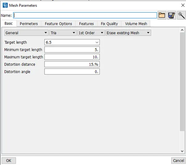
Now, we start with the Meshing process.
Go to MESH - Mesh Generation > Spot Mesh
The Spot Mesh algorithm gives better results than the free meshing method and creates the optimum number of shell elements, taking into account the element type already selected and the defined meshing parameters.
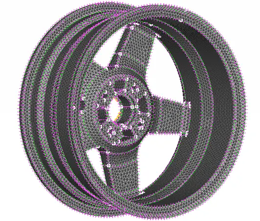
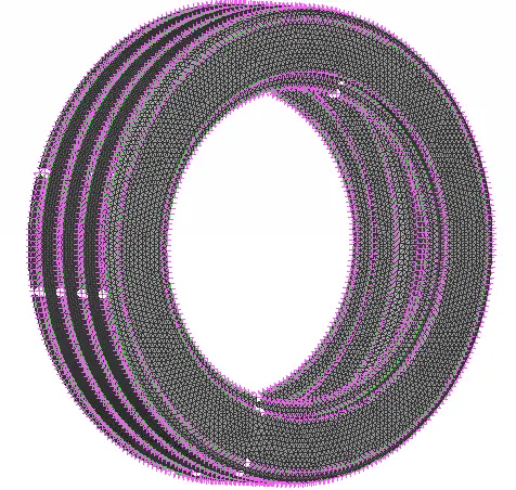
For Tyre and RIM I used Tria elements as per the given data. Started with the RIM. Go to PID > RIM > Show Only. Then start meshing with Mesh Generation > Spot Mesh (Mesh type Tria). After meshing the areas check the mesh for any Kinks and Dips. Reconstruct the area if any present. To do so Shell Mesh > Reconstruct will do the work. And also check for quality issues in Hidden mode (Drawing styles) simultaneously. Do the same for tyre too.
MESHING ON SUB COMPONENTS
Set the given Quality Criteria in SOLIDS and feed in only Min. and Max. Length in SHELL.
Quality criteria for Tria (For other components):
|
S.No |
Quality Criteria |
Value |
|
1 |
Target/Average length |
4 |
|
2 |
Minimum Length |
2 |
|
3 |
Maximum Length |
6 |
|
4 |
Skewness |
45 |
Common Quality Criteria for Tetra elements are:
|
S.No |
Quality Criteria |
Value |
|
1 |
Tet-collapse |
0.2 |
To do so, Press F11 in the Keyboard. A Quality Criteria - Presentation Parameter Pop-up appears. Set the above given values.
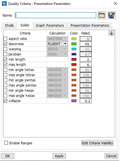
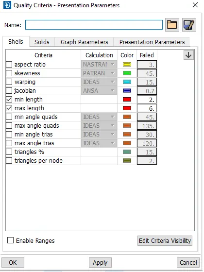
In the Presentation Parameters - Enable Elements % and and slide the Detail on demand effect slider to the (all details). Then hit APPLY then OK.
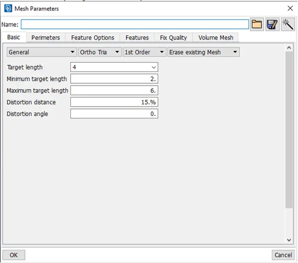
Next Open the MESH PARAMETERS in Utilities TAB. Then feed in the (Basic)
Mesh - GENERAL
Ortho Tria (Type)
Order of Mesh – 1ST ORDER
Then we have to add our Target length of the mesh flow as 4mm. And set the Min. Target Length as 2mm and Max Target Length as 6mm. Then hit ok.
Now, we start with the Meshing process for the sub SOLID components.
Go to MESH - Mesh Generation > Spot Mesh
The Spot Mesh algorithm gives better results than the free meshing method and creates the optimum number of shell elements, taking into account the element type already selected and the defined meshing parameters.
So we have to Mesh each part Individually. Keep in Shadow mode in Drawing Styles and start meshing. First we Mesh the curved surfaces and fillets with Mesh Generation > Spot Mesh (Mesh type Ortho Tria). After meshing the areas check the mesh for any Kinks and Dips. Reconstruct the area if any present. To do so Shell Mesh > Reconstruct will do the work. And also check for quality issues in Hidden mode (Drawing styles) simultaneously. Then on flat surfaces we change the Mesh type to (Tria) at Spot Mesh. Right click on unmeshed area shown in the user interface (work area) and click show only. Then window select the unmeshed areas and middle mouse click. Now Tria Mesh deployed on the Flat surfaces. Simultaneously do the same for all the parts.
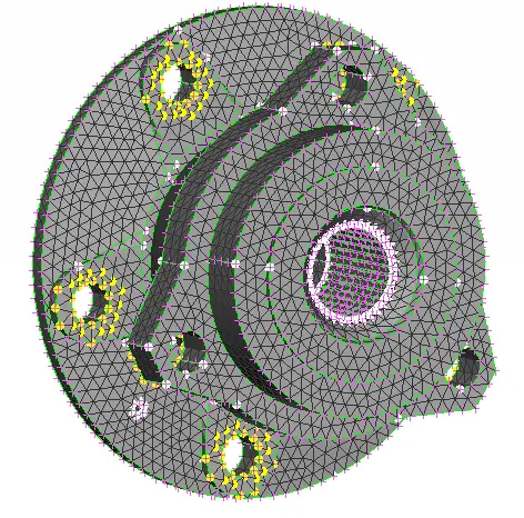
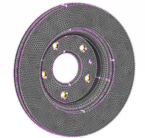
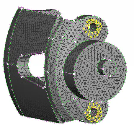
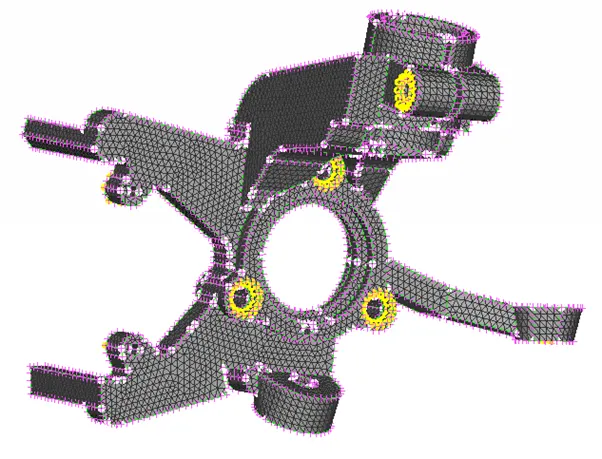
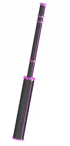
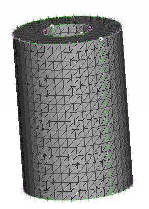
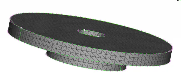
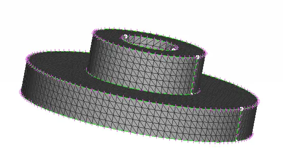
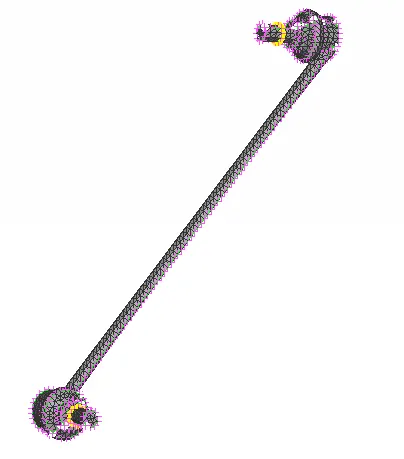
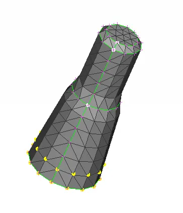
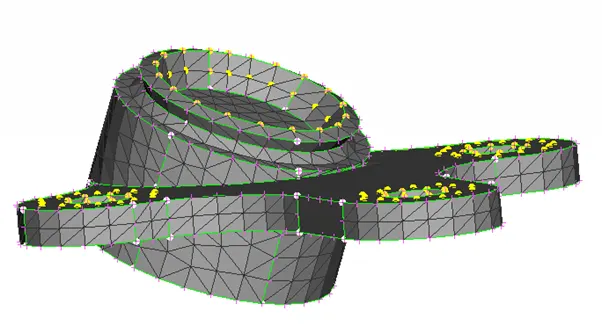
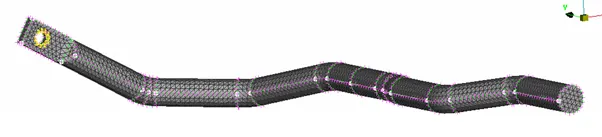
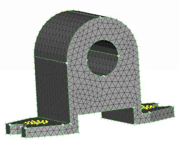
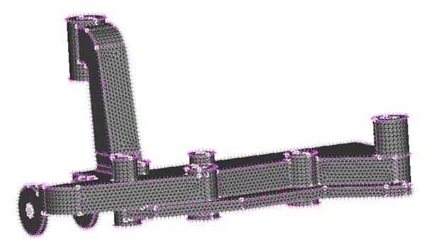
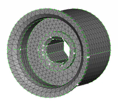
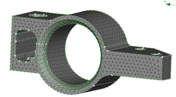
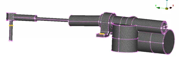
So now, we have the Mesh ready for Volume Mesh. Before that, we have the MID Surface to deploy SHELL MESH. So, let’s do it.
Set the given Quality Criteria
Quality criteria for Mixed elements (For Midsurface only):
|
S.No |
Quality Criteria |
Value |
|
1 |
Target/Average length |
4 |
|
2 |
Minimum Length |
2 |
|
3 |
Maximum Length |
6 |
|
4 |
Aspect |
3 |
|
5 |
Warpage |
15 |
|
6 |
Skewness |
45 |
|
7 |
Jacobian |
0.7 |
|
8 |
Minimum Quad Angle |
45 |
|
9 |
Maximum Quad Angle |
135 |
|
10 |
Minimum Tria Angle |
30 |
|
11 |
Maximum Tria Angle |
120 |
To do so, Press F11 in the Keyboard. A Quality Criteria - Presentation Parameter Pop-up appears. Set the above given values.
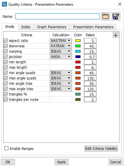
In the Presentation Parameters - Enable Elements % and and slide the Detail on demand effect slider to the (all details). Then hit APPLY then OK.
Next Open the MESH PARAMETERS in Utilities TAB. Then feed in the (Basic)
Mesh - GENERAL
Mixed Type – MIXED (Consist of Quad and Tria elements)
Order of Mesh – 1ST ORDER
Then we have to add our Target length of the mesh flow as 4mm. And set the Min. Length as 2mm and Max Length as 6mm. Then hit ok.
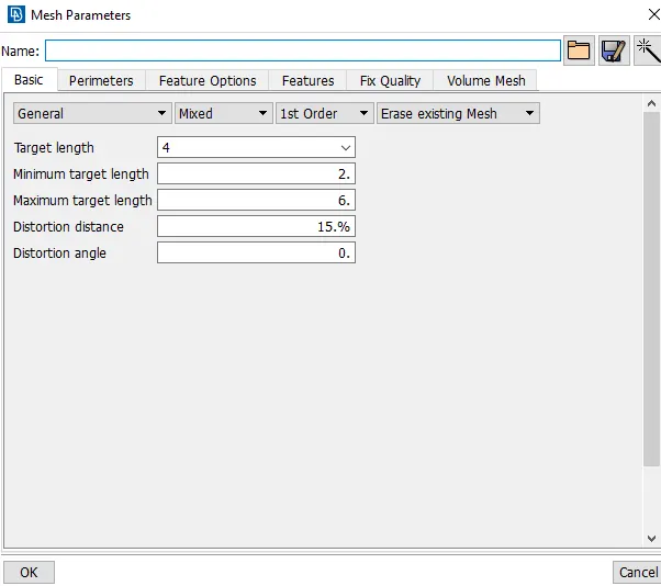
Now, we start with the Meshing process for the sub SOLID components.
Go to MESH - Mesh Generation > Spot Mesh
The Spot Mesh algorithm gives better results than the free meshing method and creates the optimum number of shell elements, taking into account the element type already selected and the defined meshing parameters.
We will have some Quality issues. To solve the Quality issues we have to use RECONSTRUCTION command from SHELL MESH module. RECONSTRUCTION creates high quality surface MESH and solves the quality failed areas with high quality mesh flow according to the Values set in Quality Criteria and Mesh Parameters. After a reconstruction SMOOTH command is used to refine the mesh construction. SMOOTH command uniforms the mesh generation without changing the mesh orientation. Some areas we have to use SPLIT and SWAP command from Elements module in order to eliminate, split/swap or move the Tria element. With SPLIT command The Tria elements can be eliminated and arranged with directional flow of the neighboring Tria elements. With SWAP command such as Opposite Trias, Back to back Trias are separated. The Trias can be either swapped to left or right direction of the Mesh flow. Even the SPLIT command help in solving Opposite Trias, Back to back Trias in some areas. I used PASTE command from Grids Module to rearrange/move a step back the falling Trias from the construction lines.
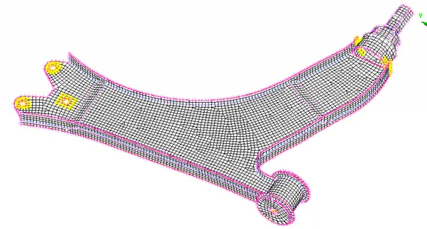
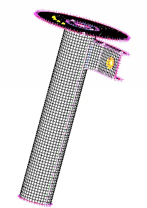
Now we have the SHELL MESH ready for FEA.
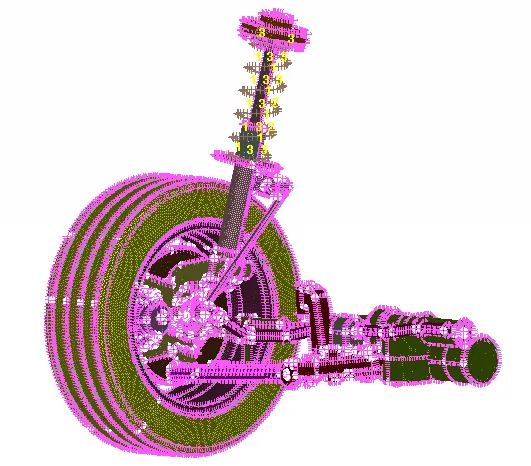
Complete FRONT SUSPENSION ASSEMBLY MESHED. Lets star with Volume Mesh for the SOLID COMPONENTS.
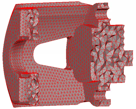
SOLID MESHING (TETRA MESH)
Solid Meshing is nothing but a Volume added with in the hollow space of a 3D Solid Part with Unstructured (Tetra Mesh). The Mesh is created based on the active Mesh which we performed before in Mesh generation.
There are two types of Solid Mesh.
- Tetra Mesh (Unstructured Mesh)
- Hexa Mesh (Structured Mesh)
In this challenge we are using TETRA MESH (Unstructured Mesh) for Solid Meshing.
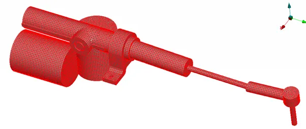
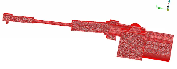
Before that we have to Define the volume. This function defines new Volume entities. To do so, Go to V.Mesh Module > Volumes > Define > Manual. A pop up appears and we have two options AUTO & MANUAL. Select MANUAL. Window select the FE Model Mesh or Meshed Macros. And middle mouse click. A PROPERTY HELP dialogue box appears. Here, Go to New > PSOLID. PSOLID dialogue box appears. Name the Psolid. The values are same. If provided we must change the PID & MID value. And hit OK. Now we have defined a PSOLID ID. Double click on it to Define as New Volume Entities. So now we can see that the FE Model Mesh is defined as a New Volume Entity. The FE Model Mesh will be highlighted.
Now we have to Mesh the Volume. To do so In V.Mesh > Volumes > List. A Volume popup appears. Select ID (We can see that the defined FE Model Mesh is highlighted) and Right mouse click. Then click on REMESH. A Volume Type popup appears. Mark the volume type as Tetra Rapid and Hit OK. The Volume is Meshed. REMESH - This command will mesh the Volume with the same Algorithm and the same Parameters that have been used the last time.
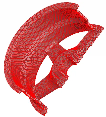
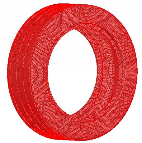
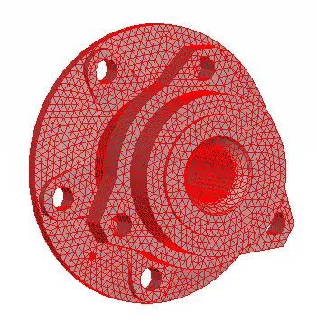
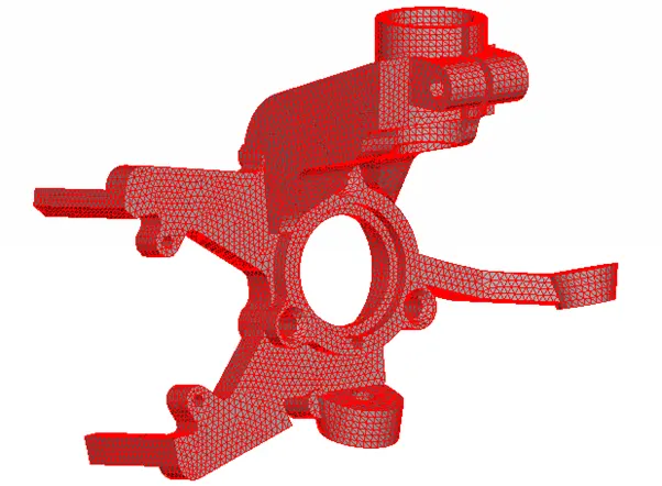
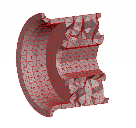
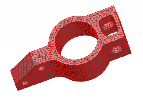
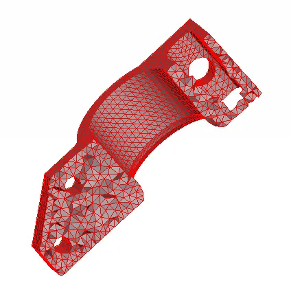
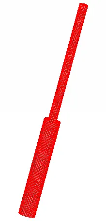
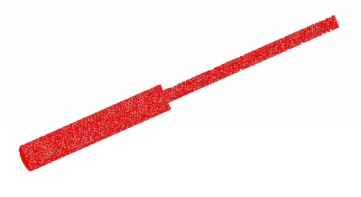
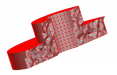
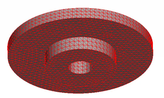
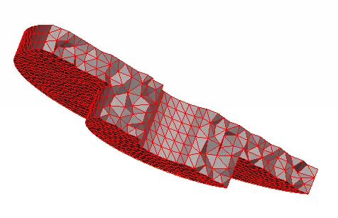
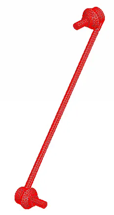
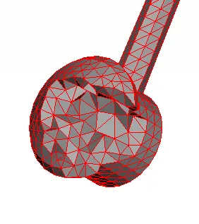
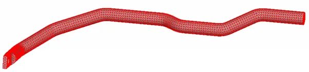
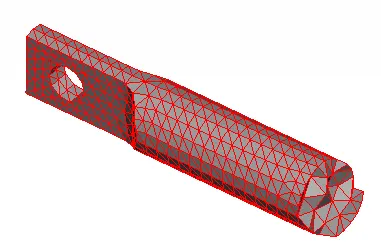
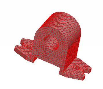
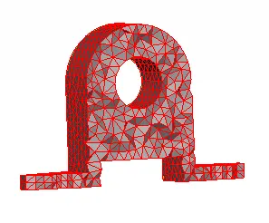
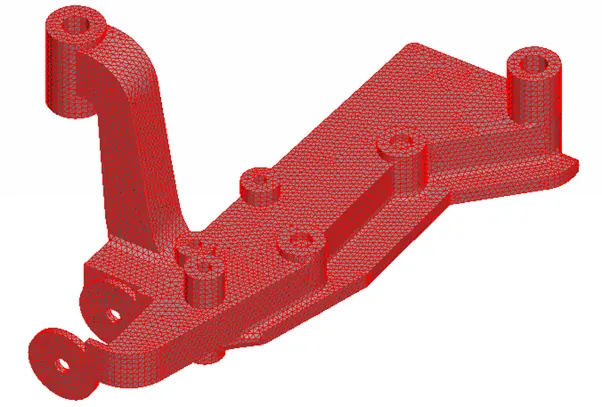
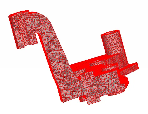
Similarly we have to define each FE Model Mesh individually and Mesh the Volume. The complete one is shown in the below Fig.
TETCOLAPSE SOLVED
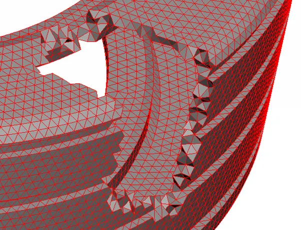
Few Tetcolapse issues were there. Those were fixed Manualy by V.Mesh > Improve > Move. This command can be used to move nodes. Selected nodes can be moved/slid freely in space with respect to global or a local coordinate system, on a geometrical or FE model surface, along a perimeter or can be offset from a perimeter.
DEFINED VOLUME
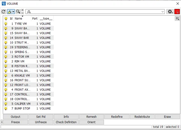
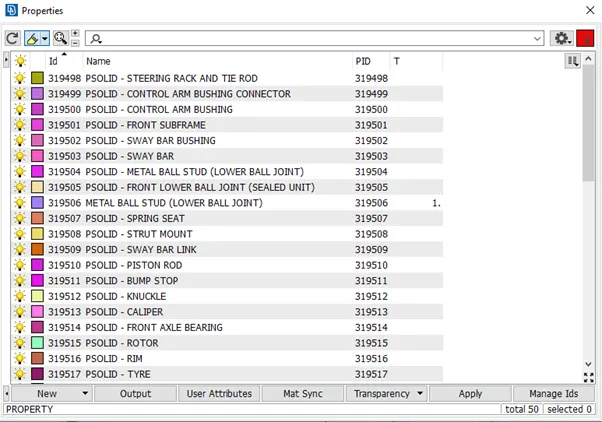
PSOLID ID
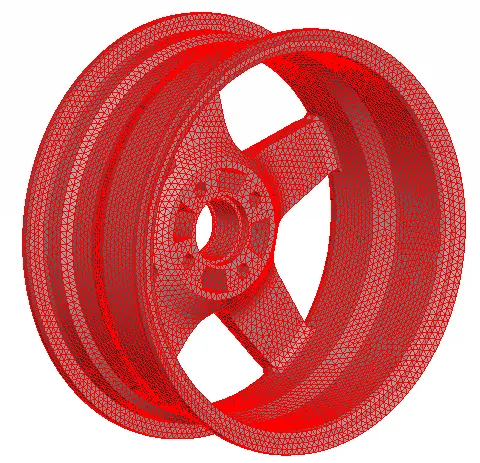
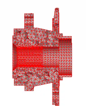
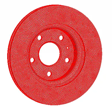
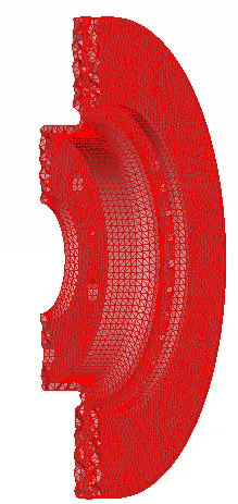
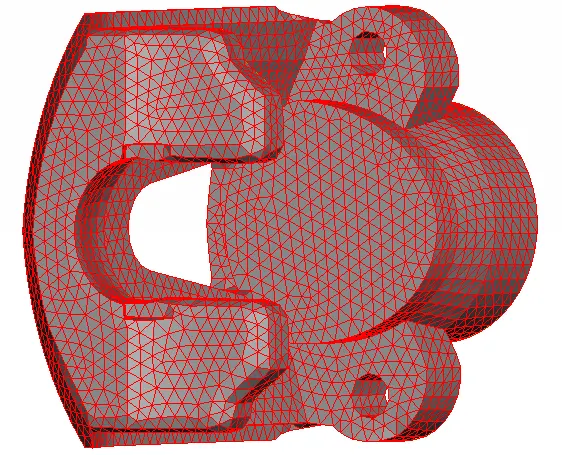
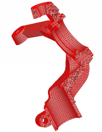
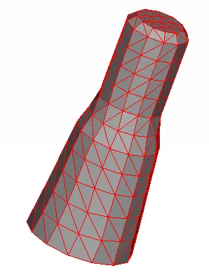
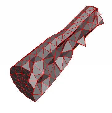
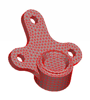
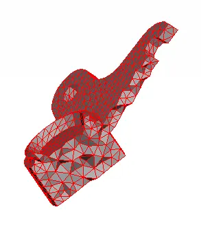
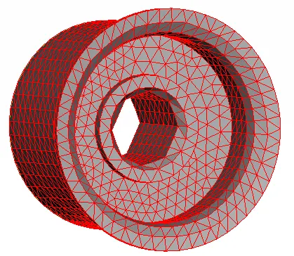
Solid Mesh Parts with cross sectional view.

CONNECTIONS
Connections are made on SOLID & SHELL Components.
NASTRAN SOLVER (DECK)
NASTRAN is a finite element analysis solver (Deck) for stress, vibration, buckling, structural failure, heat transfer, acoustics and aero elasticity analyses.
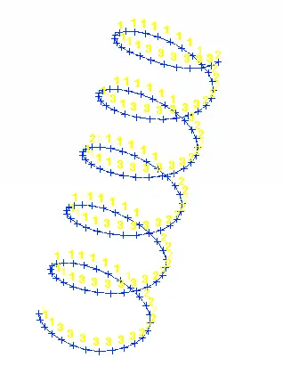
CBAR (1D ELEMENT) ON COIL SPRING
C BAR element is a 1 dimensional element which connects two grid points.
We use these type of connections on parts which has extentional stiffness and torsional stiffness along the neutral axis.
The Coil spring has both extentional and torsional stiffness. Since it has torsional rigidity and it is an elastic body which will have deformation with a single degree of freedom. So we use CBAR element to represent the Coil spring.
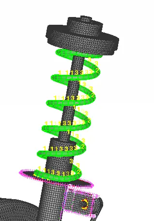
To do So. Go to NASTRAN > ELEMENTs > CBAR > Elements definition parameters pop-up appears. Pick the selection as Curve Box. Now select the curves created from the Coil spring. Feed in the diameter distance measured i.e ~9.98 in the INPUT Dialogue box and on confirmation Property help pop up appears. Create a new PBAR ID. Name it and in the Area press “SHIFT + ?” > Section parameters dialogue box appears. Set the Radius as 4.99 and hit OK. Again Hit OK on PBAR ID. Now we can see that the CBAR Element has created. If we measure the distance between the CBAR elements created. It’ll be the exact diameter distance we specified in the input pop-up. The representation is shown in the below Fig.
Now Press F11, QC > Presentation Parameters > Line Elements Cross-section > Draw Mode > as SOLID.
NUT AND BOLT CONNECTIONS:
In NUT and BOLT Connection, There are two connection methods.
- Automatic Connection using Connection Manager and
- Manual method by using RBE2 Connections.
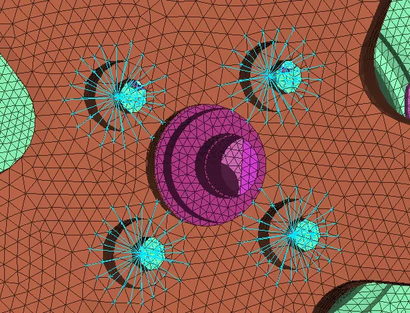
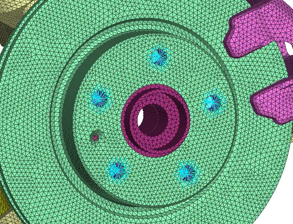
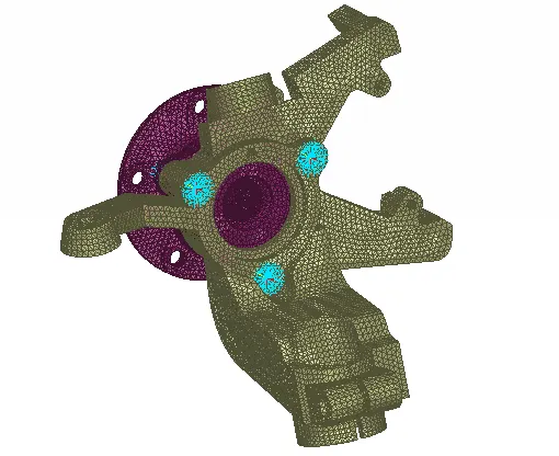
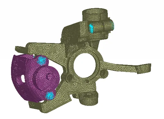
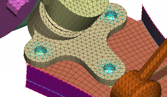
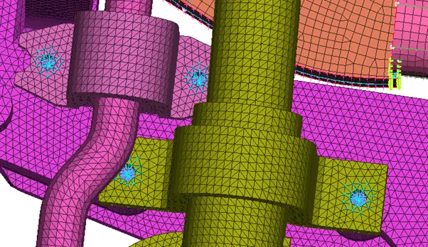
I used the manual RBE2 connection method. To do so, NASTRAN Deck Modules > ELEMENTS > RBE2 > Many node RBE2. “RBE2 Many nodes” pop up appears. We have to select the Slave Nodes and Master Nodes. Slave Nodes are (Dependent Nodes) and Master Nodes are Independent Nodes. Slave Nodes will behave depending on the Master Nodes. Now in FEATURE SELECTION Turn on LOOP command.
Here we have a NUT and BOLT Connections on
- RIM - ROTOR
- AXLE - ROTOR
- AXLE - KNUCKLE
- KNUCKLE - CALIPER
- BALL JOINT (SEALED UNIT) - CONTROL ARM
- SWAY BAR BUSHING, STEERING RACK BUSHING - SUBFRAME
The Nodes present on the Edge of the Perimeter Hole are the Slave Nodes. Select the Slave nodes as the Nodal Entity. Middle mouse click. It displays the number of nodes selected. Click next. On confirmation the Master node is created automatically based on the position of Slave Nodes. Again middle mouse click. Create Entity - popup appears. The connection created has a unique Element ID (EID), a Master ID (GN), No. of nodes. CM – Degree of Freedom. We have set the DOF as 123456. So the connection does not move. Hence it’s a rigid connection. In order to save the connection Create Entity > Part > Ask Always and click on Finnish. A MODEL BROWSER pop up appears. New > Part > Rename the Part ID and double click on the ID. Now the connection ID has been assigned. Now we have to do bolt connection between the Cluster. To Do so, NASTRAN Deck Modules > ELEMENTS > RBE2 > Two node RBE2. Select the two Master Nodes and middle mouse click. RBE2 (RBE2) Popup appears. Name it and set the CM (DOF) as 123456. The below Fig represents the NUT and BOLT Connections.
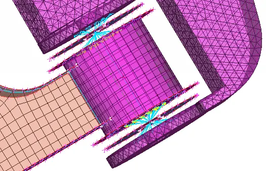
RBE2 CLUSTER CONNECTIONS:
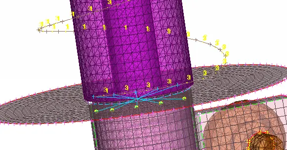
For RBE2 CLUSTER CONNECTIONS, I used the same manual RBE2 Command. To do so, NASTRAN Deck Modules > ELEMENTS > RBE2 > Many node RBE2. “RBE2 Many nodes” pop up appears. Now in FEATURE SELECTION click on the ++Nodes++ command. It’ll change to Entity selection. Now do element selection and middle mouse click, following the previous method will do the work. Here only the Command of selection and connection method varies. Here four nodes are selected in each element. The below Fig. represents the RBE2 CLUSTER Connection between the power window regulator and the Glass.
RBE2 CLUSTER Connections are made on
- COIL SPRING CBAR - STRUT & SPRING SEAT
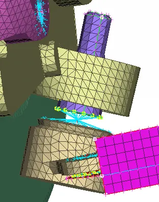
- BALL JOINT (STUD - SEALED UNIT) Since the data of ball bearing attached with the STUD was missing.
- CONTROL ARM BUSHING - SUB FRAME
This type of connection is alos called as RBE2 Spider. The connections are shown in the below Figs.
TWO NODE RBE2 SET CONNECTIONS
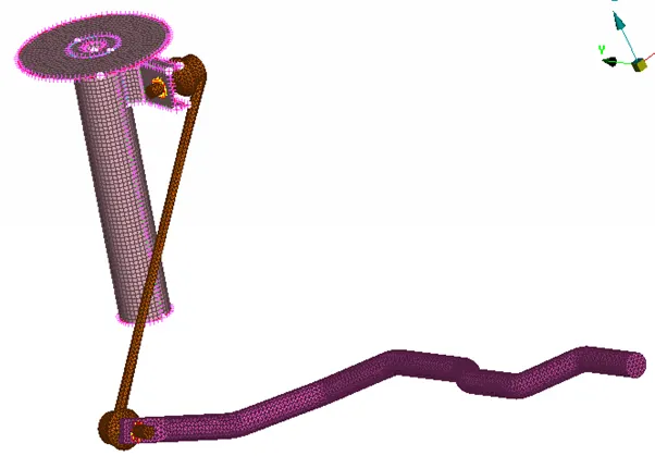
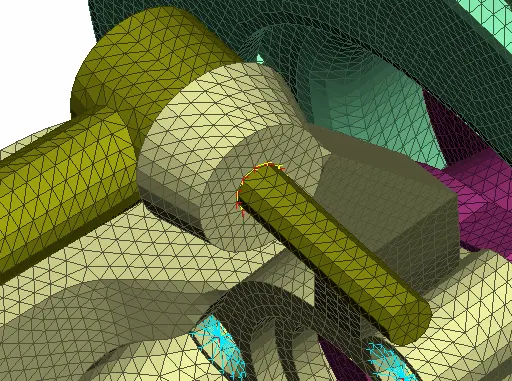
.Before that CONS > PROJECT were done on the areas where two node RBE2 SET connections are to be deployed. This is done for node matching. Now we start with TWO NODE RBE2 SET CONNECTIONS. To Do so, NASTRAN Deck Modules > ELEMENTS > RBE2 > Two node RBE2 > PICK as NODE SETS. Then select the nodes on the edge of the perimeter and the nodes matching on confirmation connections are deployed. This connections are given on
- STRUT CLAMP - SWAY BAR LINK
- SWAY BAR LINK - SWAY BAR
- TIE ROD – KNUCKLE
CONCLUSION
- Topology Operation already Done
- Geometry Cleanup & Surface cleanup is done
- MID Surface extracted for components which had a thickness of less than 5mm. Some Solid Components had thickness nearly satisfying to extract MID Surface was also considered for SHELL MESH
- Applied given Quality Criteria - Presentation Parameters and Meshing Parameters
- Mesh Generated
- QC and Mesh cleanup done
- Solid Meshing (Tetra Mesh) done
- Checked the model for Tetcolapse issues.
- Necessary connections has been realised & CBAR (1D Element) on Coil spring has been deployed.
Now the component is ready for NVH Simulation.