Roof challenge
AIM
To develop the essential flanges and reinforcements from the Given Roof styling and to provide appropriate dimensions. Roof ditch area the tool opening angle is only 3 degrees. And to do a curvature study on the roof and perform calculations to determine the position of the Bow-roof.
PROCEDURE
OUTER ROOF PANEL
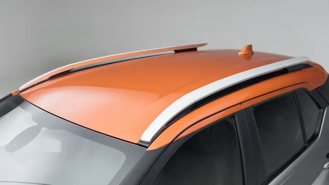
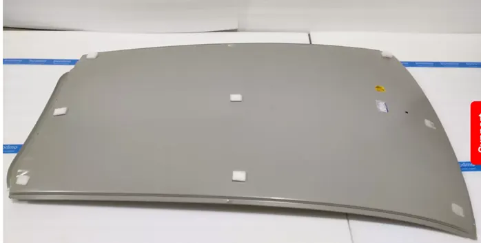
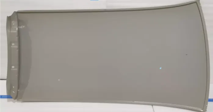
The roof panel is the section of material, usually sheet metal that forms the roof of a vehicle. The roof protects the vehicle occupants from sun, wind, rain, and other external elements. The roof is split into three sections - the aluminum roof panel, the strengthened C pillars, and the rear windshield.
OUTER PANNEL GIVEN SURFACE
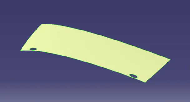
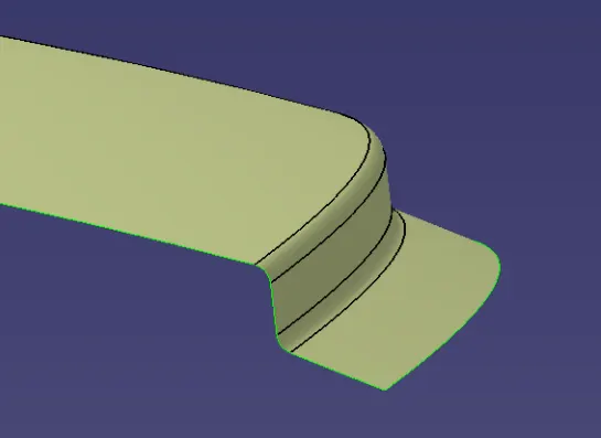
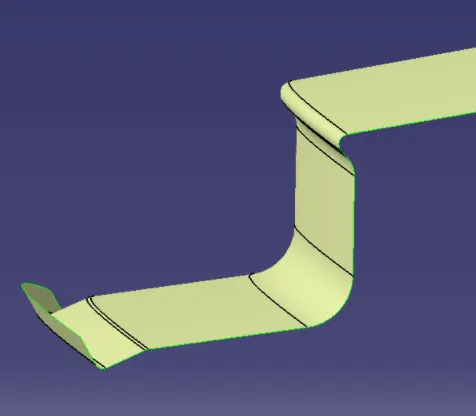
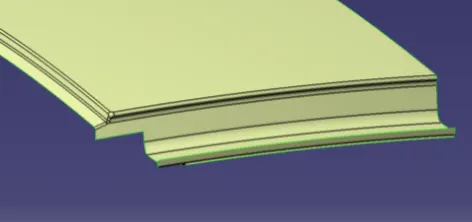
Both Outer front and rear Flanges are designed according to the mastersection.
OUTER ROOF PANEL FRONT FLANGE
OUTER ROOF PANEL REAR FLANGE
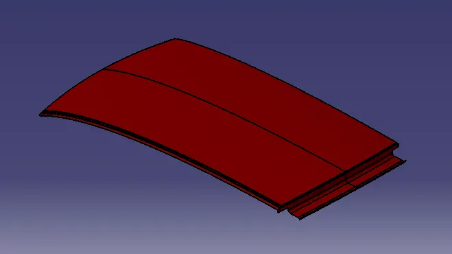
OUTER ROOF PANEL SOLID BODY
INNER ROOF RAILS
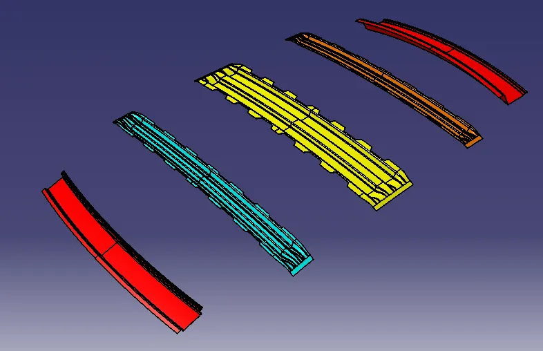
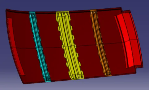
Inner Roof Rails consist of Front, Rear, Mid and Bow roof rails.
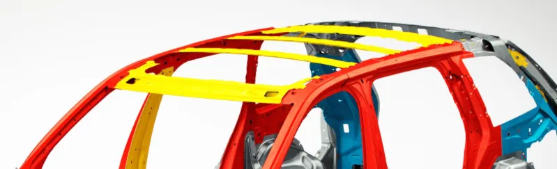
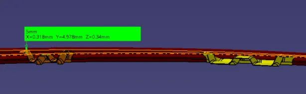
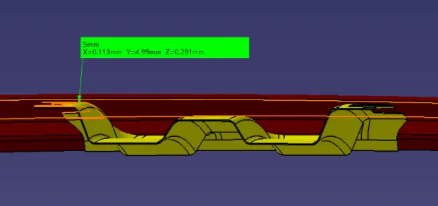
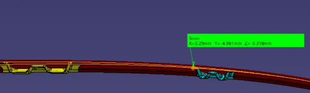
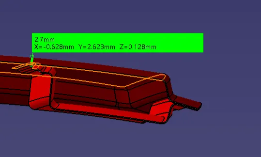
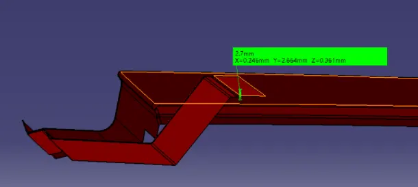
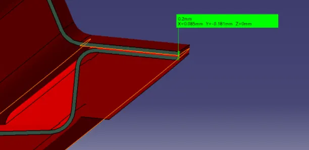
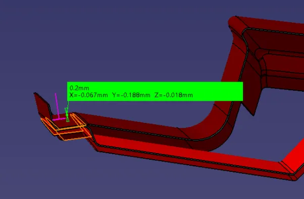
Inner Roof Rails are designed with the master section data provided. 5mm Gap between Roof rails Mastic points and outer panel is maintained. 2.7mm Gap is maintained between Front, Rear Roof rail and Outer panel where the mastics ooze out and fill the area. 0.2mm hemming Gap between outer panel and inner roof rail is maintained.
FRONT & REAR ROOF RAILS
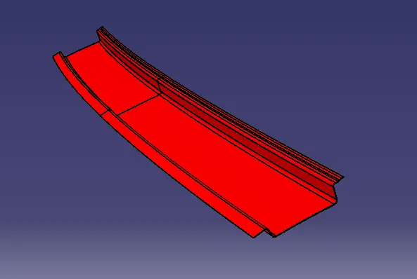
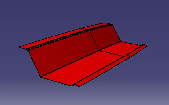
Front and rear ditch area part are provided with optimum angle for ensuring front and rear visibility criteria respectively and production criteria(positive draft angle) so that mounting of windshield and rear glass becomes easier. Front and rear roof rails are cut a part as there will be mounting of A and C pillars.
FRONT & REAR ROOF RAILS SURFACE
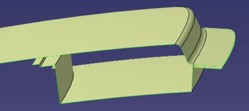
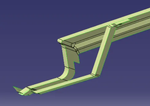
FRONT & REAR ROOF RAILS SOLID BODY
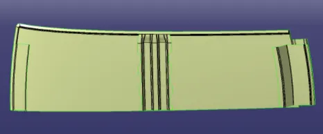
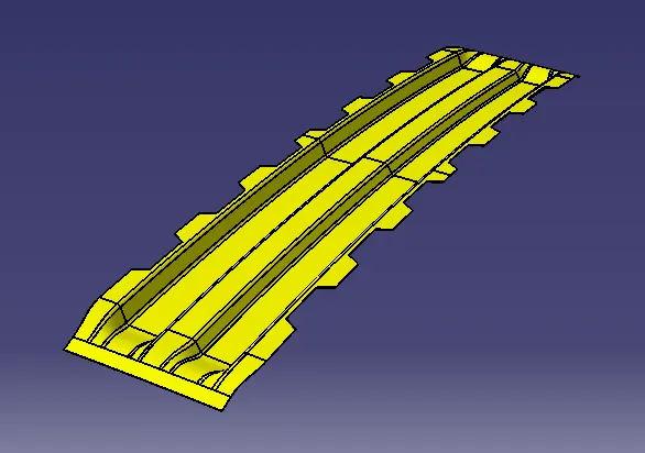
MID ROOF RAIL
Centre roof rail has two layers (with reinforcement), this is to strengthen the roof for roll over crash.
MID ROOF RAIL SURFACE

MID ROOF RAIL SOLID BODY
BOW ROOF RAILS 1 & 2
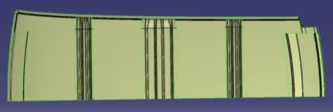
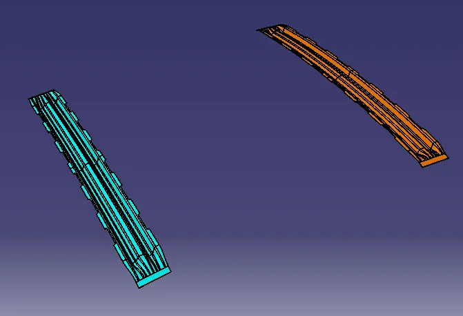
It consists of Front, Rear, Centre, Bow Roof I & II roof rails. Bow roof rails are provided for the support of roof surface and better protection of roof from crash. The bow roofs are provided with mastic sealant as they are assembled with the surface as welding is not possible, whereas the ditch area, front and rear area is welded with the roof.
BOW ROOF RAILS 1 & 2 SURFACE

BOW ROOF RAILS 1 & 2 SOLID BODY
HEAD LINER
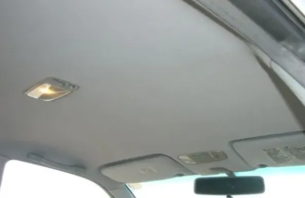
A headliner is the material that covers the ceiling of a vehicle, but it does more than hide bare metal with color-coordinated soft fabric. Headliners provide insulation against heat and noise, and they can also hide wiring and hardware for electrical components, antennas and other accessories.
ROOF ASSY. FINAL OUTPUT

ROOF CALCULATIONS
HEAT DISTORTION CRITERIA
It is the temperature at which the material starts softening when exposed to a fixed load at elevated temperature. Above this temperature the material can’t be used. In order to know whether the material is in safer zone according the positioning of bow roofs, the test is performed with the Formula
W = [1.73 x 10^(-3) x L] + [1.85 x 10^(-8) x (R^2)/t] + [ 1.10x10^(-3) x l] - 2.68
Judgement Condition : OK< 2.7> 3.1
Where
L = Roof Length in X-Direction[mm](Roof dimension in 0-Y)
R = Roof curvature
R = 2(Rx*Ry)/(Rx+Ry)
Rx = X curvature
Ry = Y curvature
t = Roof plate thickness [mm]
l = Bow Roof Span [mm]

Since the value is less than 2.7 it satisfies the Heat Distortion Criteria.
SNOW LOAD CRITERIA
Snow load is the downward force on a roof by the weight of accumulated snow and ice. The roof can fail if the snow load exceeds the weight
Qr = [Iy x t2] / [α x s x [(Rx + Ry)/2]2 x 10-8]
Where
α = My x Lx2 x 10-12 , My = Y(Ly-Y)
Judgement condition = Qr ≥ 3.1
250 ≤ s ≤ 380
t = Roof plate thickness [mm]
Ly = Distance between the front and rear roof Rails on the Vehicle along with 0Y[mm]
Length of Roof panel with the center point between Roof rail Front /Rear as the front and rear reference point.
Lx = Distance between the Left and Right end of the roof on the Roof BOW [mm]
Width of the roof panel exposed on the surface.
Y = Distance front Front Roof Rail to Roof BOW[mm]
s = Distance for which Roof BOW bears divided load [mm]
s = L1/2 + L2/2
Iy = Geometrical moment of inertia of Roof BOW (Y cross-section )[mm4]
Rx = Lateral direction curvature radius of roof panel Y cross-section on Roof BOW [mm]
Roof panel curvature Radius of the Length Lx in Front view
Ry = Longitudinal Direction curvature radius of the Roof panel X cross-section on Roof BOW [mm]
Roof panel X curvature radius of length s in Side view
MEASURING INERTIA To Find IY
Take an intersection between Mid and Bow roof rails individually. Fill the surface using fill command then Go to Measure Inertia and select Measure Inertia 2D from the popup then select the surface. Now we have got the value for the Moment of Inertia. M1 is the Minimum Principal Moment of Inertia and M2 is the Maximum Principal moment of Inertia.
BOW ROOF1 Moment of Inertia
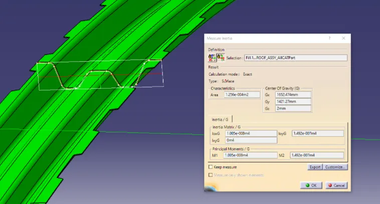
Conversion of m^4 to mm^4
M1 - 1.005 x 10^(-8) m(^4)
1.005 x 10^(-8) x (10^3)^4 mm^(4)
1.005 x 10^(4) mm^(4)
M2 – 1.492 x 10^(-7) m(^4)
7.004 x 10^(-7) x (10^3)^4 mm^(4)
7.004 x 10^(5) mm^(4)
Here we choose M1 - 1.005 x 10^(4) mm^(4) Min. Principal Moment of Inertia.
Moment of Inertia I = 1.005 x 10^(4) mm^(4)
BOW ROOF2 Moment of Inertia
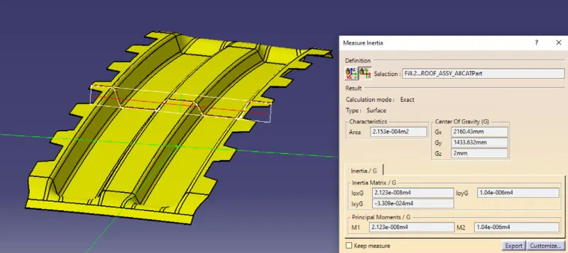
Conversion of m^4 to mm^4
M1 – 2.123 x 10^(-8) m(^4)
2.123 x 10^(-8) x (10^3)^4 mm^(4)
2.123 x 10^(4) mm^(4)
M2 – 1.04 x 10^(-6) m(^4)
1.04 x 10^(-6) x (10^3)^4 mm^(4)
1.04 x 10^(6) mm^(4)
Here we choose M1 - 2.123 x 10^(4) mm^(4) Min. Principal Moment of Inertia.
Moment of Inertia I = 2.123 x 10^(4) mm^(4)
BOW ROOF3 Moment of Inertia
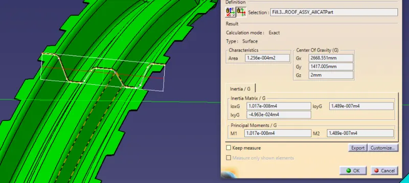
Conversion of m^4 to mm^4
M1 – 1.017 x 10^(-8) m(^4)
1.017 x 10^(-8) x (10^3)^4 mm^(4)
1.017 x 10^(4) mm^(4)
M2 – 1.489 x 10^(-7) m(^4)
1.489 x 10^(-7) x (10^3)^4 mm^(4)
1.489 x 10^(5) mm^(4)
Here we choose M1 - 1.017 x 10^(4) mm^(4) Min. Principal Moment of Inertia.
Moment of Inertia I = 1.017 x 10^(4) mm^(4)
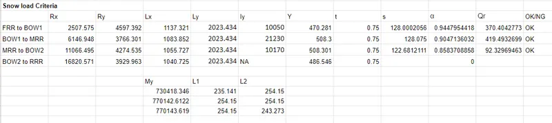
Both Qr and s Value satisfies the Snow load criteria.