Door Arm Rest Week 8 Challenge
AIM
To create Door Arm rest and add thickness to it.
PROCEDURE
Importing the geometry into the Part Workbench and multiple extract for the Door Arm Rest surface are done initially.
TOOLING AXIS CREATION
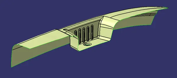
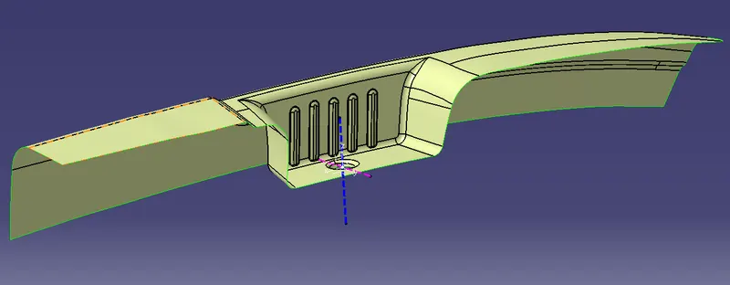
We have the Class A Surfaces provided for the Development of the Door Trim Panel. In order to create the tooling axis, first we have to create a point on the surface of the given Class A. Since we have a hole we use it to create a reference point with circle/sphere command. Then go to insert and add Axis system on the reference point created. Use intersection command and select the first element to intrsect as ZX plane and second element as Class A. We have the intrsection of ZX plane and Class A. Next select the line command and create two opposite reference lines with line type as point to point. Hide the intersection and use bisecting line command to create the Main Tooling Axis. Now we have a proper Tooling Axis for the given Class A.
DOOR ARM REST TOOLING AXIS
DRAFT ANALYSIS CLASS A SURFACE
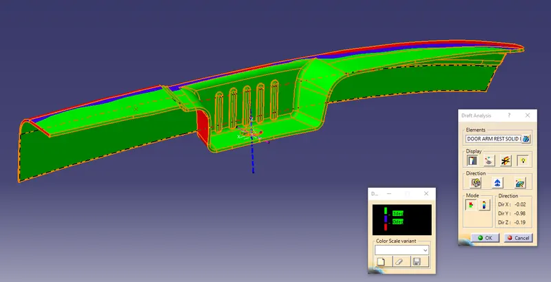
The Draft Analysis command allows us to detect if the part we drafted will be easily removed. This type of analysis is performed based on color ranges identifying zones on the analysed element where the deviation from the draft direction at any point, corresponds to specified values.
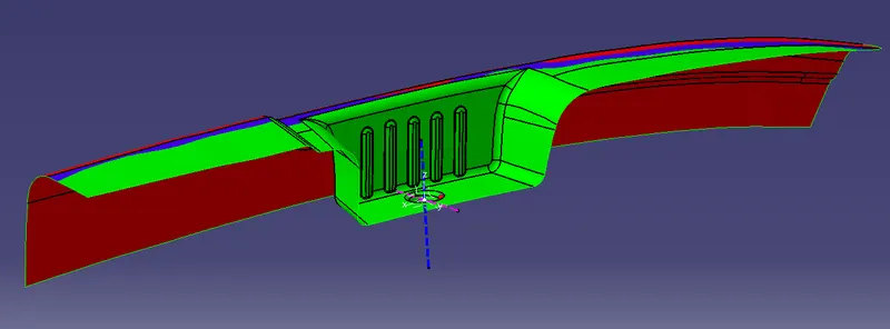
In order to perform the draft analysis in the given Class A, we use the Feature Draft Analysis. Command. Now a draft analysis Dialogue box appears. Here we have the color scale (Mode), Display and Draft direction. With this we can identify the maximum and minimum values for the analysis. Now click on the compass from Direction. Then grab the compass and place it on the Tooling Axis. Then Highlight the compass icon and then place it again according to the tooling direction. Set the maximum draft angle as 3deg and minimum as 0 in the Display Quick mode. Ensure the analysis colors are set in order Green, Blue and Red. Then lock the compass direction and click on the Class A Surface. Now we can see that the surface falls under the draft direction and hence the Tooling direction is accurate.
SIDE CORE DRAFT ANALYSIS
When there are inner and outer holes or undercuts on the plastic part that are different from the mold opening direction. Plastic parts cannot be ejection. The molded side hole or the undercut part must be made into a movable movable core. And the movable core is taken out before the plastic part is pushed out. Then take out the plastic parts. The mechanism for accomplishing these actions is called a side core pulling mechanism.
DOOR ARM REST DRAFT ANALYSIS CLASS A SURFACE
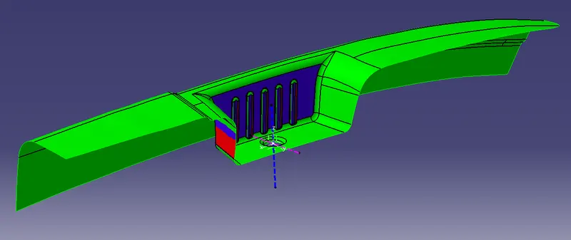
DRAFT ANALYSIS CLASS A SIDE CORE
CLASS B SURFACE
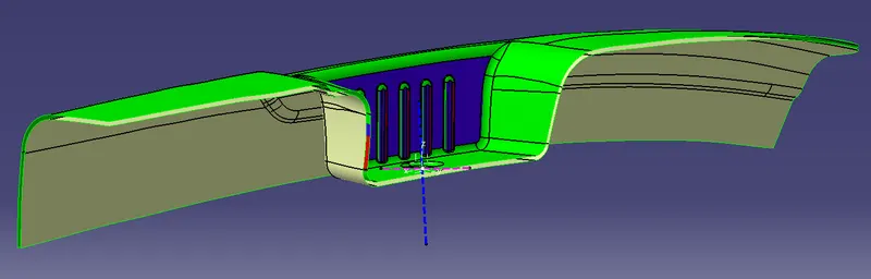
In order to create the Class B Surface offset Class A surface in reverse direction inwards to 2.5mm. We have the Class B ready, also used multi section to create missing faces during offset.
CLASS C SURFACE
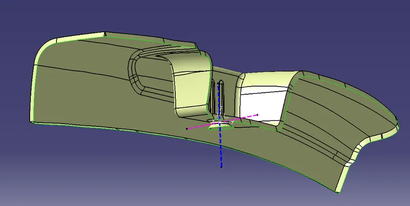
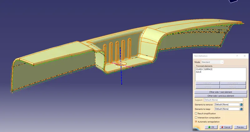
Class C Surface is created with respect to Class A. Here we create a boundary with the Class A. Now click on Sweep command. Sweep Dialogue box appears. Select the option 'with reference to Surface', select the guide curve and the reference surface. Then set the draft angle to 70deg inward/outward accordingly. Set the desired length and Hit OK. Join the C surface with A using Join command. Make sure all the surfaces intersect between CLASS A, B&C. Then perform Trim command to join the surfaces A, B and C. Do the same as well to the other surfaces.
DOOR ARM REST CLASS C SURFACE
DOOR ARM REST CLASS A,B&C CLOSED SURFACE
SOLID BODY
After Class A, B&C All the trims are converted into a Solid Body with Close Surface Command.
DOOR ARM REST SOLID BODY
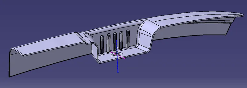
DRAFT ANALYSIS DOOR ARM REST SOLID BODY
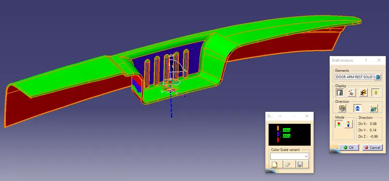
DRAFT ANALYSIS SOLID BODY SIDE CORE