Week 2- 2R Robotic Arm Challenge
AIM
To simulate the forward kinematics of a 2R Robotic Arm using MATLAB.
PROCEDURE
Here we are writing a program to simulate the forward kinematics of a 2R Robotic Arm.
Things to remember
A 2R Robotic Arm consist of two LINKS, two rotational joints and a Manipulator.
So we have to find the final position of a 2R Robotic Arm.
To do so
- We have to calculate the position of LINK 1 and LINK 2.
Link 1 has an angle of 'theta1' with respect to x-axis and Link 2 has an angle of 'theta2' with respect to x-axis. The length of Link 1 is 'l1' and the length of LINK 2 is 'l2'. The starting point is connected to the base of the robot and the ednding point is connected to Link 2. The co-ordinate of the starting point is (0,0) and the co-ordinate of the end point of the first link is (lcostheta,lsintheta).
Now the end point of Link 1 is the starting point of Link 2 and end point will be the manipulator. Let us assign a co-ordinate for the starting point of the Link 2 as (x1,y1) and assing a co-ordinate for the end point of the manipulator as (x2,y2).
Here
x2 = x1 + l2*cosd(theta2) and y2 = y1 + l2*sind(theta2)
So, now we have three co-ordinates to calculate the movement of the 2R Robotic Arm which is [x0,y0],[x1,y1],[x2,y2].
Now, let us start writing the program. Under Editor > Open a new script window > First we start with the basic flow and then we feed in the Input values of 'l1' of first length as 1m and 'l2' of second length as 0.5m. 'theta1' is set as angle 45 degree, 'theta2' is set as angle 30 degree.
Next we feed in the Cordinates. 'x0' and 'y0' is set as 0 because, It is the starting point of Link 1 which is the base of the robot in a fixed state. 'x1' set as l1*cosd(theta1), 'y1' set as l1*sind(theta1).
Now we determine the end point of Link 2. x2 set as 'x1' + l2*cosd(theta2) and 'y2' set as y1 + l2*sind(theta2). Then run the command by hitting 'CTRL' + 'ENTER'.
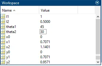
We can see that the values has been executed in the 'Workspace'. It is shown in the below Fig.
WORKSPACE WINDOW
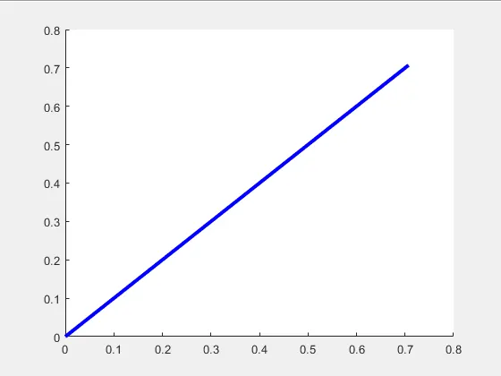
Next we have to make plot to visualize the Links with three co-ordinate values. Feed in %Plotting and starting with line command, First we have to provide the x co-ordinates of the two points to deploy line from the origin which is [x0 x1] and the y co-ordinates which is [y0 y1] and set the 'linewidth' parameter with a thickness of 3. Then type 'color','b' to color the line with blue. Now run the program and we get a line graph in blue color which represents LINK 1 as shown in the below Fig.
PLOT GRAPH - LINK 1
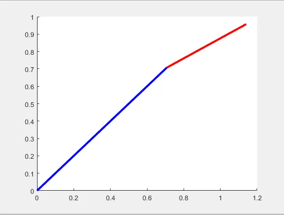
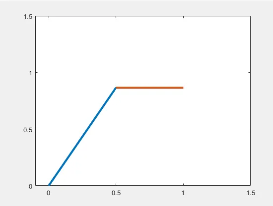
Now for Link 2 we set the co-ordinates of 'x' as [x1 x2] and the co-ordinates of 'y' as [y1 y2] and set the 'linewidth' parameter with a thickness of 3. Then type 'color','r' to color the line with red. Now run the program and we get the representation of line graph i.e LINK 1 (Blue) in color which is 1m and LINK 2 (Red) in color which is 0.5m as shown in the below Fig.
PLOT GRAPH - LINK 1 & 2
SCRIPT WINDOW
% Forward kinematics of a 2R robotic arm
clear all
close all
clc

% Inputs
l1 =1;
l2 = 0.5;

theta1 = 45;
theta2 = 30;

% Cordinates
x0 = 0;
y0 = 0;

x1 = l1*cosd(theta1);
y1 = l1*sind(theta1);

x2 = x1 + l2*cosd(theta2);
y2 = y1 + l2*sind(theta2);

%Plotting
line([x0 x1],[y0 y1],'linewidth',3,'color','b')
line([x1 x2],[y1 y2],'linewidth',3,'color','r')
ANIMATION PROCESS OF 2R ROBOTIC ARM using FOR LOOP
Now we have the line graph. And inorder to move the arm of Link 2 to we have to manually change the values of theta to 0,30,95 respectively.
Here,
We have multiple values of theta1 and theta2. For each value of theta1 and theta2 we are going to create a plot. And by combining all the plots together we create the animation of the 2R Robotic Arm.
To do so,
Under Editor > Open a new script window > First we start with the basic flow and then we feed in the Input values of 'l1' of first length as 1m and 'l2' of second length as 0.5m.
Here for 'theta1' and 'theta2' will be an array. And we use 'linspace' command.
['linspace' Generate linearly spaced vector.
For example
y = linspace(x1,x2) returns a row vector of 100 evenly spaced points between x1 and x2.
y = linspace(x1,x2,n) generates n points. The spacing between the points is (x2-x1)/(n-1).
linspace is similar to the colon operator, “:”, but gives direct control over the number of points and always includes the endpoints. “lin” in the name “linspace” refers to generating linearly spaced values as opposed to the sibling function logspace, which generates logarithmically spaced values.]
So, 'theta1' is set as linspace(0,90,10) and 'theta2' is set as linspace(0,90,10). so 'theta1' and 'theta2' has multiple values. so inorder to change the values of theta frequently we need to program it. To do that we have to use the 'for loop' command.
Write in 'for' i = 1:length(theta1). Here, length(theta1) refers to the values of 'theta1'. So the values are going to change from 1 to 10. Each time the value changes, It will execute the set of commands present inside the 'for loop'. Now write THETA1 = theta1(i) ['THETA1' is a 'variable' which has single value] here, we need to use the loop counter variable 'i' to access the particular value. In order to have a movement the 'Link 2' depends on 'Link 1'. To do so, we set another 'for loop' for 'theta2'. Write 'for' j = 1:length(theta2) and we write THETA2 = theta2(j). We have to make sure that the 'loop counter variable' is different for each 'for loop'. For each value of 'theta1' we are looping through the value of 'theta2'. So inorder to perform forward kinematics, we have to feed in the values of the co-ordinates.
'x0' and 'y0' is set as 0 because, It is the starting point of Link 1 which is the base of the robot in a fixed state. 'x1' set as l1*cosd(THETA1), 'y1' set as l1*sind(THETA1).
Now we determine the end point of Link 2. x2 set as 'x1' + l2*cosd(THETA2) and 'y2' set as y1 + l2*sind(THETA2). Here we replaced the 'theta1&2' with the variable 'THETA1' AND 'THETA2'.
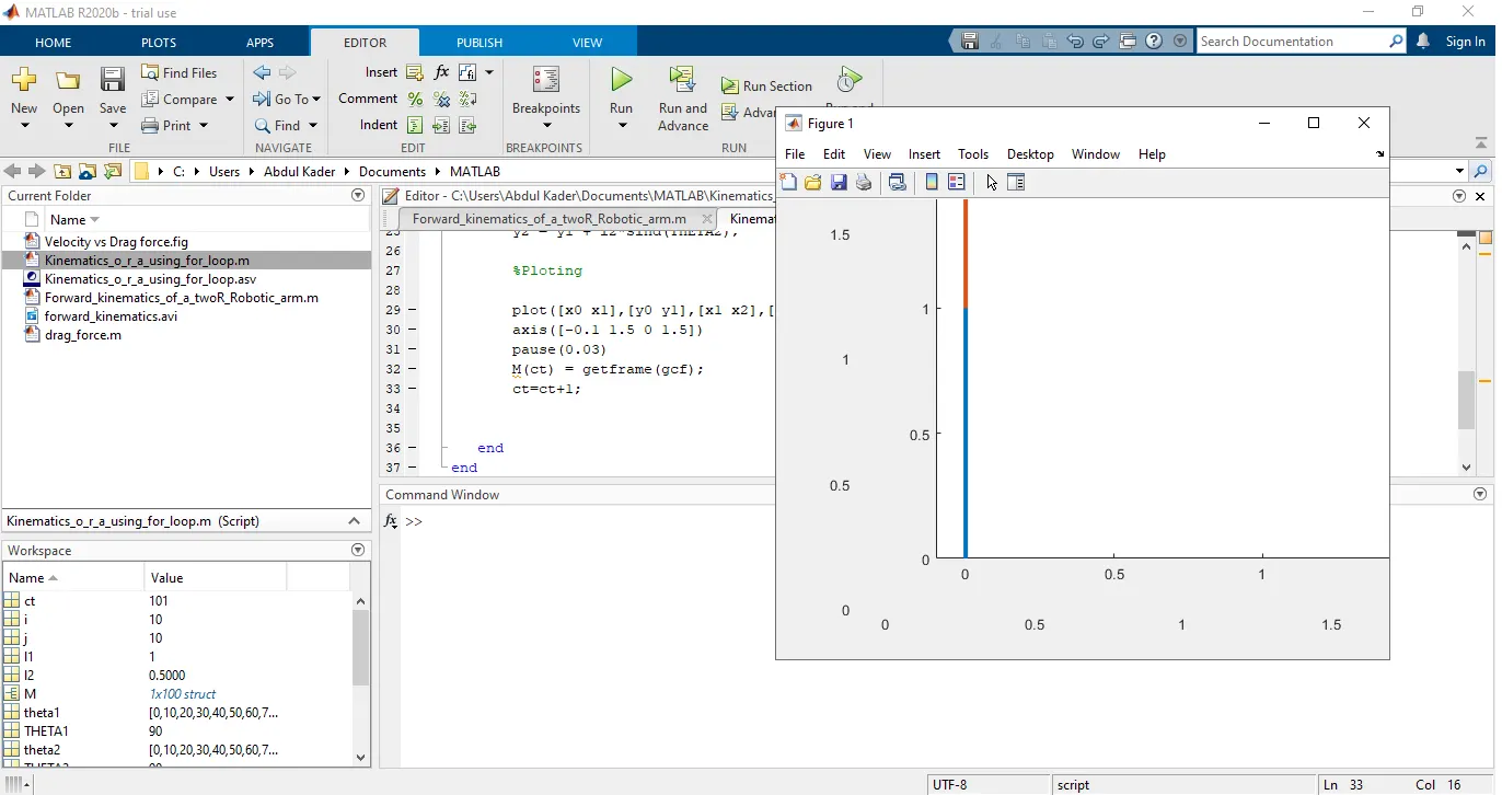
Feed in a single 'plot' statement as [x0 x1],[y0 y1],[x1 x2] and set the 'linewidth' parameter with a thickness of 3. Then we have to fix the 'axis' where we are changing our x-limits from '-0.1 to 1.5' and y-limits from '0 to 1.5'. And we add the 'pause' command with (0.03) so that it will 'pass the code' between every movement of the arm. In order to make it as a movie in frames > we use an array called 'M'. i.e M(ct) = getframe(gcf). so by using 'getframe' we get a particular figure window and save it in an array called 'M'. And each time 'for loop' is excecuted we increment it with counter ct = ct + 1. Also add 'ct=1' before 'for loop' command. And end with two 'end' commands. Now at the end of the 'end' command we write in as movie(M) where MATLAB will generate a movie with all the frames.
In order to save the frame as a video file in AVI format we write a command as videofile = VideoWriter('forward_kinematics.avi','Uncompressed AVI') so we have given the filename along with a format. After this we have to set a 'open' command 'open(videofile)'. Then 'writeVideo(videofile,M)' we say it to write the videofile with the frames we have. And finally we set it as 'close(videofile)'. So now, When we run the program we can see that a video file has been saved in our current folder. And also the plot graph animation playing as shown in the below Fig.
PLOT GRAPH ANIMATION
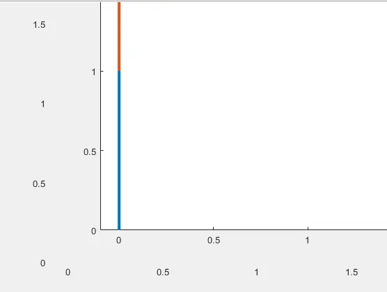
That is how we create an animation and save it as a movie i.e a video file in AVI format. The created video is embedded at the end of the page.
SCRIPT WINDOW
clear all
close all
clc


%Inputs
l1 = 1;
l2 = 0.5;
theta1 = linspace(0,90,10);
theta2 = linspace(0,90,10);

ct=1;
for i = 1:length(theta1)
   THETA1 = theta1(i);
   for j = 1:length(theta2)
       THETA2 = theta2(j);
       x0 = 0;
       y0 = 0;

       x1 = l1*cosd(THETA1);
       y1 = l1*sind(THETA1);


       x2 = x1 + l2*cosd(THETA2);
       y2 = y1 + l2*sind(THETA2);

       %Ploting

       plot([x0 x1],[y0 y1],[x1 x2],[y1 y2],'linewidth',3)
       axis([-0.1 1.5 0 1.5])
       pause(0.03)
       M(ct) = getframe(gcf);
       ct=ct+1;


   end
end

movie(M)
videofile = VideoWriter('forward_kinematics.avi','Uncompressed AVI');
open(videofile)
writeVideo(videofile,M)
close(videofile)
Animated Video of the 2R Robotic Arm
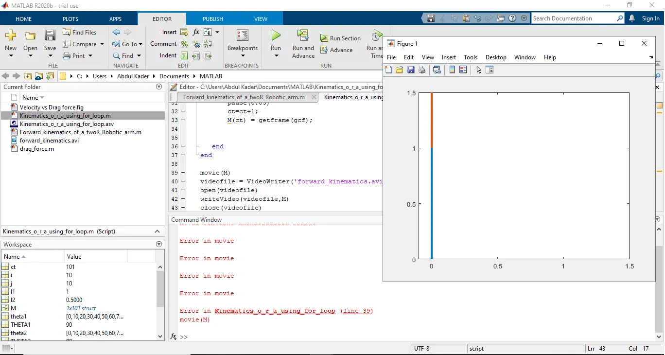
ERROR
The reason behind the error is frames are set after the counter command. So when we set the frames after pause command and set the counter command after frames command the problem get solved.
After