Week 8 - Challenge 4 - Coin Holder Design
AIM
Create the Coin Holder Plastic component through the given Class-A surface. To begin with, the tooling axis for the given Class-A Surface should be created meeting the requirements of the draft angle and at the end perform the Draft analysis on the model.
Take the Thickness of the component to be 2.5 mm
- Import CAD file.
- Class A Surface
- Class B Surface
- Class C Surface
- Tooling Axis
- Publication
- Free Form Analysis
PROCEDURE
- Import the given CENTER CONSOLE COIN HOLDER - IGS file into CATIA V5 and Save it as .CATPart
CLASS A SURFACE
The Class A Surface of the CENTER CONSOLE COIN HOLDER is defined in the Geometrical Set. 1. Here we can see that the surfaces of the given CLASS A SURFACE is not topologically connected. In order to do that, select the Geometrical Set. 1 and perform a Join operation. To ensure that the CLASS A is joined do a boundary to verify we gave a closed geometry.
CLASS B SURFACE
Insert a separate Geo.set and Extract the flat surfaces of the Class A except the edge fillet region into three sections using extract command as shown in the image.
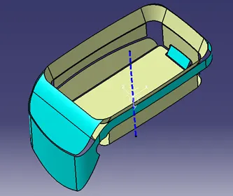
Do an offset of 2.5mm for the extracted surfaces. After offset use untrim command to reshape the extracted surface. After untrim process use trim command to join the surfaces individually. After achieving the final component do apply fillets as per the class A. fillet values must not be same as class A. Since we did an offset of 2.5, the fillet values must be subtracted with the offset value to get the desired values.
CLASS C SURFACE
To form a Class C Surface we need Class A and B which we have it ready now. Here the Class A has a whole at the side. To get it done we have to use boundary command to extract the lines of it. Then use the Sweep command and select the Guide curve as the Class A holes boundary and reference as to the surface of Class A, length as 10mm, angle set to 90 degree and hit OK. Now we have Class C surface for the hole area. Leave it a side and then with the Class B surface create a boundary. Use Sweep again and select the Class B boundary as a guide curve and reference as to the surface of Class B, length as 13mm, angle set to 90 degree and hit OK. We have two Class C one is for the hole and the other is to join Class A and B. First Join the Class C with the respected surfaces and perform a trim command to get the desired component.
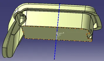
SOLID BODY
Insert a body and name it as Solid Body. Before creating a Solid body with CLASS A, B,C ensure the geometry is closed using Boundary. Now set in Part Body and by using Close Body command select the final component to close and hit OK. We have a Solid Body now.
TOOLING AXIS
In order to create a Tooling Axis first we have to analyze the given Geometry. The Tooling direction we create determines the clearance on all the faces of the geometry. So that there won’t be any issue while ejecting the part from Core and Cavity. By analyzing the geometry we know that the clearance of tooling direction is on the Z Axis. Here in this scenario we create a Dummy Tooling Axis with reference to the point. And to verify the Tooling Direction we need to perform a Draft Analysis. If we have the Tooling direction cleared the rename the dummy as Tooling Axis.
PUBLICATION
Publication acts as a reference to the geometry. So before Draft Analysis we have to publish both the CLASS A and Tooling Axis.
FREE FORM ANALYSIS
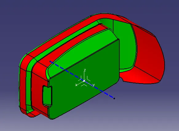
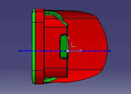
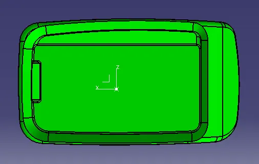
Free form Analysis is done to ensure the part we drafted is easily removed from the Core and Cavity. In order to do that Go to Insert > Analysis > Feature Draft Analysis. Now Draft Analysis popup appears. There in direction section select the compass to define the draft direction. Drag the compass and place it on the Tooling Axis direction, then lock the draft direction. Now select on the Class A Surface which shows the positive and the negative angles in two different colors. Green is Positive angle and Blue represents the negative angle. With 3 degree set in positive angle and -0.1 in the negative angle we have the tooling axis direction clearing the draft analysis. So the Tooling axis is the proper direction.
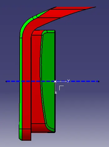
DRAFT ANALYSIS REPORT – CLASS A SURFACE
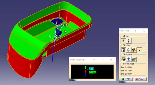
DRAFT ANGLE IN VARIOUS ORIENTATIONS
ISOMETRIC VIEW
FRONT VIEW
RIGHT SIDE VIEW
TOP VIEW