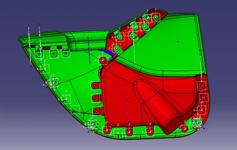
Week 11 - Final project
AIM
To prepare the part with given Class A following the master section with all the engineering features.
- Importing the geometry into the Product Assembly Workbench and multiple extract the surface for all the trims are done initially.
PROCEDURE
TOOLING AXIS CREATION
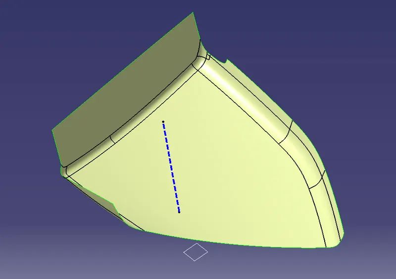
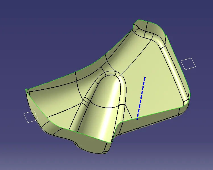
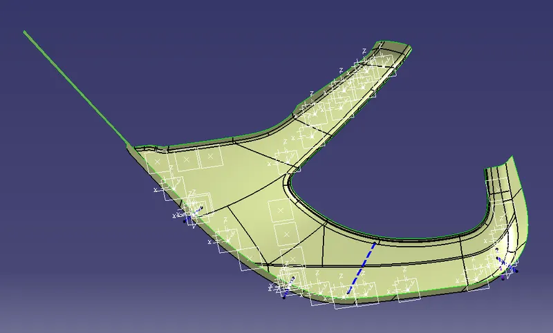
We have the Class A Surfaces provided for the Development of the Door Trim Panel. In order to create the tooling axis, first we have to create a point on the surface of the given Class A. Then we have to create a Plane in zx direction with the reference point. Here we don't have the necessity to use the intersection command to create a Tooling Axis. Since the given surface does not have any complex shapes we create a Plane with reference to the Point created on the surface of the Axis system. Now we have our proper Tooling Axis for the given Class A. Similarly we do the same for other Trims.
MAPOCKET 1
MAPOCKET 2
LOWER SUBSTRATE
ARM REST
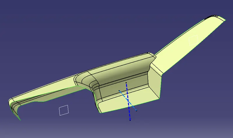
DRAFT ANALYSIS CLASS A SURFACE
The Draft Analysis command allows us to detect if the part we drafted will be easily removed. This type of analysis is performed based on color ranges identifying zones on the analysed element where the deviation from the draft direction at any point, corresponds to specified values.
In order to perform the draft analysis in the given Class A, we use the Feature Draft Analysis. Command. Now a draft analysis Dialogue box appears. Here we have the color scale (Mode), Display and Draft direction. With this we can identify the maximum and minimum values for the analysis. Now click on the compass from Direction. Then grab the compass and place it on the Tooling Axis. Then Highlight the compass icon and then place it again according to the tooling direction. Set the maximum draft angle as 3deg and minimum as 0 in the Display Quick mode. Ensure the analysis colors are set in order Green, Blue and Red. Then lock the compass direction and click on the Class A Surface. Now we can see that the surface falls under the draft direction and hence the Tooling direction is accurate.
SIDE CORE DRAFT ANALYSIS
When there are inner and outer holes or undercuts on the plastic part that are different from the mold opening direction. Plastic parts cannot be ejection. The molded side hole or the undercut part must be made into a movable movable core. And the movable core is taken out before the plastic part is pushed out. Then take out the plastic parts. The mechanism for accomplishing these actions is called a side core pulling mechanism.
DRAFT ANALYSIS CLASS A SURFACE – MAP POCKET 1
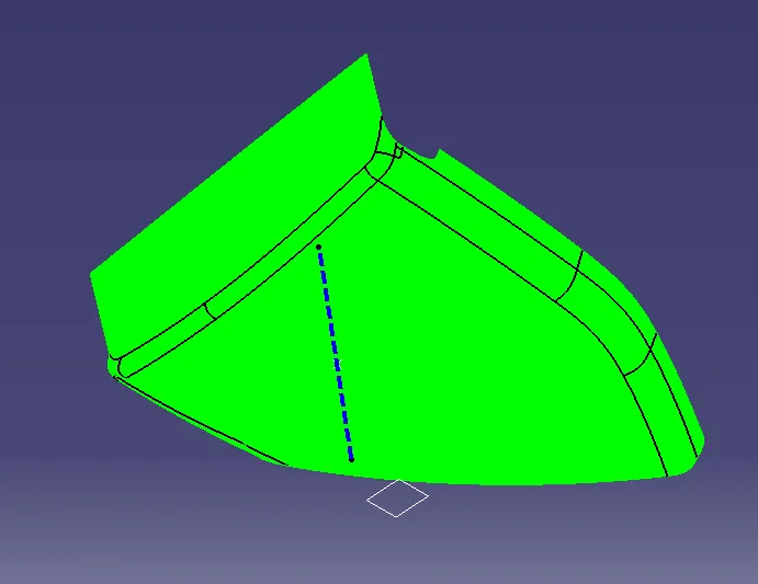
DRAFT ANALYSIS CLASS A SURFACE – MAP POCKET 2
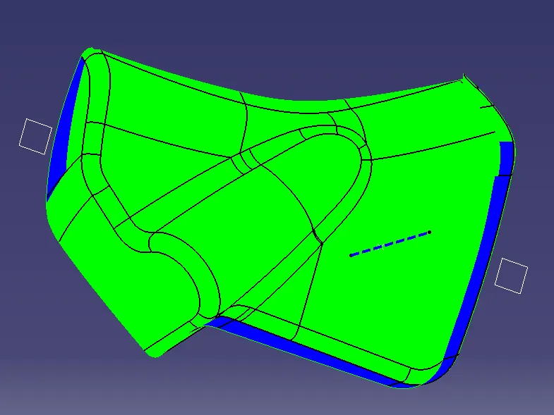
DRAFT ANALYSIS CLASS A SURFACE – LOWER SUBSTRATE
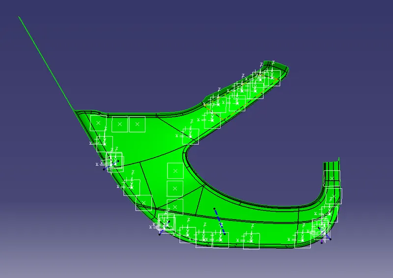
DRAFT ANALYSIS CLASS A SURFACE – ARM REST
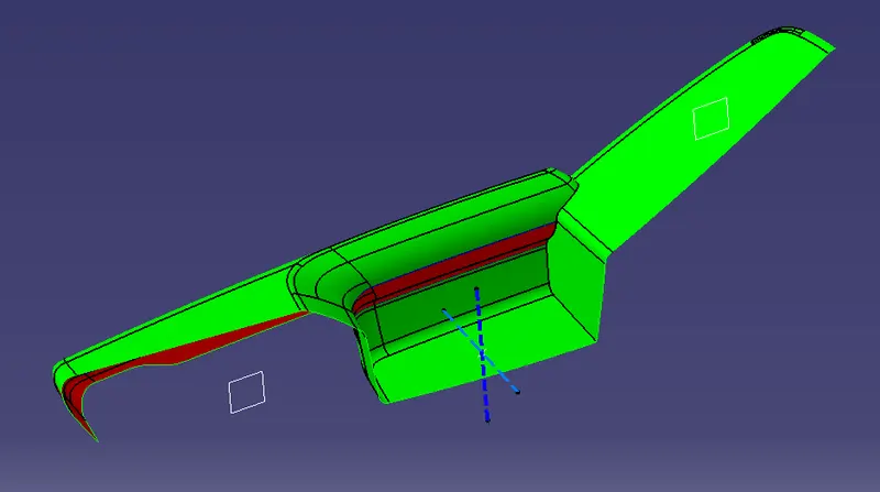
SIDE CORE
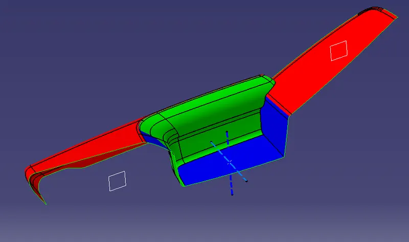
CLASS B SURFACE
In order to create the Class B Surface, first we have to refer the master section for wall thickness of the body and the direction of offset must be ensured. Now we know that the wall thickness is 2.5mm and the offset is done. We have the Class B of MAP POCKET ready, also used multi section to create missing faces during offset. Similarly do the same for the other trims.
CLASS B SURFACE MAPOCKET 1
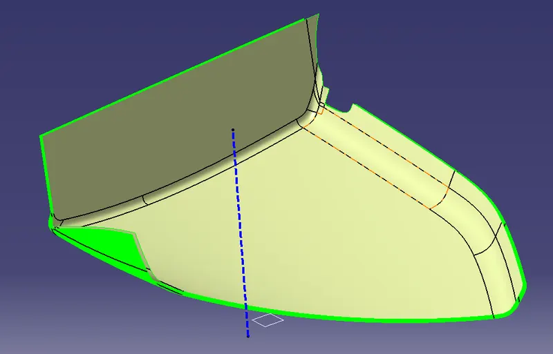
CLASS B SURFACE MAPOCKET 2
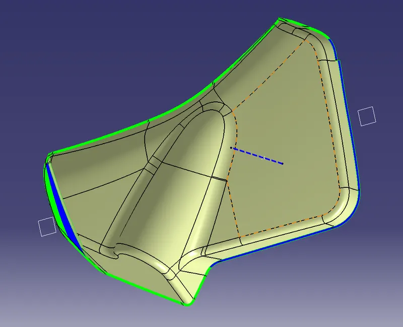
CLASS B SURFACE LOWER SUBSTRATE
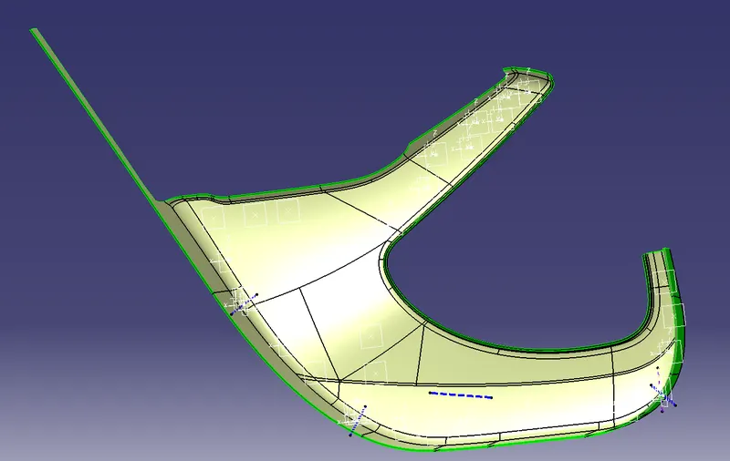
CLASS B SURFACE ARM REST
CLASS C SURFACE
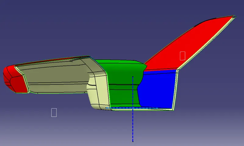
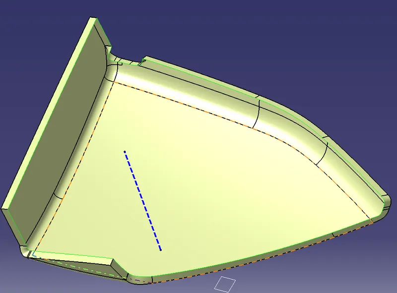
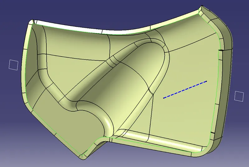
Class C Surface is created with respect to Class A. Here we create a boundary with the Class A. Now click on Sweep command. Sweep Dialogue box appears. Select the option 'with reference to Surface', select the guide curve and the reference surface. Then set the draft angle to 70deg inward/outward accordingly. Set the desired length and Hit OK. Join the C surface with A using Join command. Make sure all the surfaces intersect between CLASS A, B&C. Then perform Trim command to join the surfaces A, B and C. Do the same as well to the other surfaces.
CLASS C SURFACE MAP POCKET 1
CLASS C SURFACE MAP POCKET 2
CLASS C SURFACE LOWER SUBSTRATE
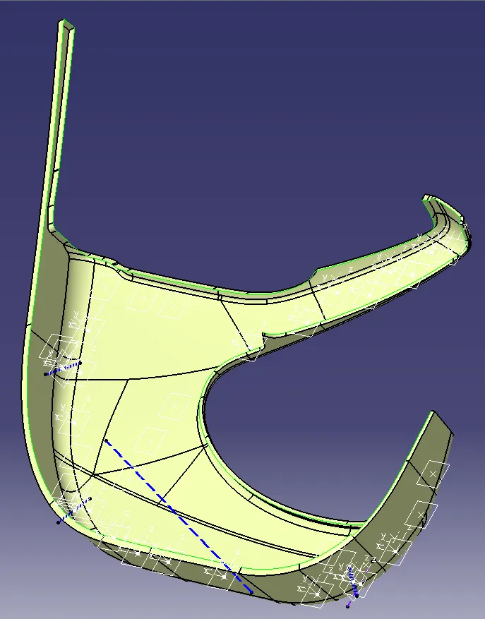
CLASS C SURFACE ARM REST
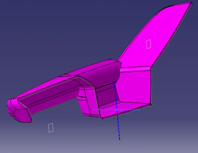
SOLID BODY
After Class A, B&C All the trims are converted into a Solid Body with Close Surface Command.
SOLID BODY MAP POCKET 1
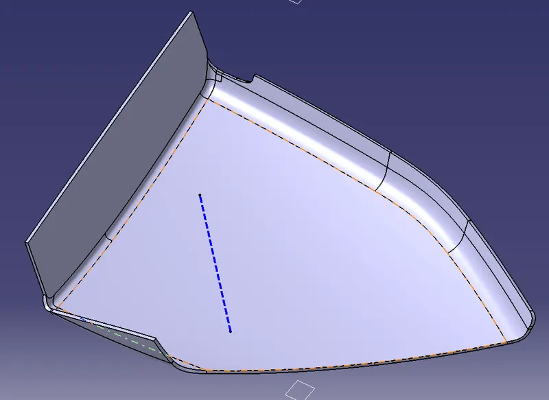
SOLID BODY MAP POCKET 2
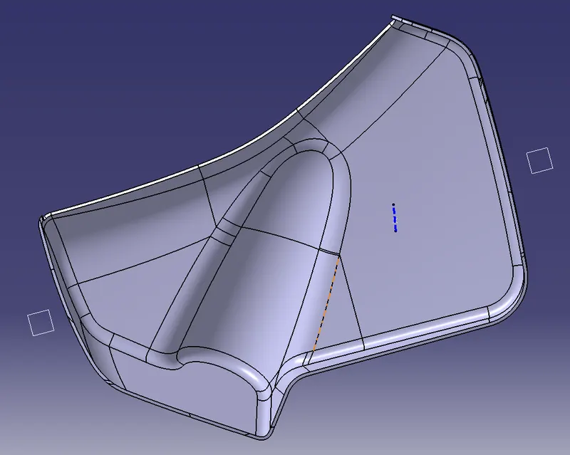
SOLID BODY LOWER SUBSTRATE
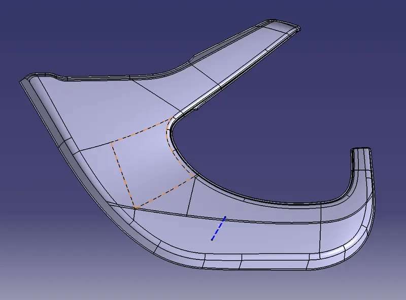
SOLID BODY ARM REST
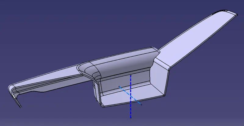
DRAFT ANALYSIS SOLID BODY with 3degrees
Draft Analysis performed on the Solid body with the draft parameters. Now we can see that the surface falls under the draft direction and hence the Tooling direction is accurate.
DRAFT ANALYSIS SOLID BODY – MAP POCKET 1
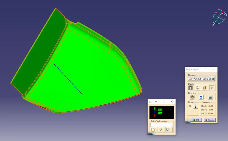
DRAFT ANALYSIS SOLID BODY – MAP POCKET 2
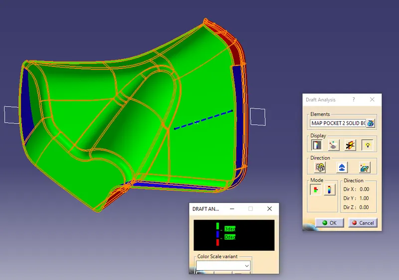
DRAFT ANALYSIS SOLID BODY – LOWER SUBSTRATE
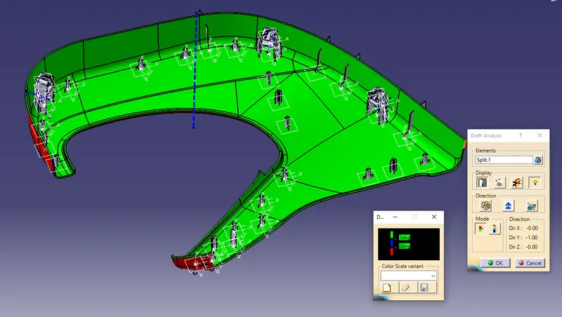
DRAFT ANALYSIS SOLID BODY – ARM REST
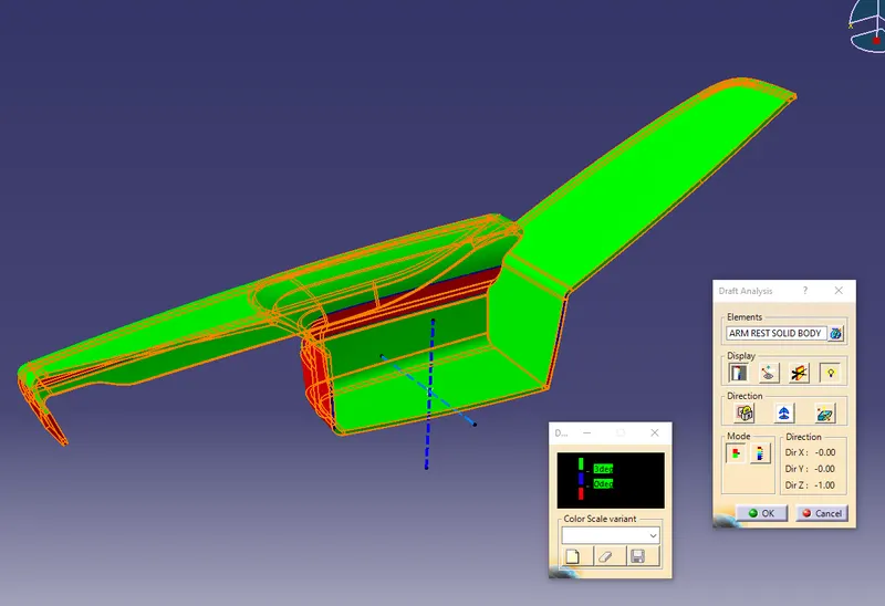
SIDE CORE
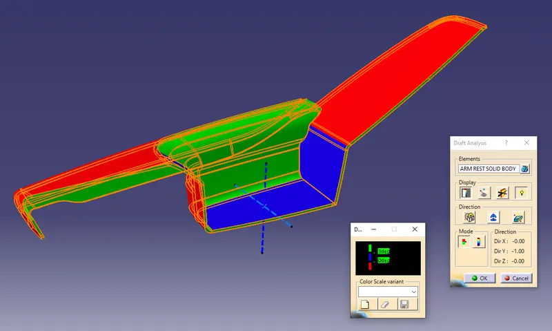
DRAFT ANALYSIS SOLID BODY ATTACHMENT FEATURES with 0.48degrees
DRAFT ANALYSIS SOLID BODY AF – MAP POCKET 1
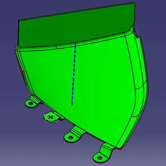
DRAFT ANALYSIS SOLID BODY AF – MAP POCKET 2
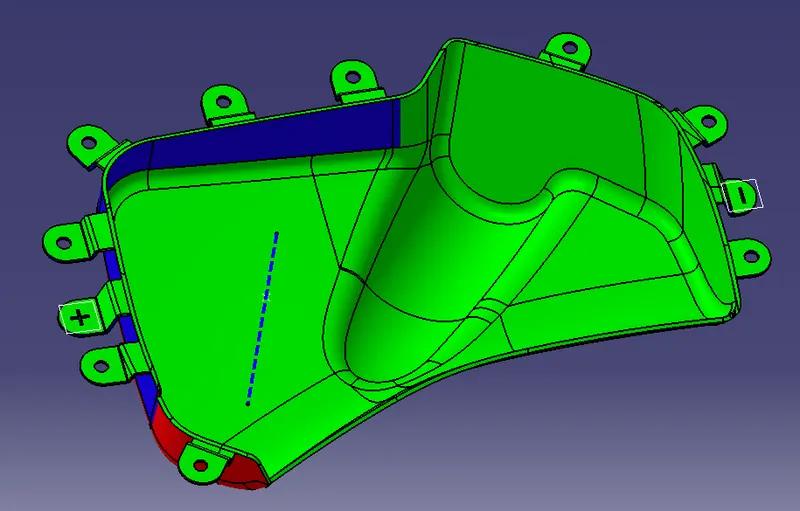
DRAFT ANALYSIS SOLID BODY AF – LOWER SUBSTRATE
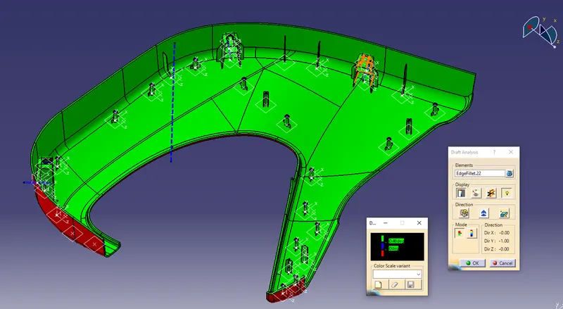
DRAFT ANALYSIS SOLID BODY AF – ARM REST
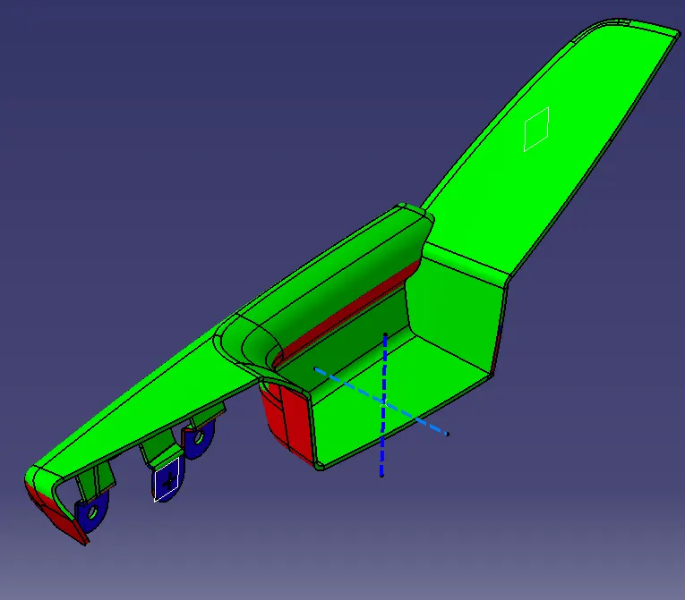
SIDE CORE
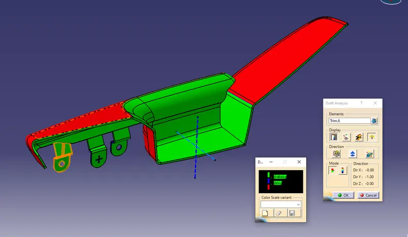
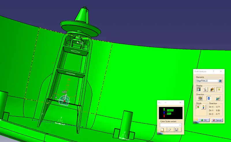
DRAFT ANALYSIS DOG HOUSE SIDE CORE
ATTACHMENT FEATURES
DESIGN GUIDELINES FOLLWED
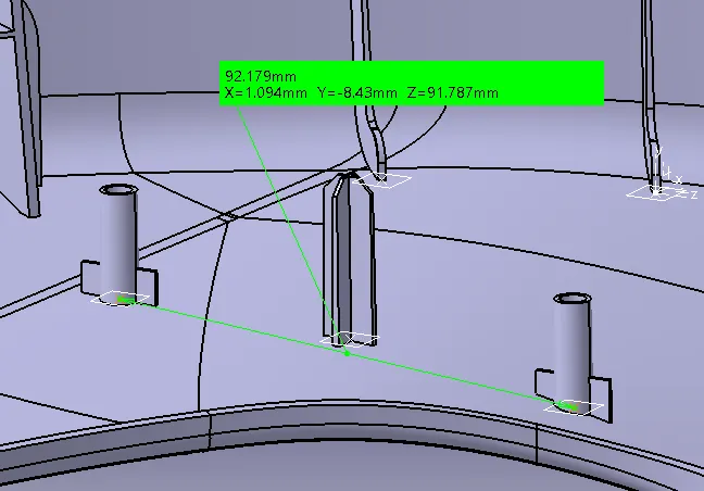
Creation of Heat Stakes with Ribs and Locators are followed as per the Design Guidelines
Heat Stakes – Height 20-22mm; Draft ≥ 0.5 degrees; Distance between two Heat stakes 65-100mm; Fillet 0.25mm
Heat Stakes Ribs – Width 0.8mm ((0.4t) t – wall thickness); Height 6-8mm; Draft ≥ 0.5 degrees; Rib Thickness at the Tip ≥ 0.75mm; Fillet 0.25mm
Locators – Height 5mm > than Heat Stake, Draft ≥ 0.5 degrees; Chamfer 4mm; Fillet 0.25mm
Dog House – Outer Draft ≥ 3 degrees, Inner Draft ≥ 0.5 degrees; Wall thickness at the intersection of the part wall (C) should be 40% or less than the main wall stock (T); Height of B 3-6mm
HEAT STAKES with RIBS & LOCATORS – LOWER SUBSTRATE
Heat staking also known as thermoplastic staking is the process of joining two dissimilar materials together. In heat staking, we use local heating and cooling to raise the temperature of plastic components and allow plastic reforming to be carried out. This reforming can be used in a wide variety of applications.
"Locating Devices" describes the components used to position a work piece in a work holding device. Locating is a crucial part of effective work holding.
Now we have to create the Heat Stakes with Rib, Locators 4Way & 2Way and Support Ribs as per requirement. Created sketches and extruded the surface along the tooling direction. Performed Draft, Chamfer and Fillets as per Design rules. Union trimmed the locators and Heat stakes with the main body Door applique. Locators 4way & 2way are used to arrest the 6 degrees of freedom.
FLANGES – MAP POCKET 1, 2 & ARM REST
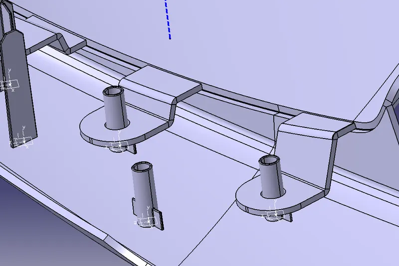
Flanges are a feature in plastic injection molded parts. They are provided to make contact with the mating part example - Heat Stakes and Locators.
Here I designed the flanges according to the Heat stake Ribs Tip. Sweep command is used to create step like flange. Split and Trim command used wherever required. Since the parts had variable surface structure the flanges were designed individually.
SUPPORT RIBS
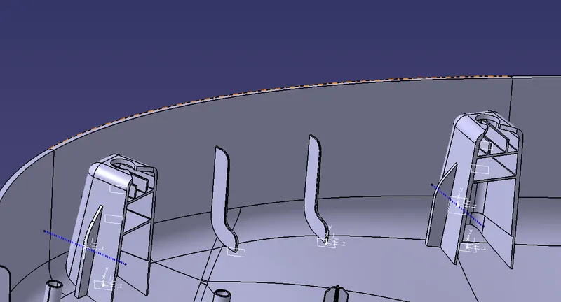
Ribs are a feature in plastic injection molded parts. They are thin extensions that run perpendicular from a wall or plane. They are commonly used to provide additional support and strength to a part. Thickness and location are essential to rib design.
DOG HOUSE
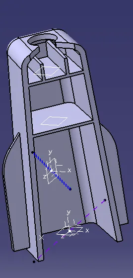
Dog house is an engineering feature used in plastic trim design. Dog houses are used as supporting feature. Dog houses are subjected to draft analysis to prevent breakage of the component during ejection from mould cavity. Dog house and other engineering components are built on B-surface.
PUSH PINS
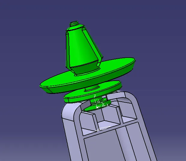
Push Pins are a type of light duty plastic fastener used to secure two or more items together. They usually snap into place as the grommet expands upon insertion. These “plastic fasteners” are typically made of plastic or nylon but some are available in metal.
BOOLEAN OPERATION
Boolean operation is an important feature in CATIA V5. Types of Boolean operations include Assemble, Add, Remove, Intersect, Union Trim, and Remove Lump. The Assemble command basically works considering the polarity of the solid bodies. One may be interested to know what actually the polarity of a body is.
Here the Heat stakes, Ribs & Doghouse are fixed with lower substrate using Union Trim (Boolean operation). The flanges are fixed with the Map pockets and Arm Rest. The faces which are not required are removed with faces to remove option. Union Trim will add and trim the body at the same time.
PARTING LINE
A parting line, in industrial casting of molds, is the border line in which draft angles change direction. One can check the parting line in the mould or product which divides the two half, i.e; the core and the cavity of a molded part.
DOOR TRIM FINAL OUTPUT