Week 6
AIM:
In order to Realize Connections on the given LH REAR DOOR – FE MODEL in ANSA using NASTRAN solver Deck.
- IMPORT THE .NAS FILE TO ANSA
- SET PID
- NUT AND BOLT CONNECTIONS
- RBE2 CLUSTER CONNECTIONS
- ASSINGNIG THE MASS VALUE for DOOR HANDLE
- SPOT WELD CONNECTIONS
- CBUSH CONNECTIONS
- ALIGNMENT OF CBUSH CONNECTIONS TO GLOBAL AXIS
PROCEDURE:
Import the LH REAR DOOR - FE into ANSA.
SET PID:
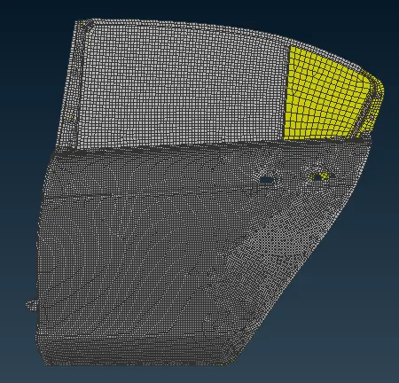
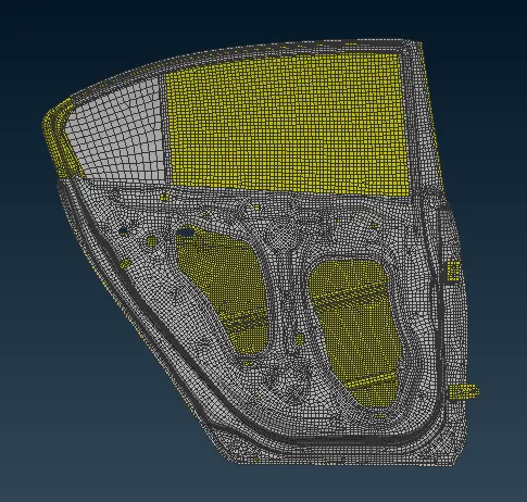
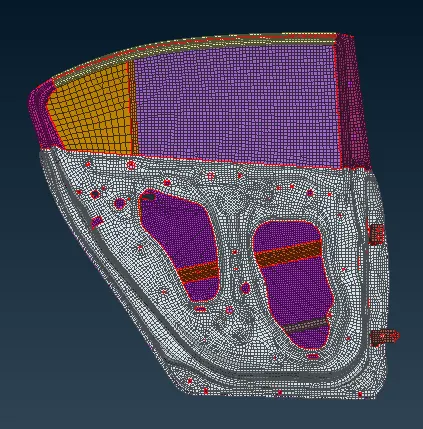
After importing the FE model with NASTRAN input Solver, Individual PID has to be assigned for each FE parts in order to work with connections. To do so, Use (!NOT) command and select the surface of the FE part with PID reg ON. So that the particular part is selected. Then, on middle mouse click selected entities that will remain visible. Now TOPO Modules > FACES > SET PID. Window select the visible Faces/Shell and on confirmation the PID Tab popups. New > PSHELL > PART NAME > OK. Similarly do the same for the other parts. The below Fig. shows the individual PID for each part.
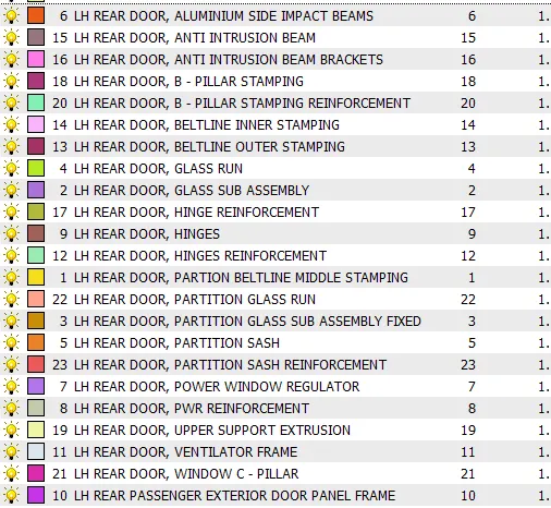
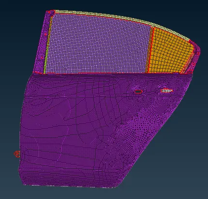
Now we can see in the below Fig. Each Part has different color that represents each one is saved as an individual PID.
NASTRAN SOLVER (DECK)
NASTRAN is a Finite Element Analysis solver (Deck) for stress, vibration, buckling, structural failure, heat transfer, acoustics and aero elasticity analyses.
NUT AND BOLT CONNECTIONS:
There are two connection methods.
- Automatic Connection using Connection Manager and
- Manual method by using RBE2 Connections.
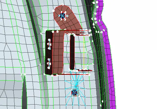
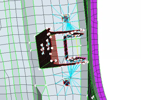
I used the manual RBE2 connection method. To do so, NASTRAN Deck Modules > ELEMENTS > RBE2 > Many node RBE2. “RBE2 Many nodes” pop up appears. We have to select the Slave Nodes and Master Nodes. Slave Nodes are (Dependent Nodes) and Master Nodes are Independent Nodes. Slave Nodes will behave depending on the Master Nodes. Now in FEATURE SELECTION Turn on LOOP command. In the FE we have a NUT and BOLT Connection on the HINGE area. The Nodes present on the Edge of the Perimeter Hole are the Slave Nodes. Select the Slave nodes as the Nodal Entity. Middle mouse click. It displays the number of nodes selected. Click next. On confirmation the Master node is created automatically based on the position of Slave Nodes. Again middle mouse click. Create Entity - popup appears. The connection created has a unique Element ID (EID), a Master ID (GN), No. of nodes. CM – Degree of Freedom. We have set the DOF as 123456. So the connection does not move. Hence it’s a rigid connection. In order to save the connection Create Entity > Part > Ask Always and click on Finnish. A MODEL BROWSER pop up appears. New > Part > Rename the Part ID and double click on the ID. Now the connection ID has been assigned. Now we have to make a rotational connection for the HINGES. To Do so, NASTRAN Deck Modules > ELEMENTS > RBE2 > Two node RBE2. Select the two Master Nodes and middle mouse click. RBE2 (RBE2) Popup appears. Name it and set the CM (DOF) as 12345. It represents the rotational movement of the door on the Z – Axis. Hit OK. Now the Hinges are created. Similarly do for the other Bolt and Hinge connections. The below Fig represents the NUT and BOLT and Hinge Connections.
RBE2 CLUSTER CONNECTIONS:
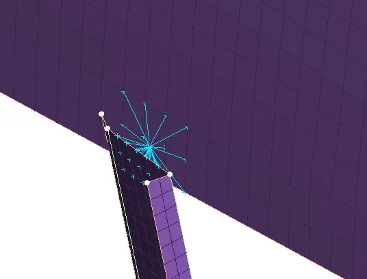
For RBE2 CLUSTER CONNECTIONS, I used the same manual RBE2 Command. To do so, NASTRAN Deck Modules > ELEMENTS > RBE2 > Many node RBE2. “RBE2 Many nodes” pop up appears. Now in FEATURE SELECTION click on the ++Nodes++ command. It’ll change to Entity selection. Now do element selection and middle mouse click, following the previous method will do the work. Here only the Command of selection and connection method varies. Here four nodes are selected in each element. The below Fig. represents the RBE2 CLUSTER Connection between the power window regulator and the Glass. This type of connection is alos called as RBE2 Spider.
The power window regulator part is extended using Mesh Modules > Grids > MV free – set the direction to Z axis and extend. Then do a RECONSTRUCTION and SMOOTH.
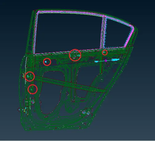
Other RBE2 Cluster Connections.
ASSINGNIG THE MASS VALUE for DOOR HANDLE:
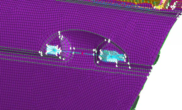
For door handle, I used the manual RBE2 Many nodes. Deployed two rigid connections and with same Many nodes, we have to select two master node and on confirmation we have a center node where we have to assign MASS for the door handle.
To do so > NASTRAN Deck Modules > ELEMENTS > CONMi > CONM2 > Nodes – CONM2 (CONM2) Popup appears. Name the CONMASS and in M we have to assign the MASS. M(MASS) Convert 100 Gram to Tonne. We get 1e-4 in Tonne. Mass should be assigned only in Tonne. Then Hit OK. Now we have assigned the MASS for the door handle. The below Fig shows the representation.
SPOT WELD CONNECTIONS:
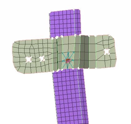
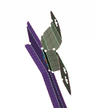
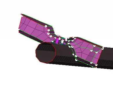
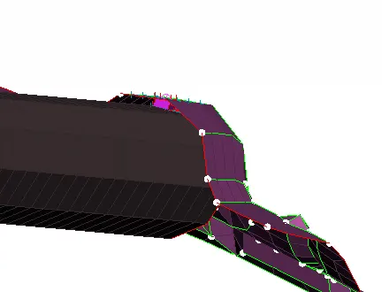
The SPOT WELD Connection method - Automatic Connection using Connection Manager. To do so – Go to TOPO Modules > POINTS > ON COG. Now select the middle FE curve on the Power Window Reinforcement surface and by middle mouse click a COG point is created. In the ASSEMBLY we have a command called CONVERT. This command converts the number of selected 3D-points, circle centres or Weld Points into Spot-weld Points, Bolts or Gum Drops according to the preferred selection. The connection points are used for the automatic definition and management of connection elements. Click on the CONVERT > 3D-points and select the COG point created. Middle mouse click. Connection type popup appears. Select the type of connection as SPOTWELD POINT. And hit OK. Now in ASSEMBLY > Connection Manager > Connection Selection Assistant popup appears. Select the converted SPOTWELD POINT and middle mouse click. CONNECTION MANAGER Popups. On the right side we have to represent the FE TYPE as RBE3-HEXA-RBE3. Then Assign P1 and P2 by modify > F1 > Select the P1 (POWER WINDOW REINFORCEMENT) and then click on enter to assign the P1 and same for P2 (POWER WINDOW REGULATOR). Then represent FE TYPE > as RBE3-HEXA-RBE3 > Search Distance as 20 > RBE3 PINFLAGS (DOF) as 123456 (since it is a spotweld connection, does not have any rotational movement). BODY > Create PSOLID ID (SHIFT + ?) > APPLY > REALIZE. Now the SPOTWELD connection is realized between POWER WINDOW REINFORCEMENT and POWER WINDOW REGULATOR. Simillarly other SPOTWELDs connections are realized. Below Image shows the representation.
CBUSH CONNECTIONS:
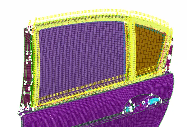
Here the CBUSH CONNECTIONS represents a Weather Strips. To do so – Go to MESH modules > PERIMETERS > FEAT2CURVE and turn on feature line selection. Now select the perimeter curves on both the glasses. On middle mouse confirmation Curves are created. ASSEMBLY > Convert > Curves. Select the curve. Middle mouse click. Connection Type > as SPOTLINE. Then in ASSEMBLY > Connection Manager > Connection Selection Assistant popup appears. Select the converted SPOTLINE and middle mouse click. CONNECTION MANAGER Popups. On the right side we have to represent the FE TYPE as RBE3-CBUSH-RBE3. In ID give the value 10 on “S”. Then Assign P1 and P2 by modify > F1 > Select the P1 (LH EXTERIOR DOOR PANNEL FRAME) and then click on enter to assign the P1 and same for P2 (LH REAR DOOR, GLASS SUB ASSEMBLY). Then represent FE TYPE > as RBE3-CBUSH-RBE3 > Search Distance as 50 > Interface – Keep all Branches checked > Body – Create PBUSH ID (SHIFT+?) > PBUSH HELP Window popups > Rename > And set the Standard values of K1, K2,K3, K4, K5 and K6 as K1 – 0.001, K2 – 0.001, K3 – 0.001, K4 – 10, K5 – 10, K6 – 10 and hit OK. APPLY > and REALIZE. Now we have created the CBUSH connection successfully. Similarly do the same for the other SPOTLINE created. The below Fig. shows the representation.
ALIGNMENT OF CBUSH CONNECTIONS TO GLOBAL AXIS:
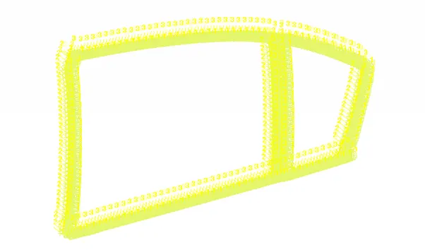
In order to ALIGN the CBUSH CONNECTIONS TO GLOBAL AXIS – Press F12 > Elements > CBUSH (Double click on CBUSH Property) > CBUSH ID popups. On the right side - show/ hide colums > Check ON Orient and CID. Now in the ID section, select all by (CRTL + A) and right mouse click > Modify. MODIFY WINDOW Popups. Right mouse click on New Modification 1 and Click New. New Modification 2 created. Then on the right panel > MODIFY RULES > Select ORIENT and next TAB > With Cord. Now click the + icon to create another TAB. Select CID > then feed the value as “0”. And hit OK. ANSA will ask for confirmation. On Confirmation now we can see that all the CBUSH ID’s CID value has been changed to “0” which represents all the connection are facing towards the GLOBAL AXIS. In Below Fig. we can see the representation.
Now, I have an idea of how connections work with commands both Manual and Automatic. Quite interesting. Proud to be a Mechanical engineer.
CONCLUSION:
- SET PID assigned.
- NUT AND BOLT CONNECTIONS realized.
- RBE2 CLUSTER CONNECTIONS realized.
- THE MASS VALUE for DOOR HANDLE has been assigned.
- SPOT WELD CONNECTIONS realized.
- CBUSH CONNECTIONS realized.
- CBUSH CONNECTIONS are aligned to the GLOBAL AXIS
Now we have realized all the necessary connections and the FE is ready for NVH simulation.