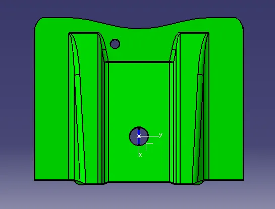
Week 8 - Challenge 2 - Base Bracket Design
AIM
To Create the Base Bracket Plastic component through the given Class-A surface. To begin with, the tooling axis for the given Class-A Surface should be created meeting the requirements of the draft angle and at the end perform the Draft analysis on the model.
- Import CAD file.
- Class A Surface
- Tooling Axis
- Publication
- Free Form Analysis
PROCEDURE
- Import the given BASE BRACKET - IGS file into CATIA V5 and Save it as .CATPart
Class A Surface
The Class A Surface of the BASE BRACKET is defined in the Geometrical Set. 1. Here we can see that the surfaces of the given CLASS A SURFACE is not topologically connected. In order to do that, select the Geometrical Set. 1 and perform a Join operation. Now we have a Topological Error where the surface has several self-intersecting edges. To solve the error we have to do some modification on the surface elements. So now we eliminate the surface which shows error. Look for the error surface and right click on it to clear the Selection. Now hit OK to Join. Create a new (Geometrical Set) CLASS A and add the Joined Surface. To get a closed geometry we have to use Multiple Extract Operation in the missing surface individually. Now use the Multi Sections Surface and select two individual multiple extract in the Section and Select the extracted guide in the Guide tab. Check whether the two section extracts are in the same direction and hit OK. Now one part of the surface is created. By using the Fill operation create the remaining surface and Join it again. And yes we have a closed geometry now. To ensure it use the Boundary Operation.
Tooling Axis
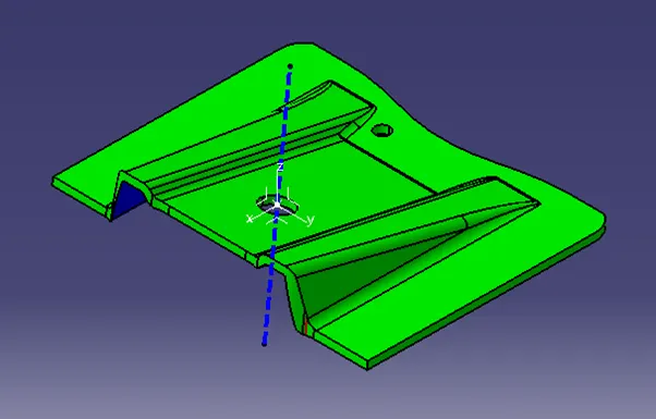
In order to create a Tooling Axis first we have to analyze the given Geometry. The Tooling direction we create determines the clearance on all the faces of the geometry. So that there won’t be any issue while ejecting the part from Core and Cavity. By analyzing the geometry we know that the clearance of tooling direction is on the Z Axis. In order to create a Tooling axis we need a point definition and Axis System. Create a Boundary using the center hole then plot a point and insert an Axis System. Now select the Intersection from Wireframe Tab and select the First element as YZ plane and second Element as CLASS A in the popup and hit OK. Now we have two lines on the YZ plane. With reference to the identical lines we create two parallel lines by setting the line type as point to point. We create these line in order to clear the tooling axis for the identical faces on the YZ plane. To get the Tooling Axis reference we bisect the parallel lines. To do that select the line command from wireframe set the line type as bisecting and select the parallel lines as line 1 and line 2 then the point as well. By doing that we have a bisecting line represented orange in color which shows the direction of the bisecting line. By taping on the color we can switch the direction we require. So now we have a reference line on the YZ plane to create the Tooling Axis. Similarly we create a reference line on the ZX plane. Now with the reference lines created, we bisect. The Bisecting line out of Line.4 and Line.7 is our final Tooling Axis. Then with Alt + ENT modify the properties i.e. color and thickness of the Tooling Axis.
Publication
Publication acts as a reference to the geometry. So before Draft Analysis we have to publish both the CLASS A and Tooling Axis.
Free Form Analysis
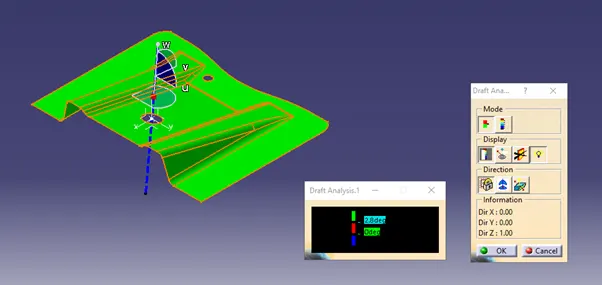
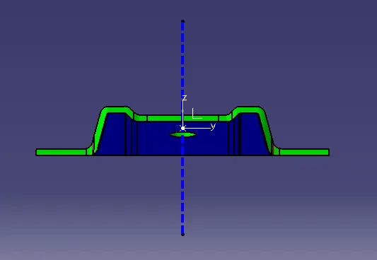
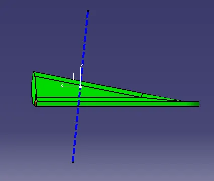
Free form Analysis is done to ensure the part we drafted is easily removed from the Core and Cavity. In order to do that Go to Insert > Analysis > Feature Draft Analysis. Now Draft Analysis popup appears. There in direction section select the compass to define the draft direction. Drag the compass and place it on the Tooling Axis direction, then lock the draft direction. Now select on the Class A Surface which shows the positive and the negative angles in two different colors. Green is Positive angle and Blue represents the negative angle. The third one is red which represents angle closer to 0 degree. The Draft Analysis is performed by specified values. So we have only positive and negative angle with that finally we come to a conclusion that we have a proper tooling direction.
DRAFT ANALYSIS REPORT – CLASS A SURFACE
DRAFT ANALYSIS REPORT – SOLID BODY
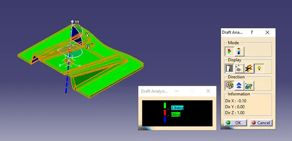
DRAFT ANGLE IN VARIOUS ORIENTATIONS
ISOMETRIC VIEW
FRONT VIEW
RIGHT SIDE VIEW
TOP VIEW