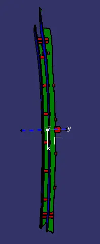
Week 9 - Project 1 - Door Applique Design with Engineering Features
AIM
To Create the Heat Stakes and the locators considering the design rules mentioned in the video for the door applique.
- TOOLING AXIS CREATION
- DRAFT ANALYSIS
TOOLING AXIS CREATION
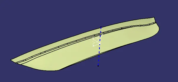
We have the Class A Surface provided for both Door applique and the fixture surface. In order to create the tooling axis, first we have to create a point at the center of the given Class A. Then we have to create an Axis system with the reference point. Here we don't have the necessity to use the intersection command to create a Tooling Axis. Since the given surface does not have any complex shapes we create a Tooling Axis with reference to the Point created at the center of the Axis system. Now we have our proper Tooling Axis for the given Class A.
DRAFT ANALYSIS
The Draft Analysis command allows us to detect if the part we drafted will be easily removed. This type of analysis is performed based on color ranges identifying zones on the analysed element where the deviation from the draft direction at any point, corresponds to specified values.
In order to perform the draft analysis in the given Class A, we use the Feature Draft Analysis. Command. Now a draft analysis Dialogue box appears.
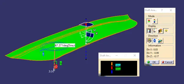
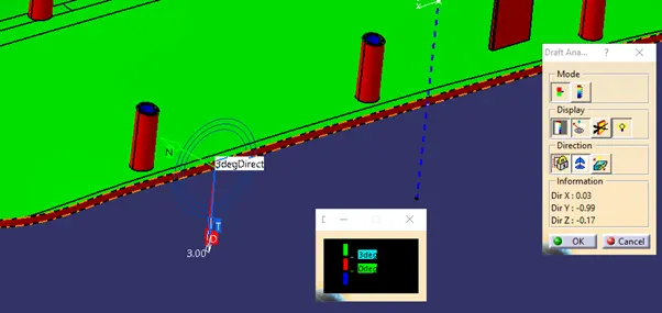
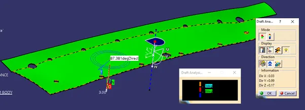
Here we have the color scale (Mode), Display and Draft direction. With this we can identify the maximum and minimum values for the analysis. Now click on the compass from Direction. Then grab the compass and place it on the Tooling Axis. Set the maximum draft angle as 3deg and minimum as 0 in the Display Quick mode. Then lock the compass direction and click on the Class A Surface. Now we can see that the surface falls under the draft direction and hence the Tooling direction is accurate.
CLASS B SURFACE
Now by using the class A extract surfaces to create Class B Surface. Extrapolate the surface and trim the surface. We have the Class B.
CLASS C SURFACE
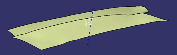
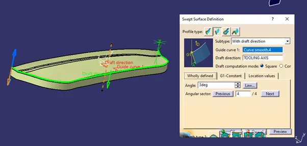
Class C surface is created with respect to Class A. Here we create a boundary with the Class A. Now click on Sweep command. Sweep Dialogue box appears. Select the option 'with draft direction' and draft direction as Tooling Axis. Then set the draft angle to 3deg inward/outward accordingly. Hit OK. Join the C surface with A using Join command. Make sure all the surfaces intersect. Then perform Trim command to join the surfaces A, B and C. Do the same as well to the fixture surface. Now create a closed volume.
LOCATORS AND HEAT SATKES
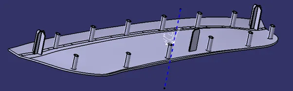
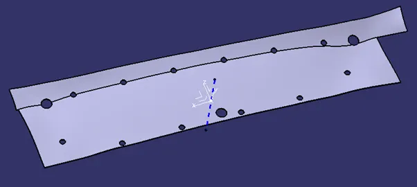
Now we have to create the 4 way locators and heat stakes as per requirement. Created sketches and extruded the surface along the tooling direction. Performed Draft, Chamfer and Fillets as per Design rules. Union trimmed the locators and Heat stakes with the main body Door applique. Created holes in the fixture surface where the locators and heat stakes meet.
DRAFT ANALYSIS ON SOLID BODY
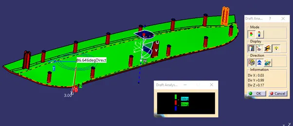
Performing draft analysis on the Solid body with the draft parameters. Here we can see that the part falls under the given draft angle and will be easily removed.
SOLID PART DOOR APPLIQUE
SOLID PART FIXTURE
SOLID PART IN VARIOUS ORIENTATION
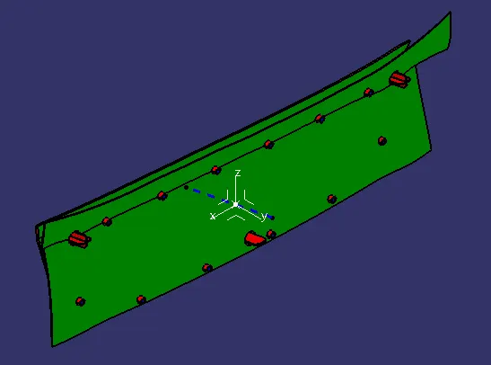
ISOMETRIC VIEW
FRONT VIEW
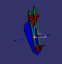
RIGHT SIDE VIEW
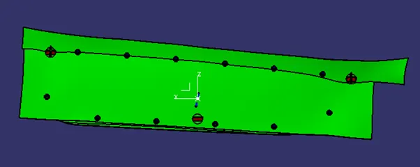
TOP VIEW