Design of backdoor
AIM
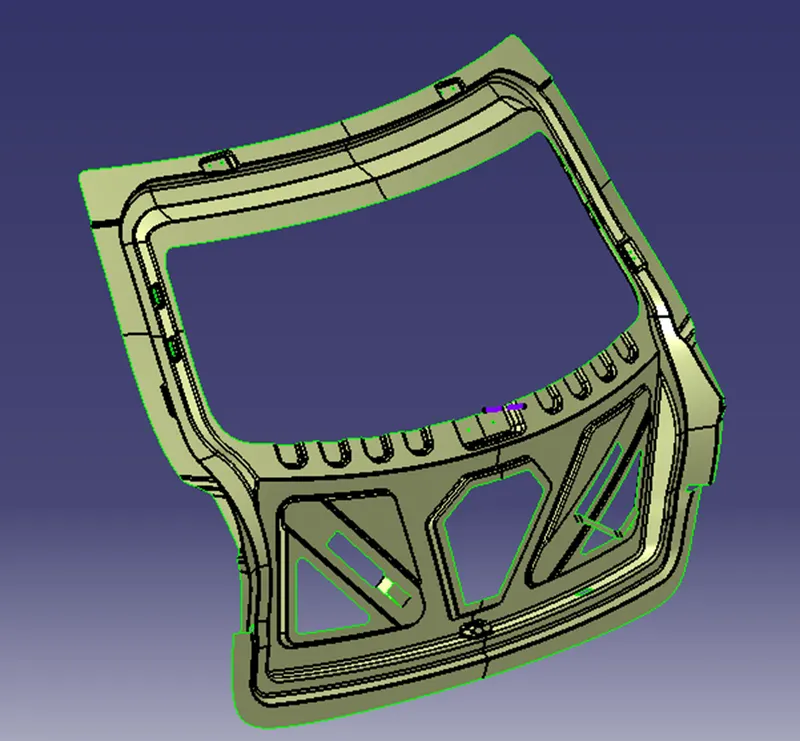
To design a backdoor with appropriate design methodologies. And provide necessary reinforcements, embosses from the given styling surface.
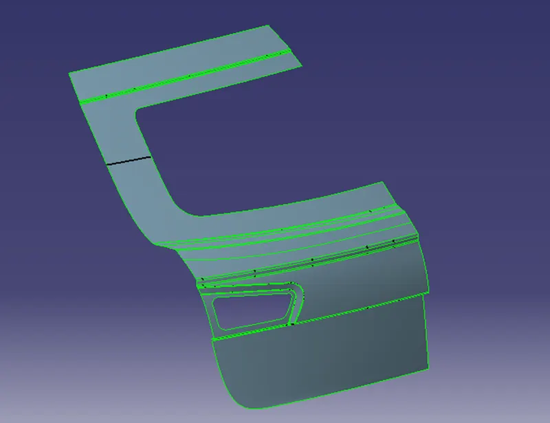
GIVEN STYLING DATA
PROCEDURE
BACKDOOR
A hinged hatch at the rear of a vehicle that can be lowered for loading and unloading.

BACKDOOR OUTER PANEL
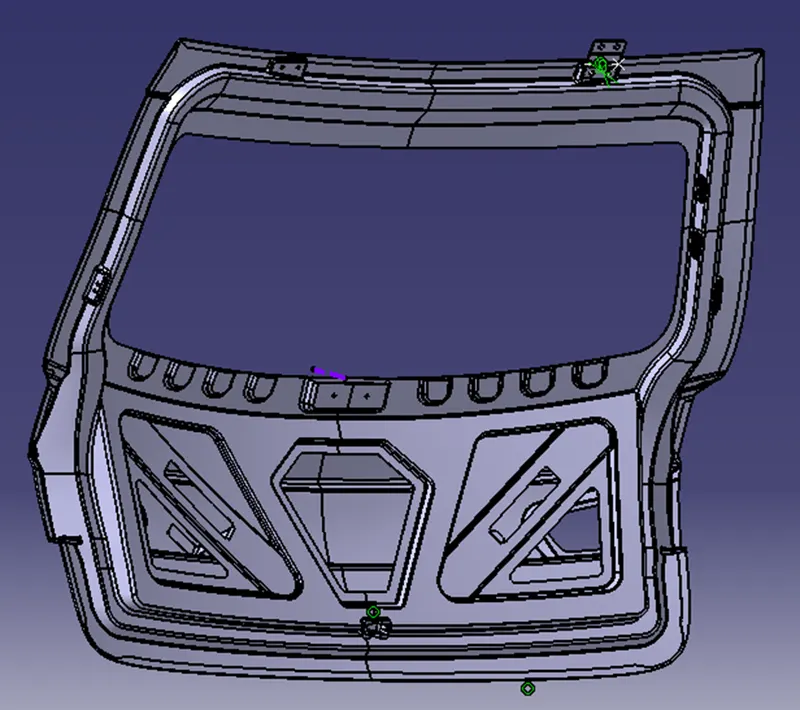
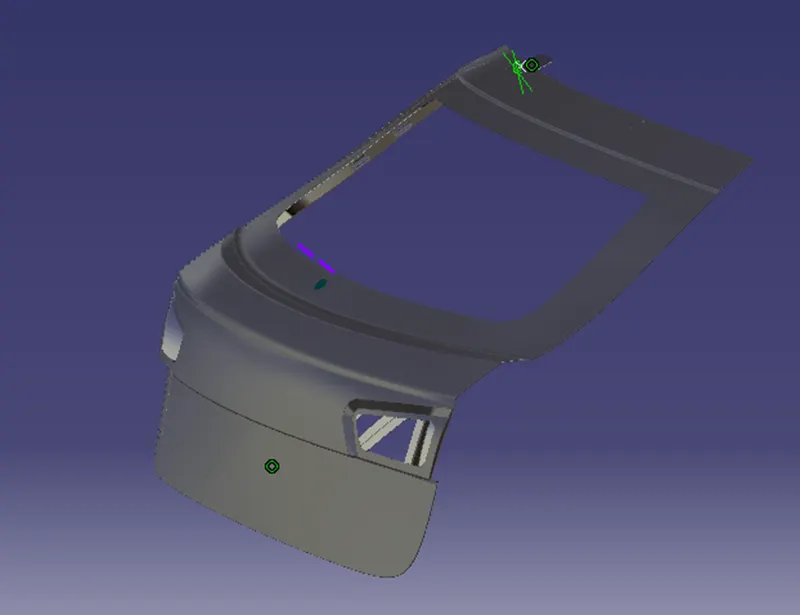
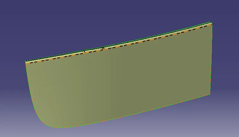
Here we have two styling surface which is the backdoor outer panel upper and lower. These two are practically spot welded together.
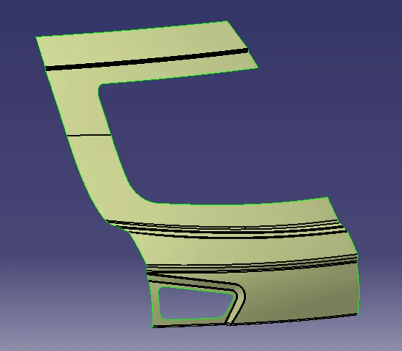
BACKDOOR OUTER PANEL - REFINED SURFACE
To refine the surface I extracted the given surface one by one and did multi section with support provided for tangency and in some areas shape fillet were used.
BACKDOOR OUTER PANEL UPPER
BACKDOOR OUTER PANEL LOWER
BACKDOOR INNER PANEL
SEALING FLANGE
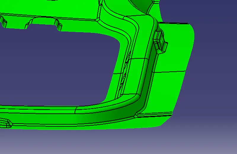
Sealing Flange is designed in such a way that the backdoor locks perfectly with the rubber seal so that dirt or water doesn’t enter inside the cabin.
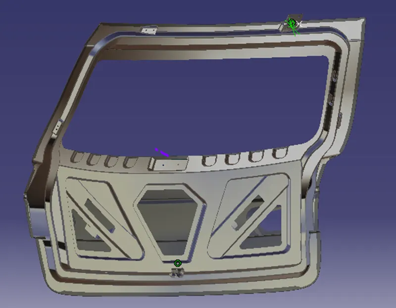
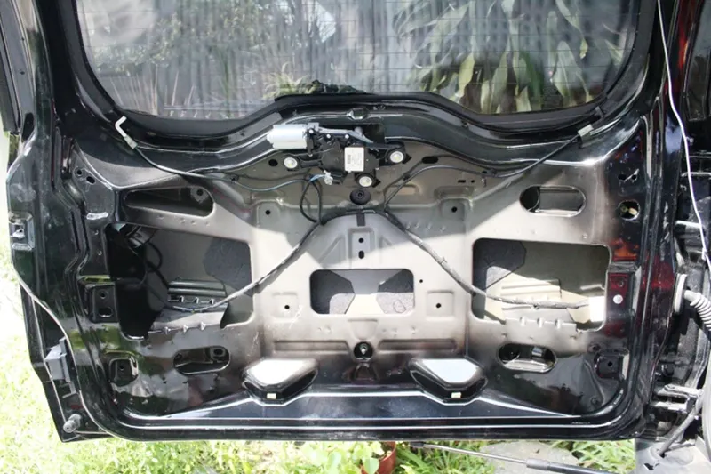
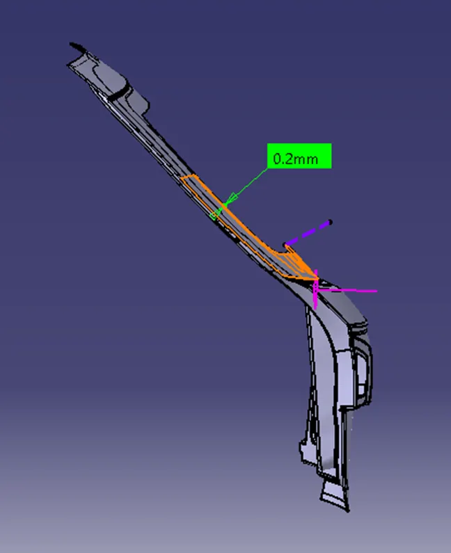
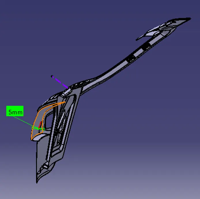
Backdoor inner panel can be structurally optimized with Embosses and reinforcements in order to improve stiffness and impact behaviour. The 0.2mm hemming gap provided between the inner and outer panel flange for the mastic adhesive to ooze out and stick together. 5mm gap provided between Outer panel and Inner panel mastic bend which gives additional stiffness during rear impact.
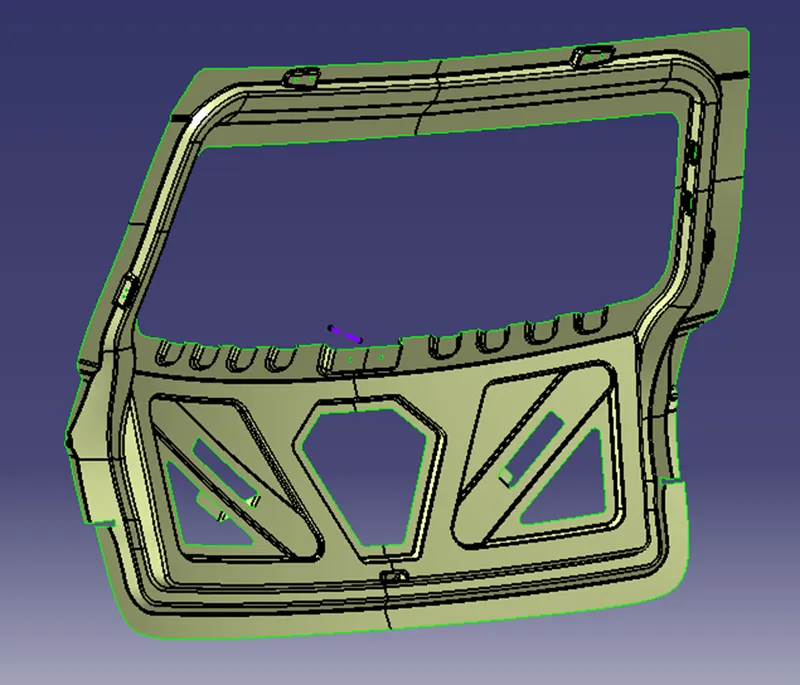
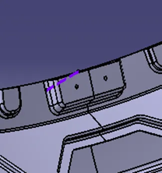
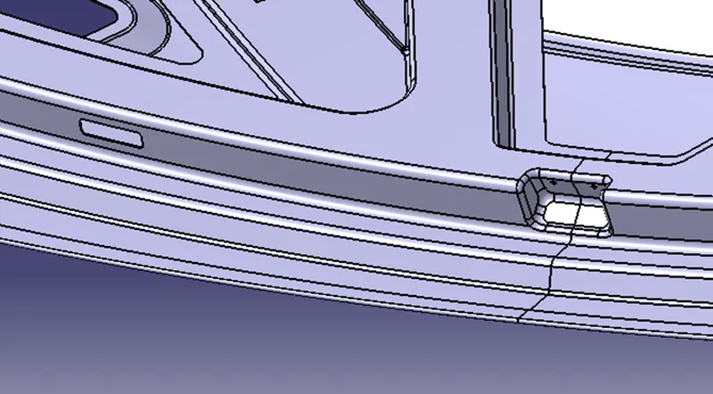
Inner Panel has Hinge mount, Gas stay mount, Wiper Mount and Latch Mount.
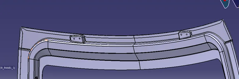
HINGE MOUNT
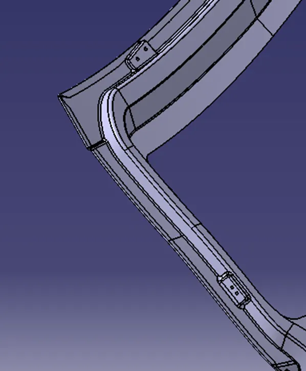
GAS STAY MOUNT
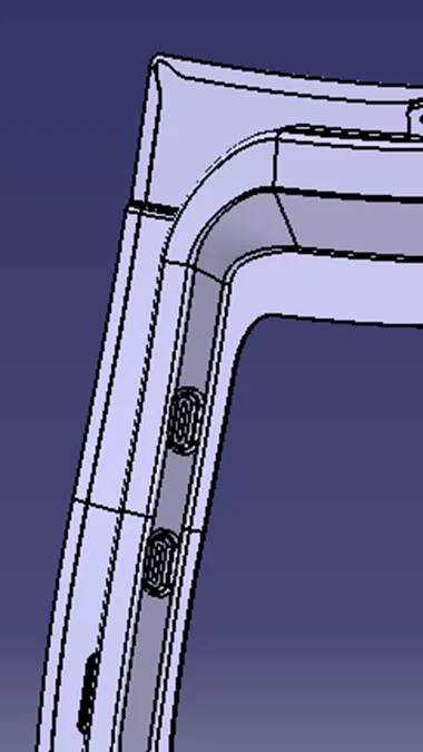
SLOT MOUNT
WIPER MOUNT
LATCH MOUNT AND CLOSURE HANDLE SLOT
MASTICS
The use of automotive adhesives & sealants is widespread, from something as small as a sensor to something as large as a vehicle chassis. Many high-performance cars are produced with lightweight composite materials to keep the weight of the vehicle minimal. These composite materials are unable to be welded and the use of mechanical fasteners adds to the vehicle weight, as well as being unsightly and at risk of vibrating loose. Structural adhesives are very much a favourite amongst automotive industry professionals, as they allow different types of material to be joined together easily (such as composite to metal where welding would not be suitable). An added advantage is the rubber toughening present in structural adhesives which helps absorb vibration and impact forces.
MASTIC BEND
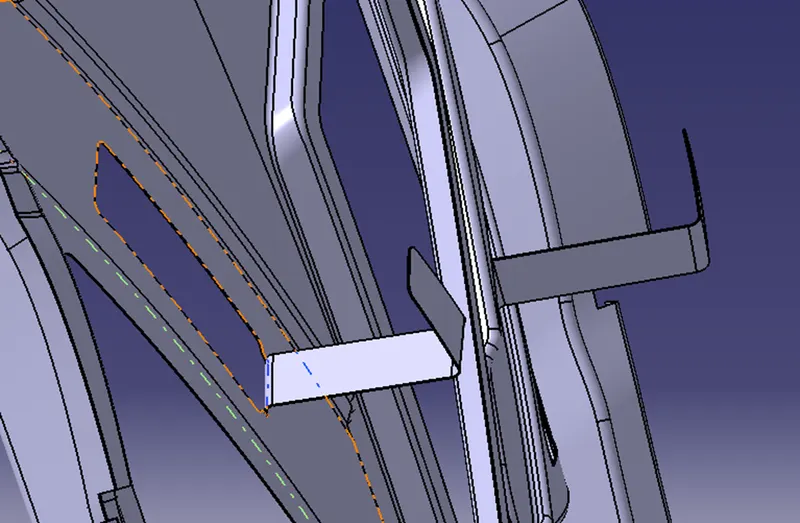
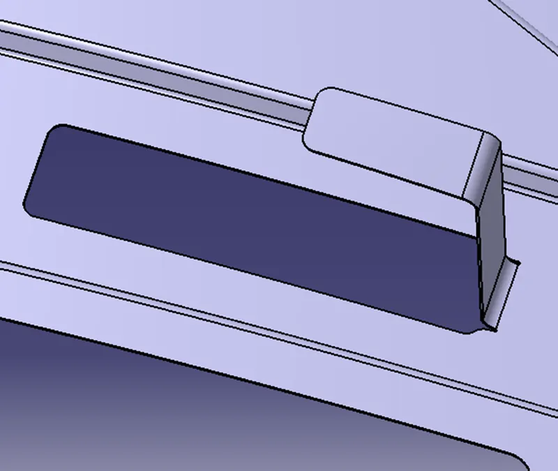
The mastic bends provide additional stiffnes to the backdoor and reliefs are provied where the steel is bent in order to avoid crack or damage.
HINGES
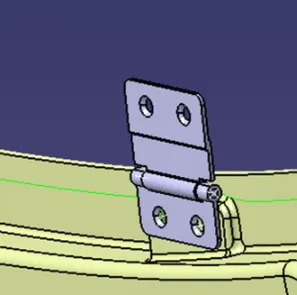
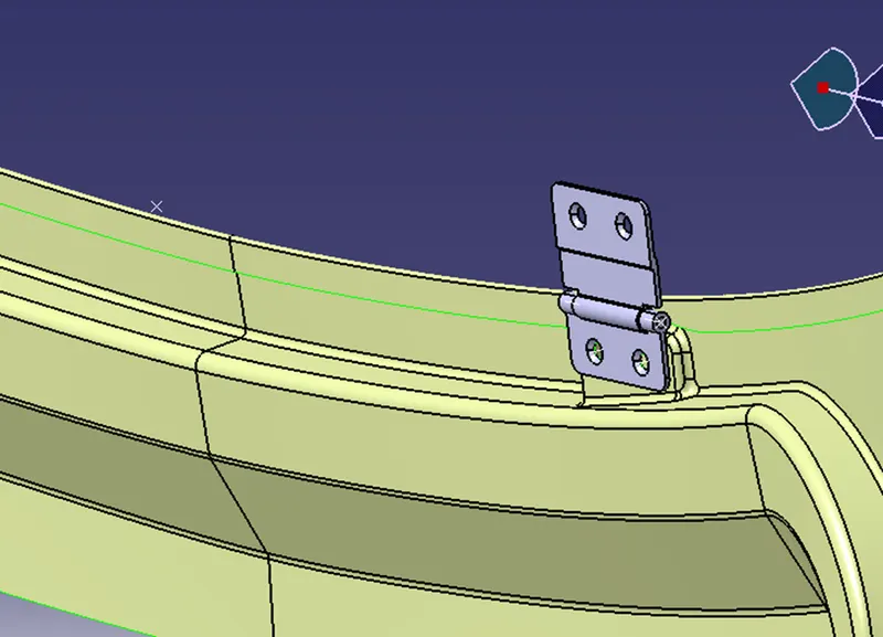
Hinge mechanism includes upper and lower brackets interconnected by pivoted links. An auxiliary hinge member is pivoted to the upper bracket and secured to the Back door. The lower bracket is secured to the body. The upper hinge bracket and auxiliary hinge member are releasably secured to each other and normally move together as the Back door moves between closed and partially open positions. When the auxiliary hinge member is released from the upper hinge bracket, the Back door can be moved to various further open positions
LATCH
Latch is designed for long-lasting use. Its durable steel construction safeguards against body damage, ensuring the vehicle hood won't unexpectedly open while driving.
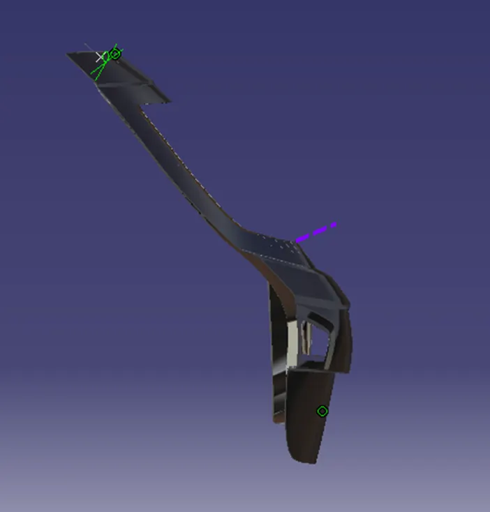
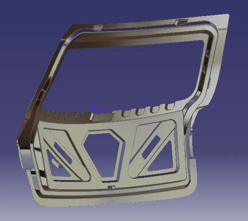
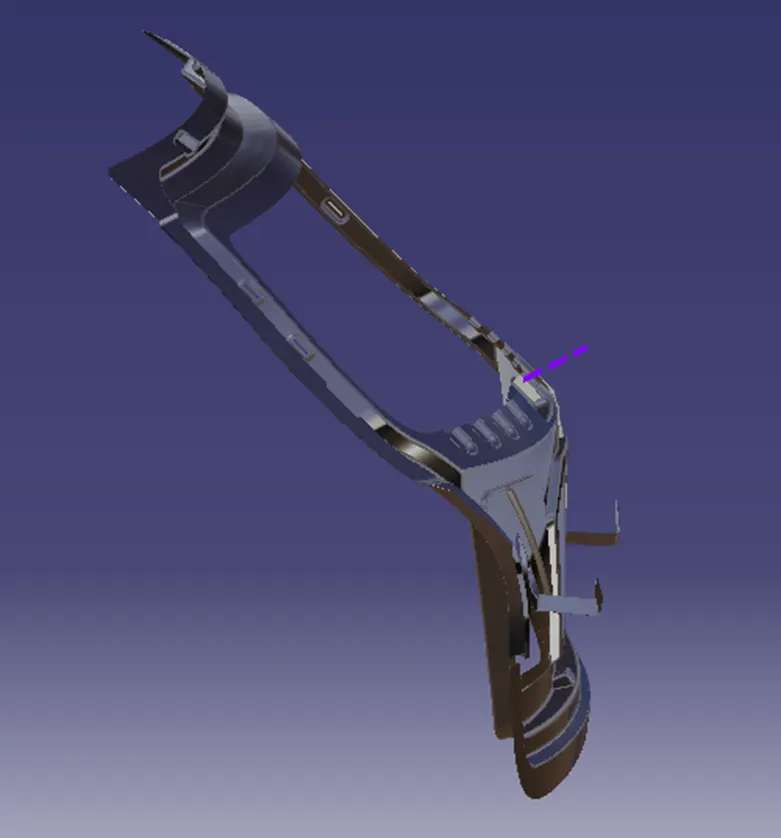
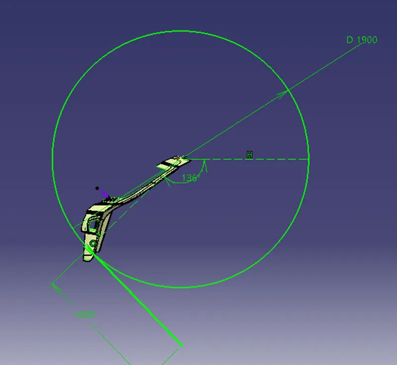
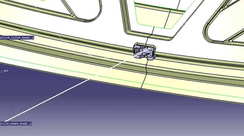
Latch Trajectory location is fixed from the Hinge data. First the Hinge is constrained with the mount. Then from the pivoted link of the Hinge a centre reference point created to get the perpendicular Axis for the latch as shown in the sketch below.
FRONT & REAR RELIEF
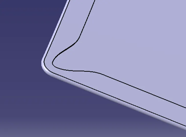
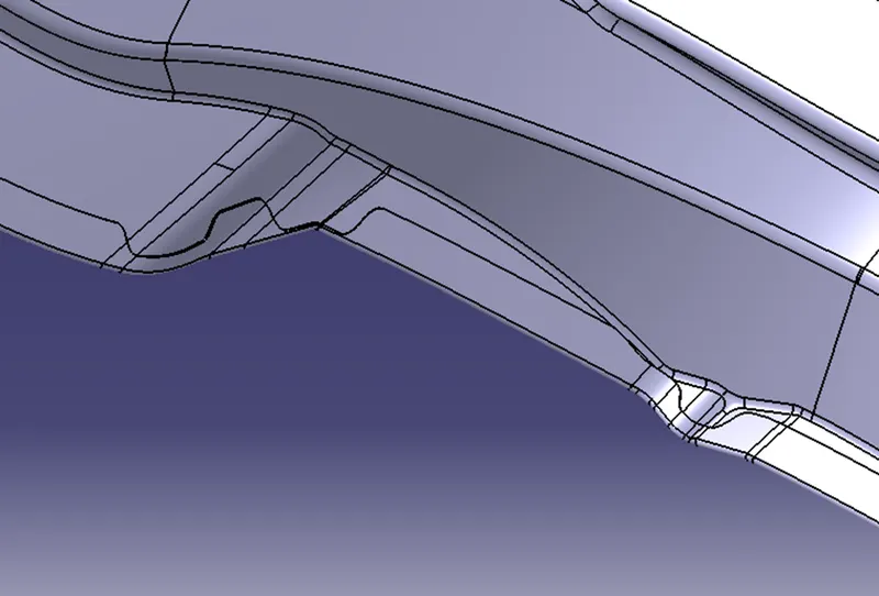
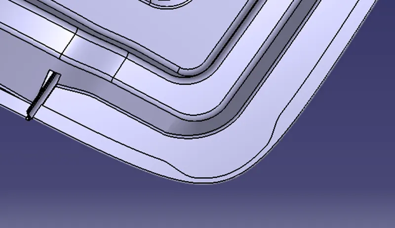
In custom sheet metal fabrication, the structural integrity and forming accuracy of a manufactured part is essential to its utility. For a part to perform as expected, the sheet metal must be bent accurately without tearing or warping around the bend. Achieving the perfect bend can be challenging in certain formed features. To counter metal's natural tendency to deform around the bend, it's sometimes necessary to add a bend relief.
In sheet metal, a bend relief is an incision cut along the sides of a planned bend. Though bend relief lengths and widths vary between projects, they all share a common goal preventing tearing and part deformation during the bending process. During the bending of sheet metal, material around the bend tends to stretch and deform. The metal between a bend and a flat surface, if there is any, tends to stretch and tear as the bend is created, which results in a deformed and structurally weak component. A bend relief creates space between the bent and unbent surfaces so that the edge of the sheet metal is perpendicular to the bend itself. The gap between the bend and surrounding material allows us to shape the sheet in the press brake cleanly, eliminating cracking and tearing. Because a bend relief serves a simple purpose, you can choose its shape to meet the needs of your design. Common bend relief shapes include rectangular and obround (A shape consisting of two semicircles connected by parallel lines tangent to their endpoints). At minimum, the size of the bend relief should equal the material thickness plus the inside bend radius.
HEMMING
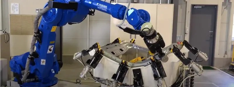
Hemming is a sheet metal forming process in which sheets are joined by bending it to 180°. Automotive body panels and automotive parts such as deck-lids, trunk-lids, doors, hoods and tailgates are formed by hemming process. In this process, usually a sheet is bent with the help of inner sheet in three different stages.
REINFORCEMENTS
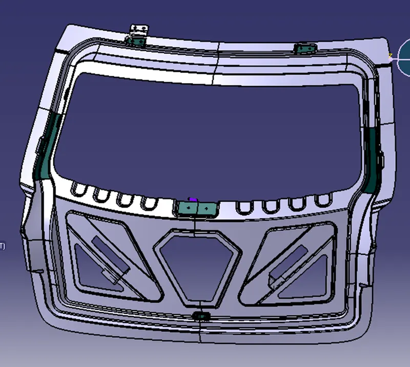
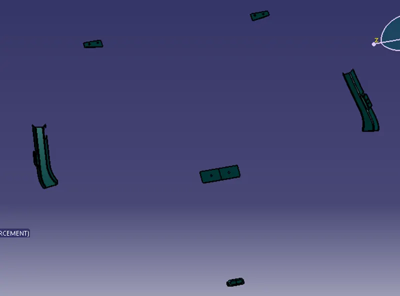
Vehicle Backdoor reinforcement structures are provided to reduce impact in collisions. In one visible form, the structure is to include a lower reinforcement panel configured to mount to a vehicle chassis and an upper reinforcement panel welded to the lower reinforcement panel wherein the deflection of a front deformable wall of the upper reinforcement panel is configured to trigger deflection of rear deformable wall of the lower reinforcement panel.
Reinforcements Thickness 1.5mm
GAS STAY
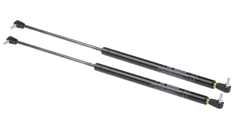

Gas Stay consists of a pressure tube and a piston rod with a piston as well as a valve that is actuated via the release pin. When the valve is opened, the extension force aids the user in adjusting his or her application in that the gas stay bears a large part of the weight force.
TOOLING DIRECTION
Tooling Direction created using bisecting line method from three point centre of the backdoor.
DRAFT ANALYSIS
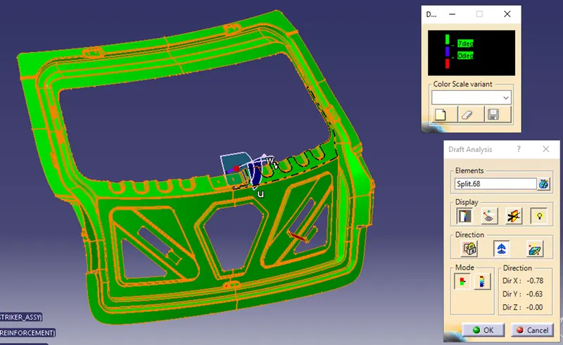
The Draft Analysis command allows us to detect if the part we drafted will be easily removed. This type of analysis is performed based on color ranges identifying zones on the analysed element where the deviation from the draft direction at any point, corresponds to specified values.
FINAL OUTPUT