Project 1
AIM:
In order to perform a Structural Analysis with the given CAD Geometry (IP - SUBSTRATE) by using ANSA. The process involved as follows
- Importing CAD Geometry into ANSA
- Topology Operation
- Performing Geometry Cleanup
- Mid-surface Extraction (Manually) and EXTENDING the RIBS, BUTTONS & CLIPS
- Applying given Quality Criteria - Presentation Parameters and Meshing Parameters
- Mesh Generation
- Checking the model for Quality Criteria
PROCEDURE:
Import the CAD Geometry into ANSA
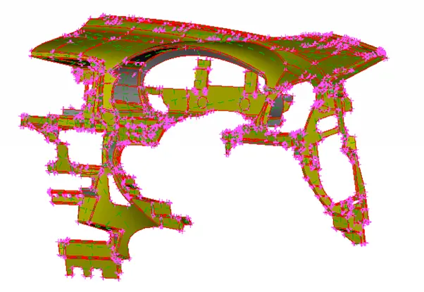
TOPOLOGY OPERATION
The Topology is used to recover the results of (Hot Points – Release) and (CONS – Release) functions. It is also used to recover the Topological conditions of a Face that was undeleted by the (Faces – Undelete) function.
Before doing Topo, Let us refine the Geometry with perimeters length. To do so, Go to MESH - Modules > Perimeters > Length. Now Length perimeter pop-up appears. Window select the whole Geometry and middle mouse click to set perimeters length of 1mm. Do the same for the Macros. Now we can see that the model is refined.
Do a Topo for the Geometry by Modules > Faces > Topo. Window select the whole model and Middle mouse click will do the operation.
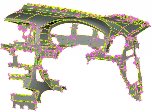
GEOMETRY CLEANUP
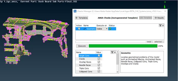
Geometry cleanup is done in order to get a better Mesh flow. To do so, Go to Checks Manager > Geometry.
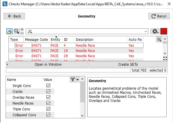
Now we can see on the Geometry check pop-up that ANSA is showing some errors on the CAD Geometry. The errors are Single CONS, Triple CONS, Needle Faces, unchecked faces and Cracks between CONS. In order to solve the error we have to select the set of each errors individually and right mouse click > show only. ANSA would show only the error areas. To find where exactly you have the error, Go to Neighbor > 1st level will bring the area visible. Then we can fix it manually.
MID-SURFACE EXTRACTION & EXTENSION
Now the CAD Geometry is ready to take Mid-surface. Before taking Mid-surface we have to measure the thickness on the edge perimeters of the Instrumental Panel. The measured value is 0.60mm. The offset value is 0.3
In order to do OFFSET – Go to TOPO > Modules Button > FACES > OFFSET then FEATURE AREA SELECTION. Also TURN ON Cross Hatches. Now select the middle surface of the Geometry and middle mouse click to take an offset. An Offset value pop-up appears. Set the Offset value of 0.3. Since the Offset direction is on Z Axis we give the value as -0.3 to get the offset exactly to the middle of the Geometry. And hit OK.
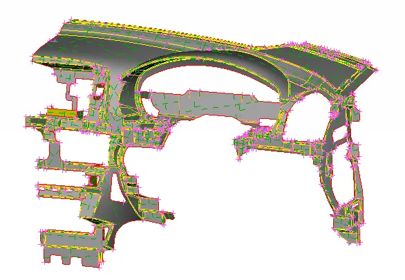
We have the MID for the IP. The below image represents the MID-Surface.
Next, we have to offset the RIBS and Buttons of the IP. Here the BUTTONS is a hollow part which doesn’t have any thickness. So we assume the thickness as 1 and so the offset value will be 0.5 in order to have the exact representation of the CAD. Then we measure the RIBS thickness by creating weld spots and offset them. To do so. Go to TOPO > Module Buttons > Hot points > WELD SPOT. Then multi project the weld spots created one side on all RIBs surface. Then measure the thickness. We can note down or store the thickness.
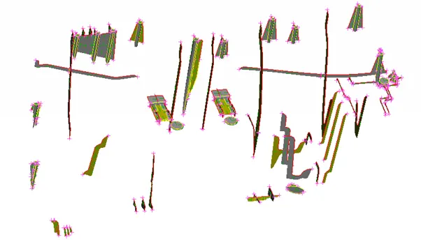
MID of BUTTONS, RIBS and CLIPS.
Now, we have to extend all the BUTTONS, RIBS and CLIPS. To do so. Go to TOPO > Modules Button > FACES > EXTEND. This function extends Faces according to a specific distance or until they reach a target Face or target group of Faces, by adding new Faces as extensions to the source ones. The new Faces Surfaces are extensions of the Surfaces of the sources. After which forms TRIPLE CONS.
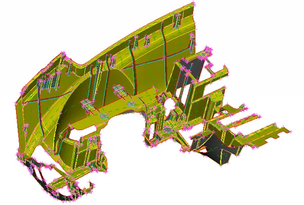
The above Fig. represents the EXTEND faces.
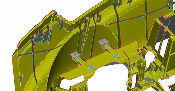
The below Fig. has a closer view of the same.
After Mid-surface extraction set separate PID (Property ID) for each Mid-surface extracted. To do Modules - Faces > Set PID. A selection window pop-up appears. Faces/Shells checked. Window select the whole surface and do a middle mouse click. A Property Help pop-up appears. Go to New > PSHELL > Set a Name then click OK. New Property ID is created. In order to apply double click on the created PID. PID is successfully applied. Similarly create PID for each Mid-surface extracted. Also assign the thickness.
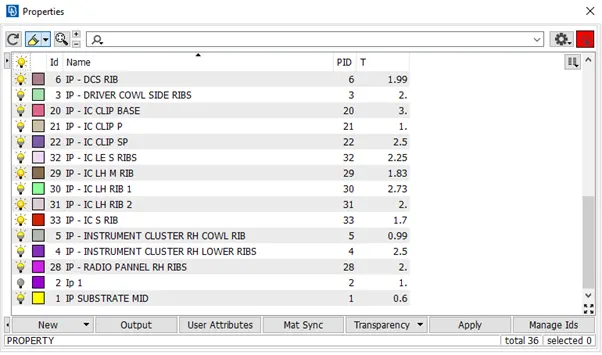
After Setting the PID. We have to do some surface cleanup. We might have some unwanted construction lines throughout the Surface to be eliminated. By eliminating unwanted construction lines and capturing the fillet areas in a proper way will lead us to Good MESH flow. Find which of the construction lines are not necessary and create construction lines wherever required. Most challenging part was capturing the Fillet region. To overcome the challenge of capturing the Fillet I used a set of commands. In order to remove the unwanted construction lines Go to TOPO - Modules > Faces > Cut. Right mouse click on the construction lines to remove it. If we unknowingly removed a construction line which is required, to bring it back TOPO - Modules > CONS > Release. Even if we remove the lines from the surface there will be a reference line of the lost line. Now select the line (CONS) middle mouse click. The CONS will be released and forms a SINGLE CONS. Then we have to do a Topology to connect the CONS. TOPO - Modules > Faces > Topo. Box select and do a Topo on the CONS which forms Double CONS. Now we regained the lost line. While removing and creating construction lines we might get some unwanted hot points. And there will be some unwanted hot points in the edges too. To remove those hot points. Go to TOPO - Modules > Hot points > Delete. To delete do a box selection with left mouse click on the hot point. On Narrow fillet areas the middle construction lines were captured by TOPO - Modules > Dach > Divide Face. This command was used to create a middle construction line. All lines are rearranged according to minimum length Quality Criteria. Which will result in best MESH flow. Now Surface is ready for Meshing.
MESH GENERATION AND QUALITY
To start with the MESHING process we have to set the given Quality Criteria
|
S.No |
Quality Criteria |
Value |
|
1 |
Target/Average length |
4 |
|
2 |
Minimum Length |
2 |
|
3 |
Maximum Length |
6 |
|
4 |
Aspect |
3 |
|
5 |
Warpage |
15 |
|
6 |
Skewness |
45 |
|
7 |
Jacobian |
0.7 |
|
8 |
Minimum Quad Angle |
45 |
|
9 |
Maximum Quad Angle |
135 |
|
10 |
Minimum Tria Angle |
30 |
|
11 |
Maximum Tria Angle |
120 |
|
10 |
Tria Percentage |
15 |
To do so, Press F11 in the Keyboard. A Quality Criteria - Presentation Parameter Pop-up appears. Set the above given values.
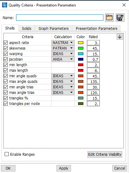
In the Presentation Parameters - Enable Elements % and and slide the Detail on demand effect slider to the (all details). Then hit APPLY then OK.
Next Open the MESH PARAMETERS in Utilities TAB. Then feed in the (Basic)
Mesh - GENERAL
Mixed Type – MIXED (Consist of Quad and Tria elements)
Order of Mesh – 1ST ORDER
Then we have to add our Target length of the mesh flow as 2mm. And set the Min. Target Length as 4mm and Max Target Length as 6mm. Then hit ok.
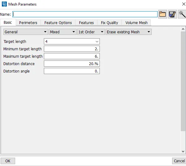
Now, we start with the Meshing process.
Go to MESH - Mesh Generation > Spot Mesh
The Spot Mesh algorithm gives better results than the free meshing method and creates the optimum number of shell elements, taking into account the element type already selected and the defined meshing parameters.
To solve the Quality issues we have to use RECONSTRUCTION command from SHELL MESH module. RECONSTRUCTION creates high quality surface MESH and solves the quality failed areas with high quality mesh flow according to the Values set in Quality Criteria and Mesh Parameters. After a reconstruction SMOOTH command is used to refine the mesh construction. SMOOTH command uniforms the mesh generation without changing the mesh orientation. Some areas we have to use SPLIT and SWAP command from Elements module in order to eliminate, split/swap or move the Tria element. With SPLIT command The Tria elements can be eliminated and arranged with directional flow of the neighboring Tria elements. With SWAP command such as Opposite Trias, Back to back Trias are separated. The Trias can be either swapped to left or right direction of the Mesh flow. Even the SPLIT command help in solving Opposite Trias, Back to back Trias in some areas. I also eliminated most of the possible Trias from the FE. I rearranged the Trias falling on the Fillet area. I used PASTE command from Grids Module to rearrange/move a step back the falling Trias from the fillet region.
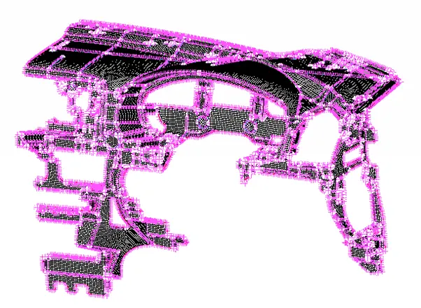
Now MESH Generation is completed. And the MESH is ready for FEA.
CONCLUSION
- Geometry Cleanup is done by fixture Unchecked faces and Needle faces Errors.
- PERIMETERS and MACROS are set to 5mm for refined edges.
- Mid-surface Extraction and Extension is done.
- Surface cleanup done for better MESH flow.
- Given Quality Criteria - Presentation Parameters and Meshing Parameters applied
- Mesh generated.
- Checked the model for Quality Criteria and Quality issues were solved.