Foundation Design using SAFE
1. Isolated footing Design using SAFE
1.1 Aim of the challenge- To model the isolated footing by using SAFE software and design the size, depth and steel provided as per IS 2911 (part-2) and IS sp- 34-1987 and IS 456:2000 and to drafting the detail reinforcement detailing of isolated footing using AUTOCAD.
1.2 Introduction
Given data,
Square footing of column size 400×400 mm
Compressive axial load combination of (1.5DL+1.5 LL) is 2000kN
Safe soil bearing capacity is 150kN/m2 at a depth of 2m below the ground level.
Assuming concrete grade of M25 and steel grade of Fe500.
1.2.1 Data required for SAFE analysis and design,
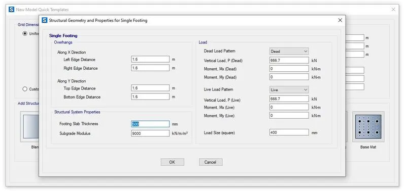
Un-factored load =2000/1.5= 1333.33kN
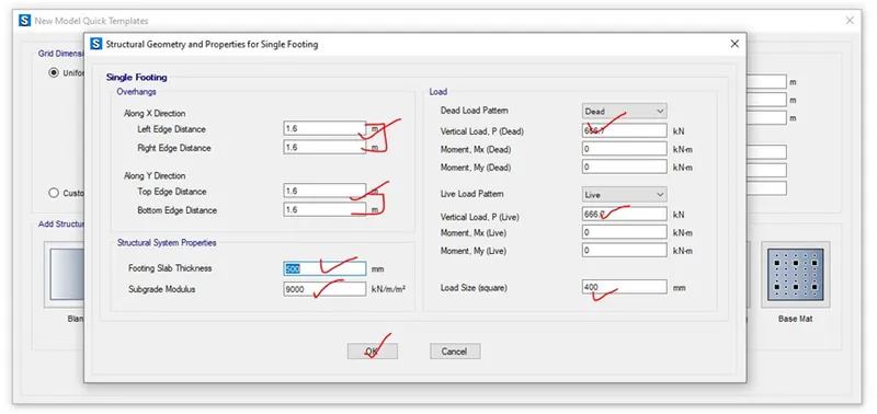
Assuming dead load is half of the un-factored load i.e. DL= 1333.3kN/2= 666.7kN
Assuming live load is half of the un-factored load i.e. LL= 1333.3kN/2= 666.7kN
Subgrade modulus for soil= safe bearing capacity ×(factor to ultimate/ maximum settlement)= 150×(3/0.05)= 9000kN/m3
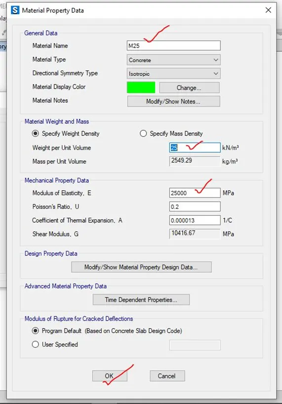
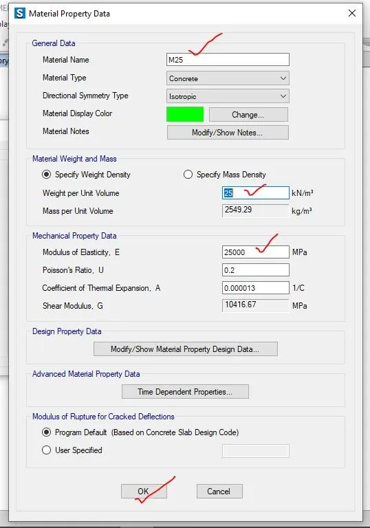
Elastic modulus of M25 concrete= 25000 N/mm2
1.3 Procedure in modelling of isolated footing-
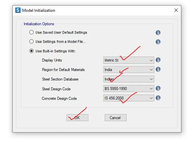
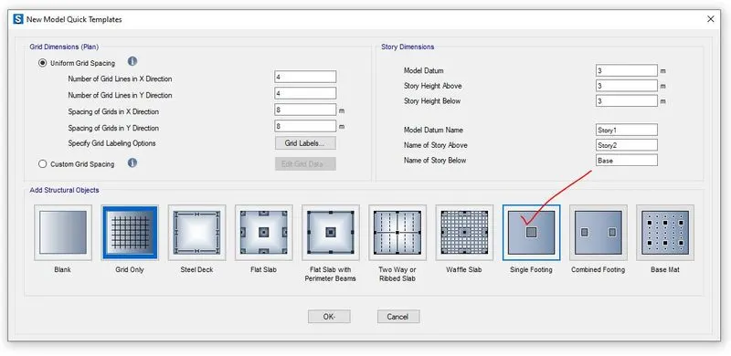
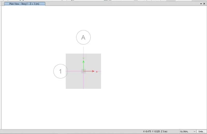
Step-1- After calculation of the required data for SAFE analysis and design i.e. Dead load, live load, subgrade modulus of soil from the given data, the SAFE software has been opened and new model has been created that is given below,
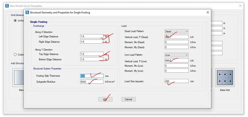
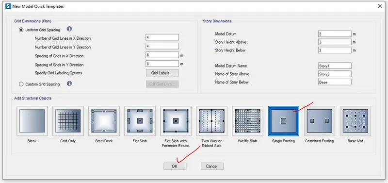
Step-2- For isolated footing, a new model quick templates where single footing has been chosen and structural geometry and properties for single footing has been required as per the project requirement i.e. given below,
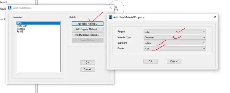
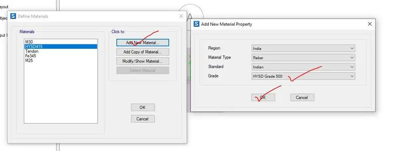
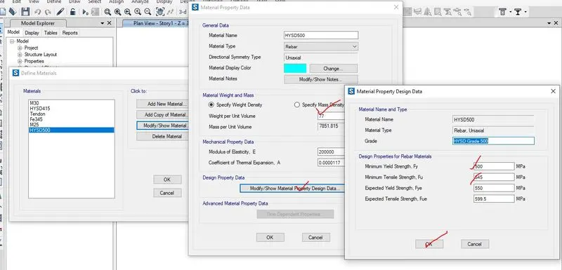
Step-3- In this step, the material properties of the concrete i.e. M25 and different reinforcement as steel i.e. Fe415 and Fe500 has been added, that has been shown below,
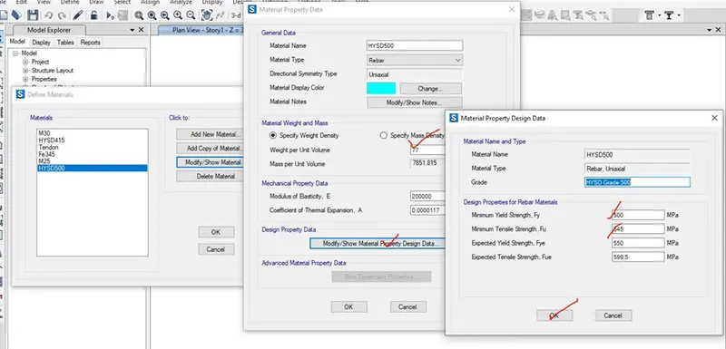
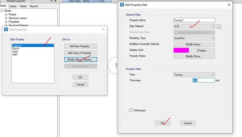
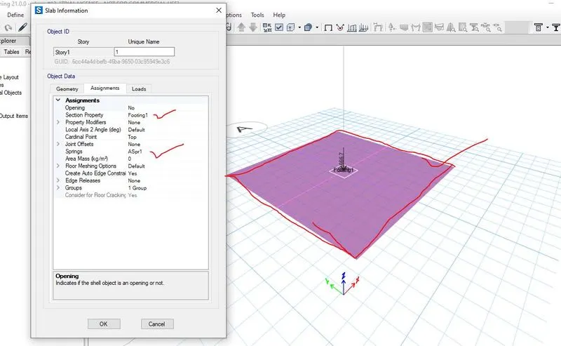
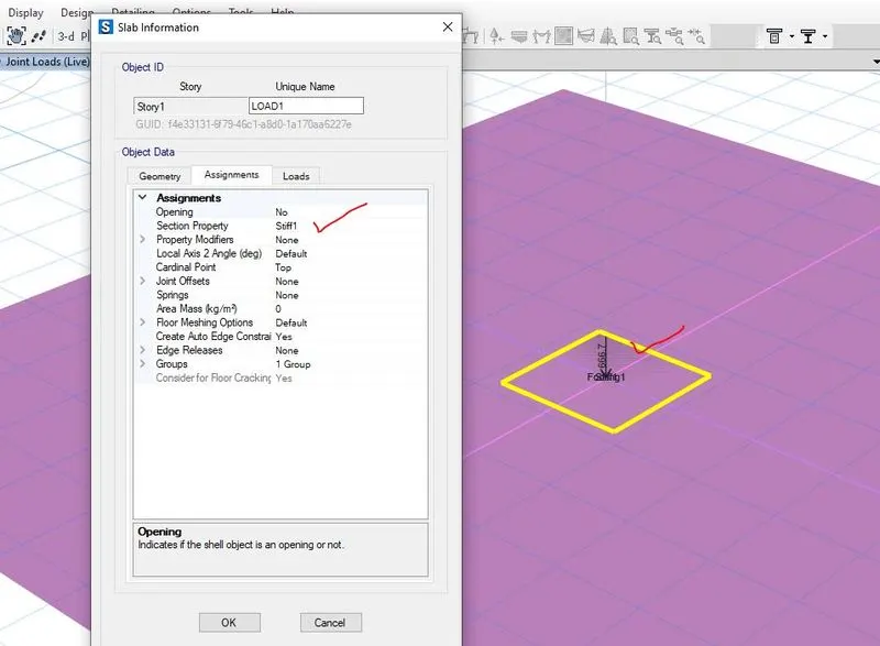
Step-4- After addition of material properties of concrete and rebar, the slab properties has been added where two slab has been added as foundation as footing type and stiff slab for column base as stiff property data.
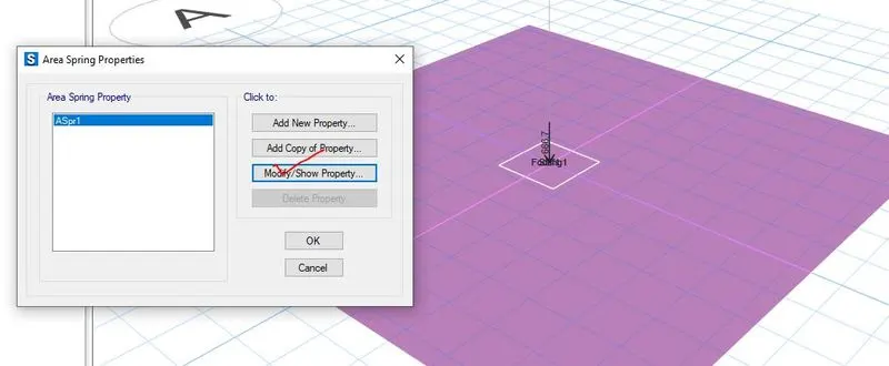
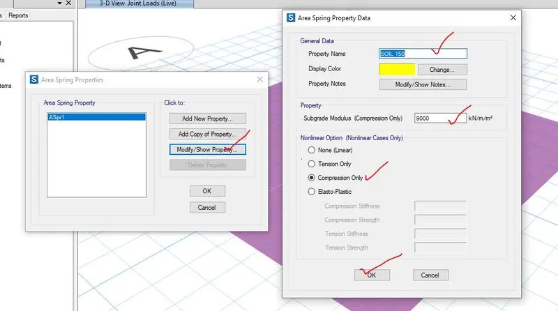
Step-5- For soil properties, subgrade modulus of soil for isolated footing has been added as area spring properties to the soil and here, subgrade modulus of soil (k) is 9000kN/m3 which has been calculated above.
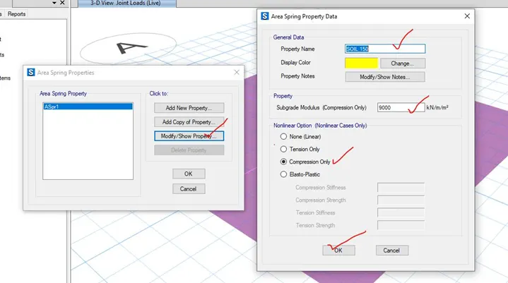
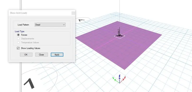
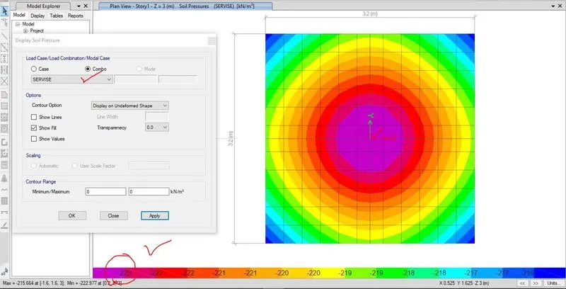
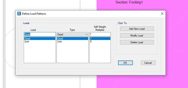
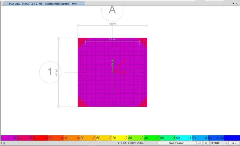
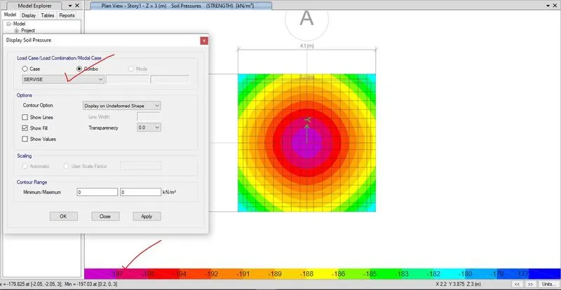
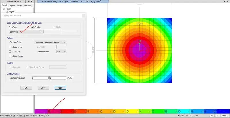
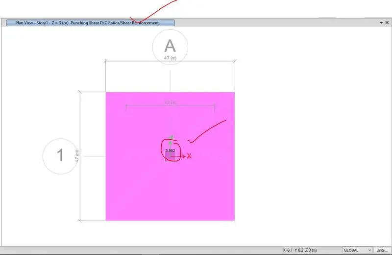
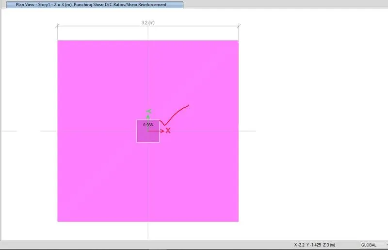
Step-6- In this step, different load pattern i.e. dead load and live load has been added and load combination has been created for serviceability and strength criteria and the footing model has been analysed and checked for shear failure and soil bearing capacity.
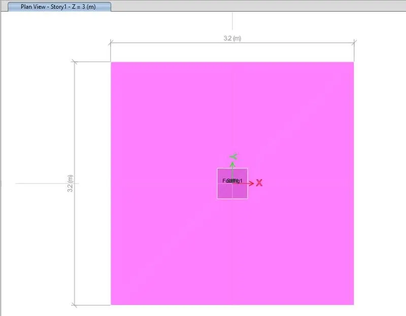
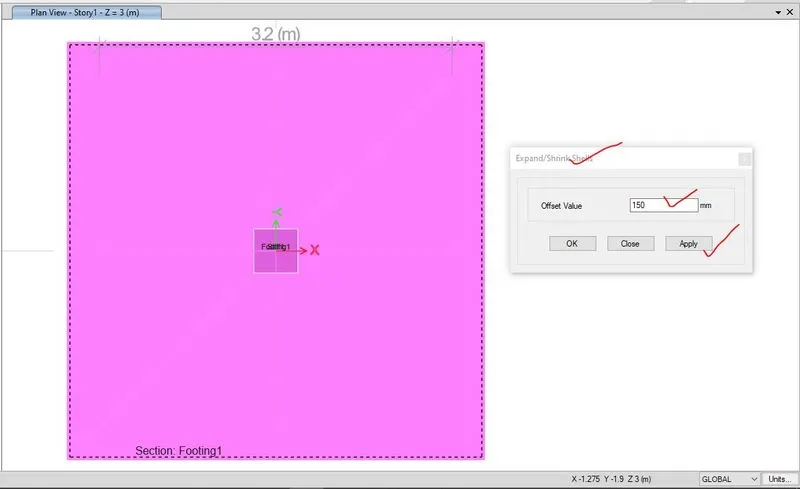
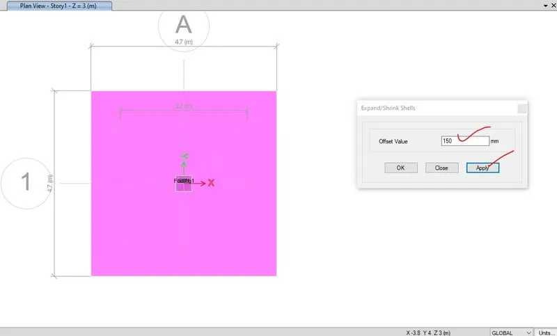
In this project, as this model has been failed due to bearing so the area has been increased.
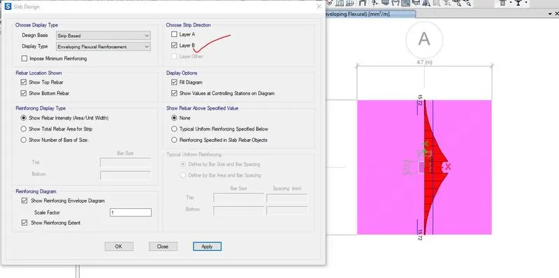
Step-7- After ensuring the shear check and bearing check, then this footing model has been designed. For designing, first of all design strips of both the direction has been created. In this isolated footing for both the direction, strip has been created though out the width.
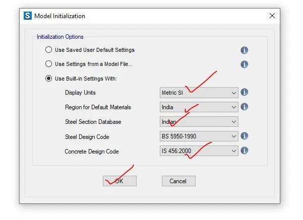
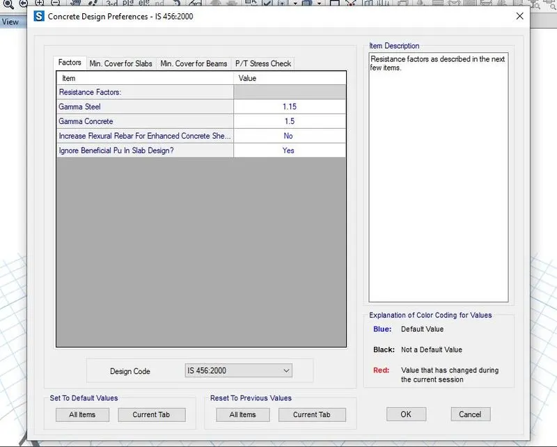
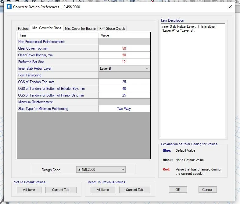
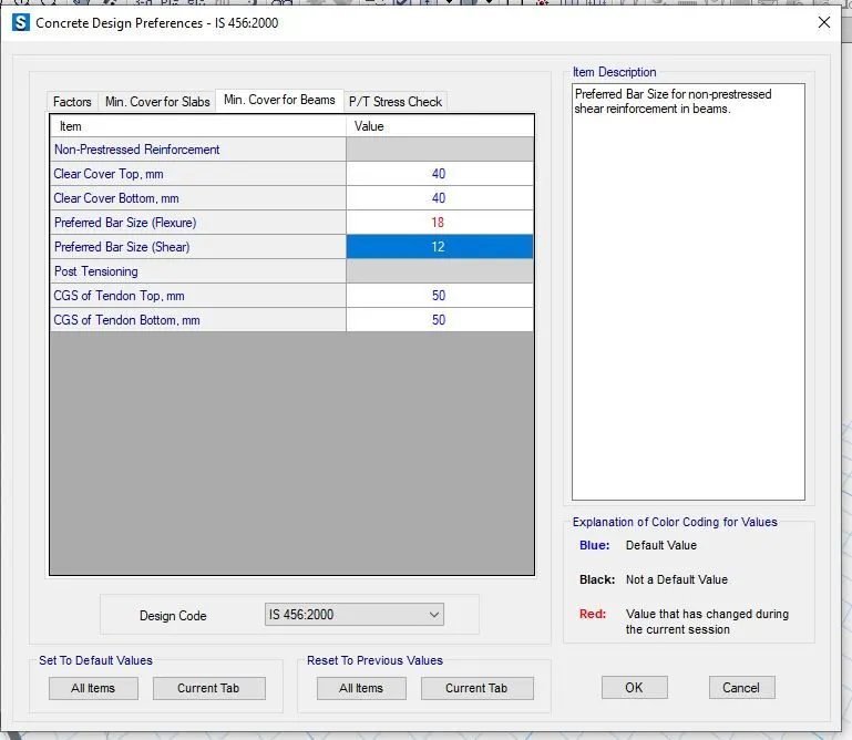
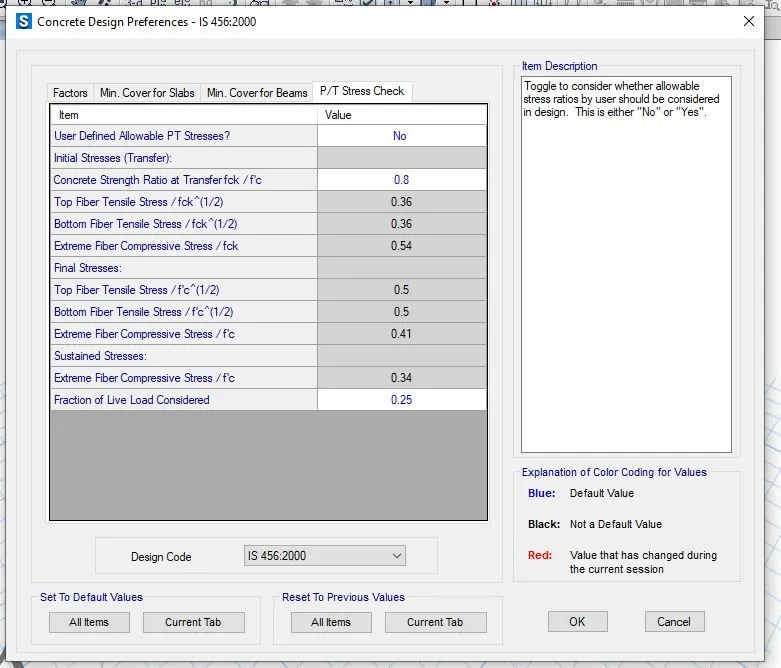
Step-8- Then concrete design preference as per IS 456-2000 before designing which has been shown below. After providing the design preference, the footing model has been designed and maximum moment and area per unit width for both strip has been checked.
For strip layer A, area of steel per unit width= 1644.54mm2
For strip layer B, area of steel per unit width= 1717.8 mm2
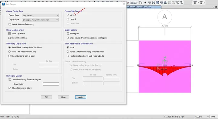
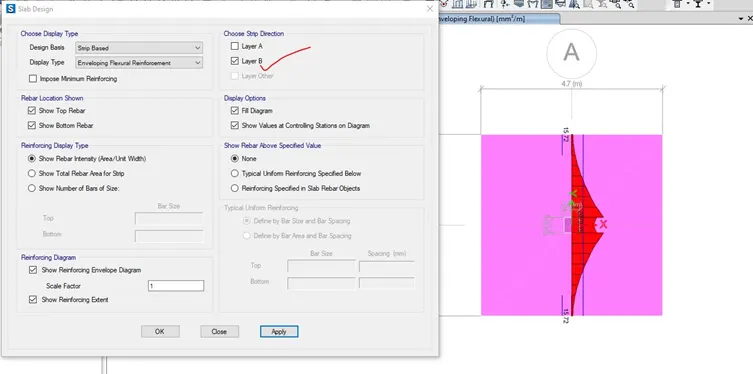
Step-9- After finding of the area of steel, no of bars with proper size and spacing for both the strip in x and y direction, reinforcement detailing has been drafted in AUTOCAD.
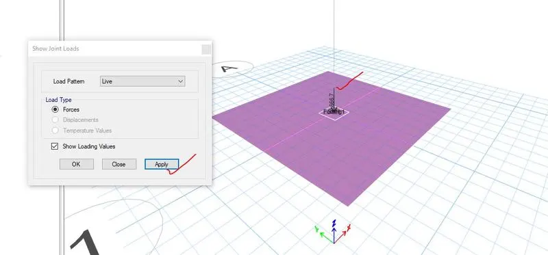
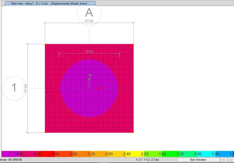
1.3.1 All the stepwise screenshots in modelling, analysis and design of isolated footing


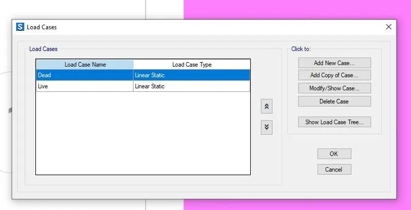
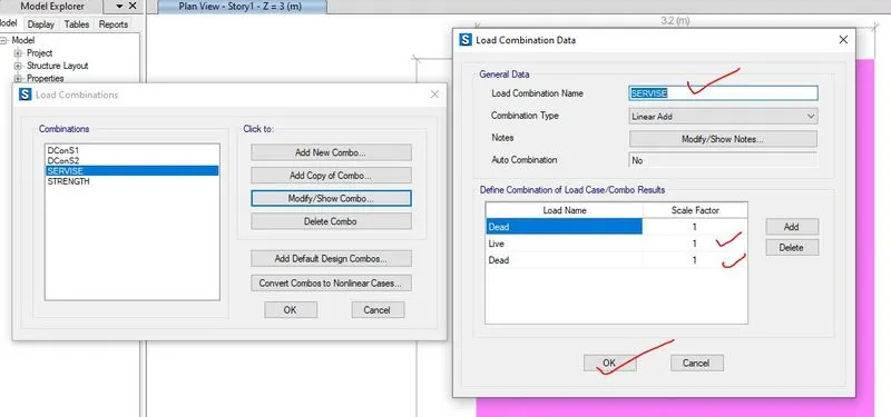
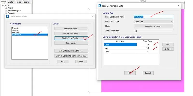
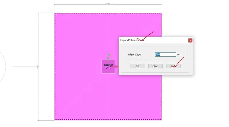
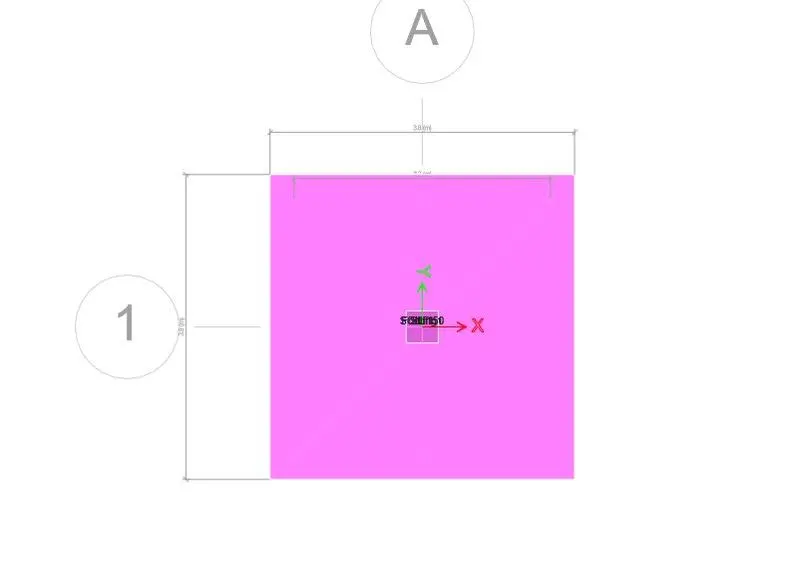

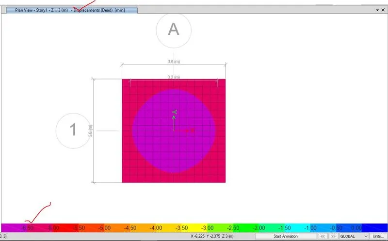
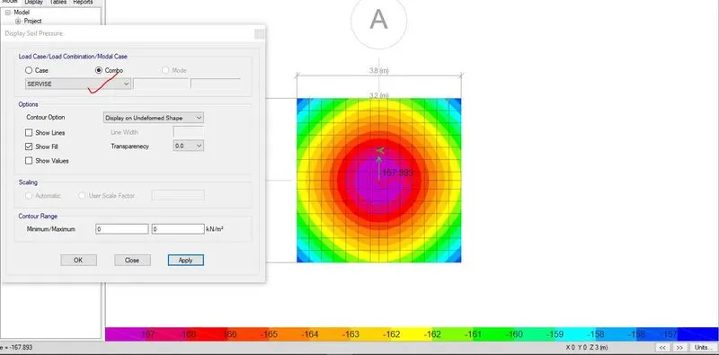
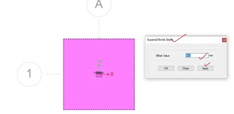
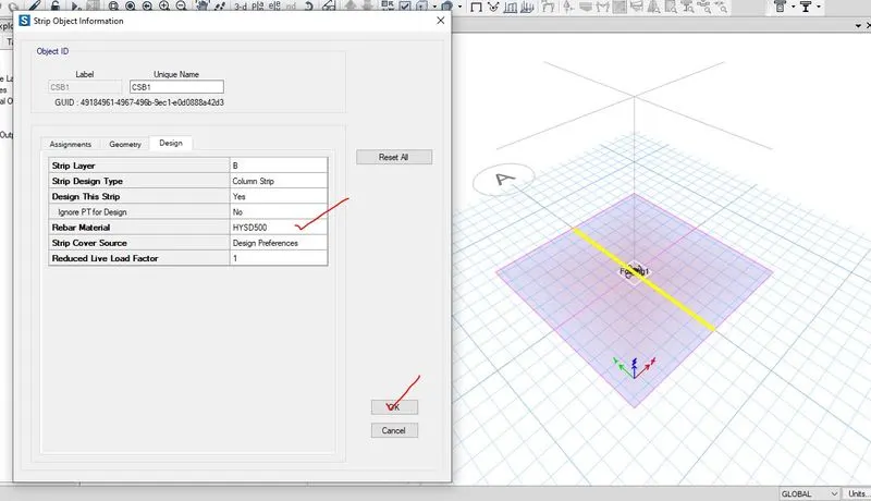
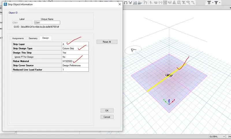
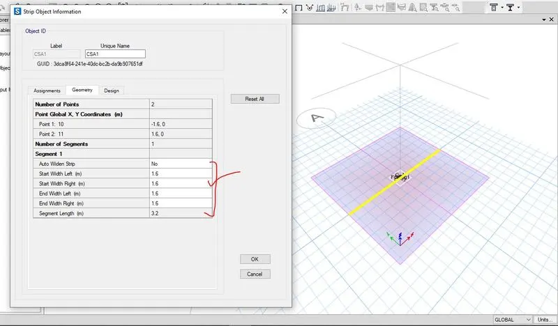
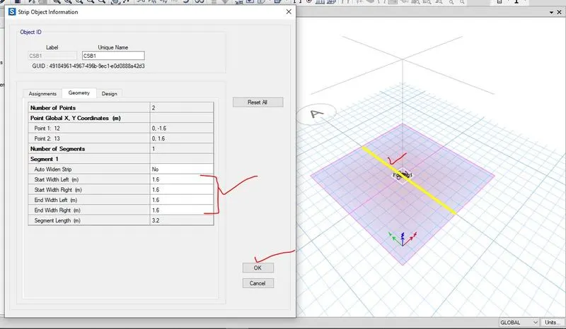
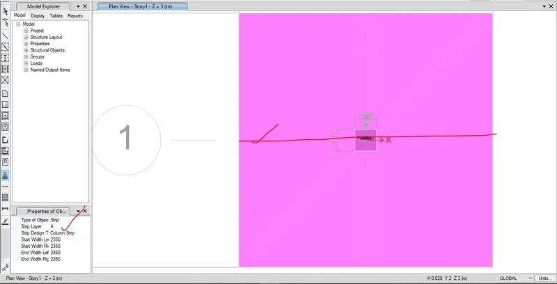
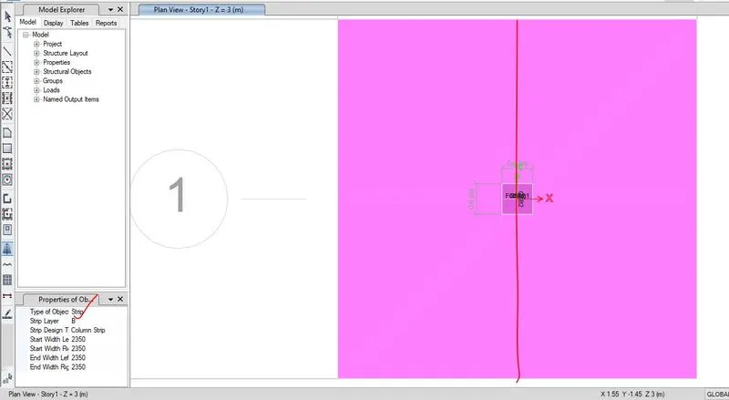
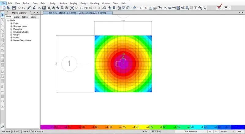
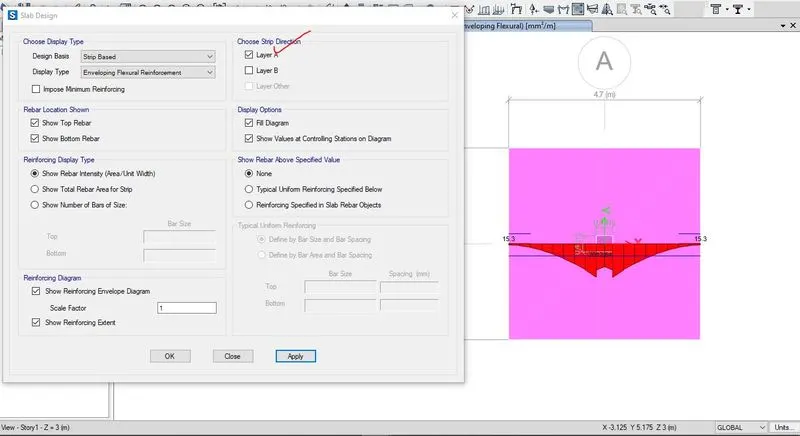
1.4 Results and discussion
1.4.1 Calculation of bar detailing for isolated footing
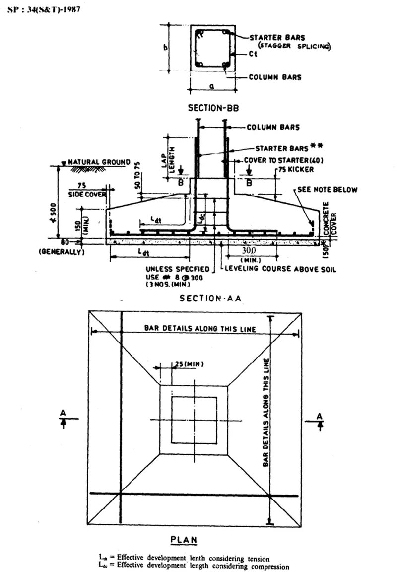
As per IS sp-34:1987, the detail reinforcement detailing of isolated footing has been given below,
For strip layer A-
Area of steel per unit width= 1644.54 mm2
Assuming 16mm diameter bar, the numbers of bars= (1644.54/ ((pie/4)×162))= 8.17 i.e. 9
Area of steel provided= 9× ( pie/4)×162= 1,809.56 mm2
Spacing can be calculated as,
Spacing= (1000/9)= 111.11mm, so provide 100mm spacing,
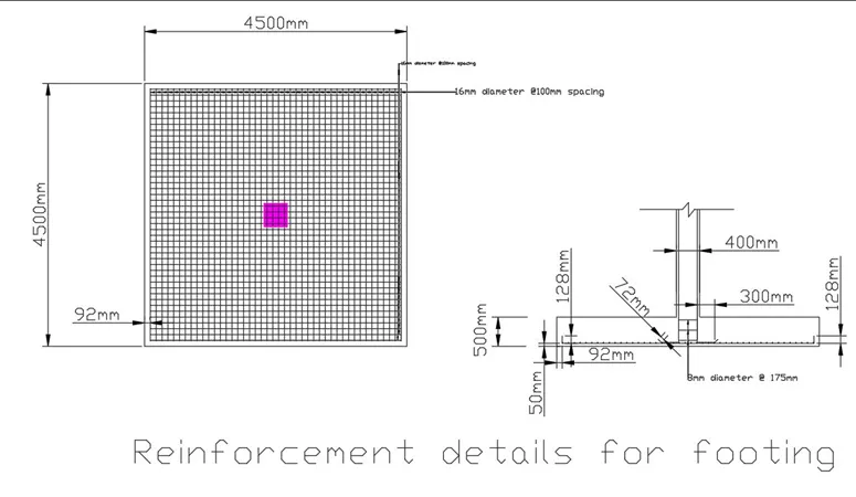
For strip layer A, provide 16mm diameter @100mm spacing.
For strip layer B-
Area of steel per unit width= 1717.8 mm2
Assuming 16mm diameter bar, the numbers of bars= (1717.8/ ((pie/4)×162))= 8.54 i.e. 9
Area of steel provided= 9× ( pie/4)×162= 1,809.56 mm2
Spacing can be calculated as,
Spacing= (1000/9)= 111.11mm, so provide 100mm spacing,
For strip layer B, provide 16mm diameter @100mm spacing.
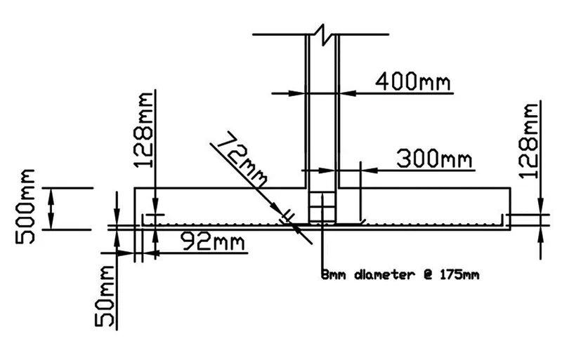
Reinforcement detailing of the isolated footing has been drafted by using AUTOCAD which is shown below,
NOTE-
The results of modelling, analysis and designing isolated footing by using SAFE i.e. the .fdb file named as “chng_#13_isolated_rough_2” and drafting file of AUTOCAD i.e. dwg file named as “isolated footing” have been uploaded below.
---------------------------------------------------------------------------------------------------------------------------
2.Pile cap Design using SAFE
2.1 Aim of the challenge-To model the pile foundation by using SAFE software and design the pile cap size, depth of pile cap and longitudinal steel provided as per IS 2911 (part-2) and IS sp- 34-1987 and IS 456:2000 and to drafting the detail reinforcement detailing of isolated footing using AUTOCAD.
2.2 Introduction
Given data,
Square footing of column size 600×600 mm
Compressive axial load combination of (DL+ LL) is 1175kN which is supported on the pile cap.
16 meters of pile length, having diameter of 500mm and each pile has load carrying capacity of 200kN
Safe soil bearing capacity is 150kN/m2 at a depth of 2m below the ground level.
Assuming concrete grade of M25 and steel grade of Fe500.
2.2.1 Data required for SAFE analysis and design,
Un-factored load =1175kN
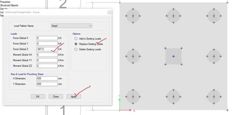
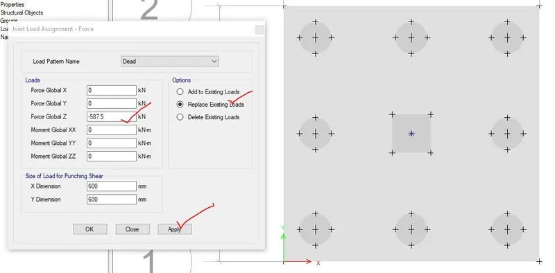
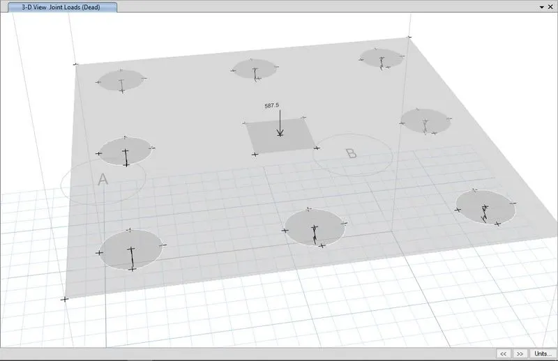
Assuming dead load is half of the un-factored load i.e. DL= 1175kN /2= 587.5kN
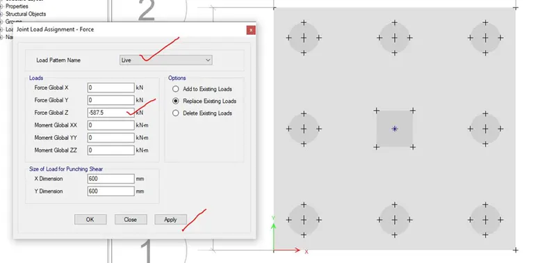
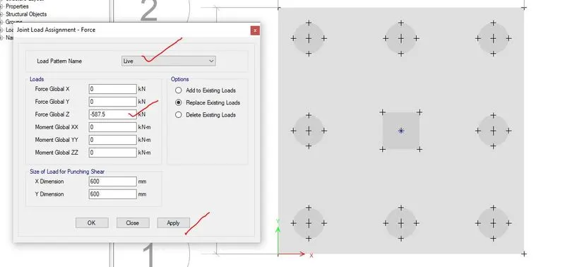
Assuming live load is half of the un-factored load i.e. LL= 1175kN /2= 587.5kN
Subgrade modulus for soil calculation,
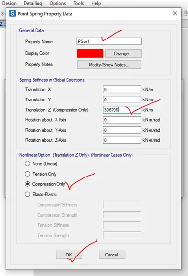
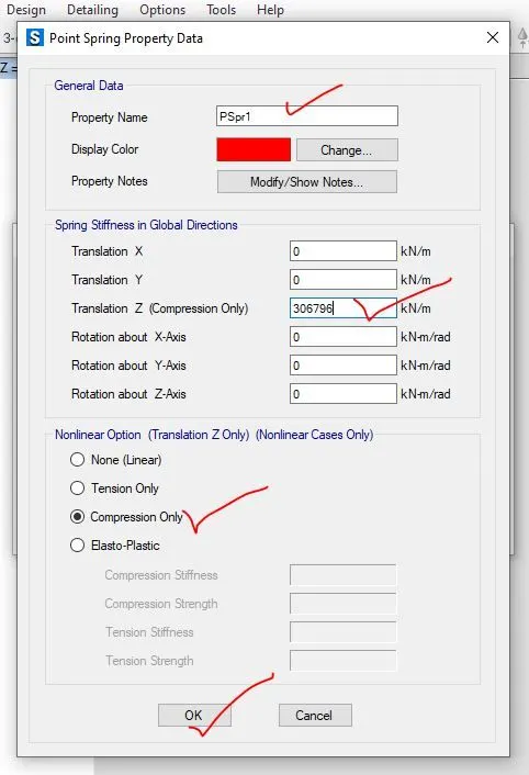
Point spring of pile = A ×E /L =196349×25000/16000=306796 kN/m
Point spring of pile =306.8 kN/mm
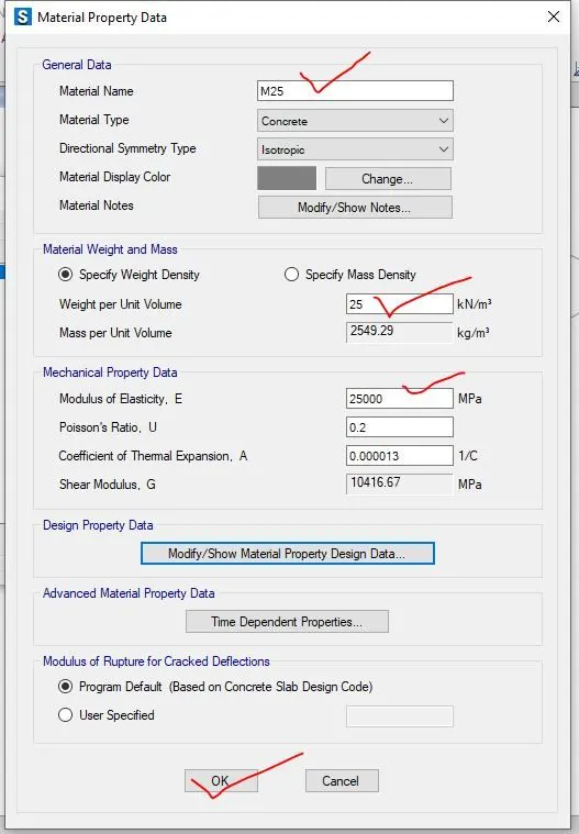
Elastic modulus of M25 concrete= 25000 N/mm2
2.3 Procedure in modelling of pile footing-
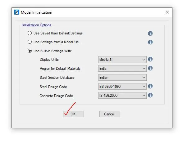
Step-1- After calculation of the required data for SAFE analysis and design i.e. Dead load, live load, subgrade modulus of soil from the given data, the SAFE software has been opened and new model has been created that is given below,
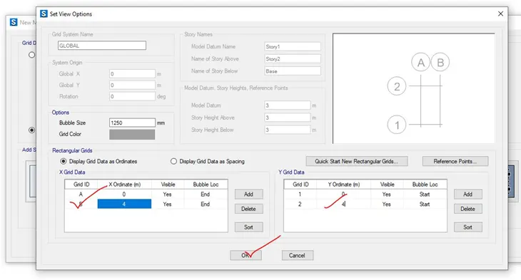
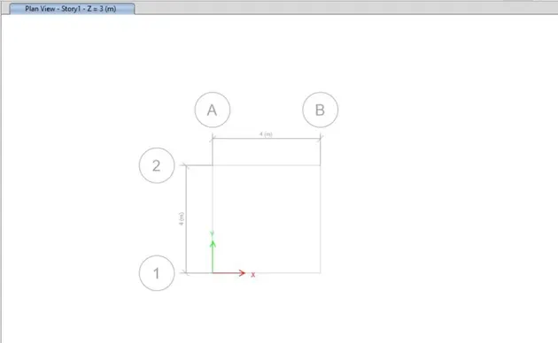
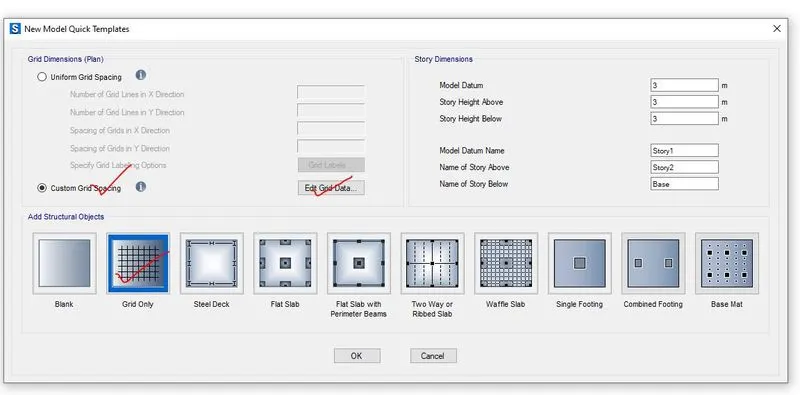
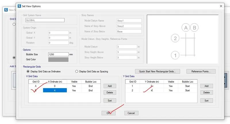
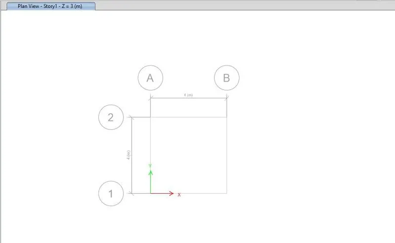
Step-2- For pile foundation, the grid pattern has been created and grid dada is added.
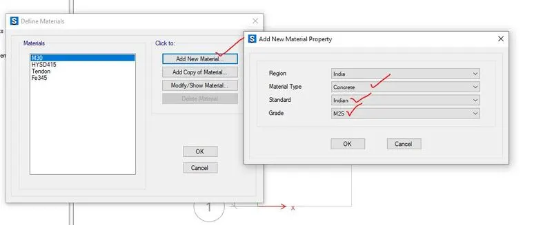
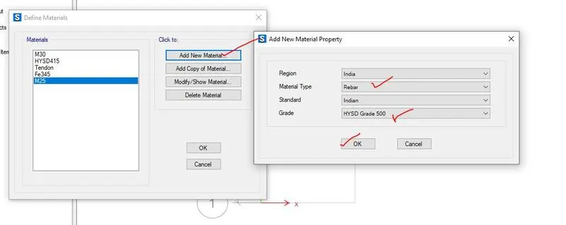
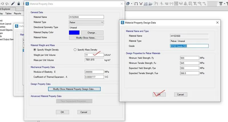
Step-3- In this step, the material properties of the concrete i.e. M25 and different reinforcement as steel i.e. Fe415 and Fe500 has been added, that has been shown below,
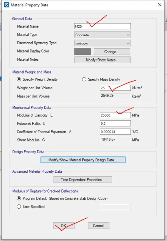
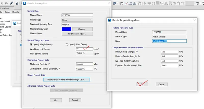
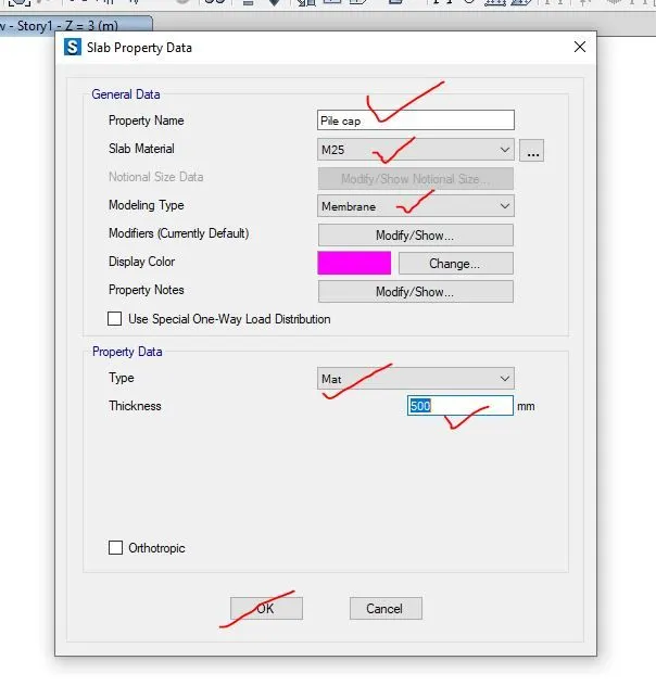
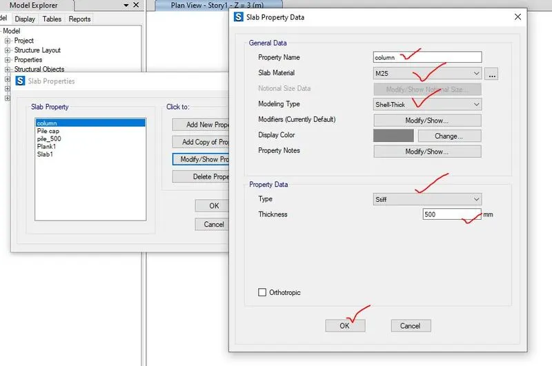
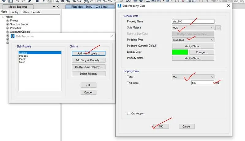
Step-4- After addition of material properties of concrete and rebar, the slab properties has been added where two slab has been added as pile cap as mat type, column as stiff type and pile_500 as mat type.
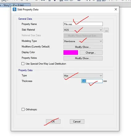
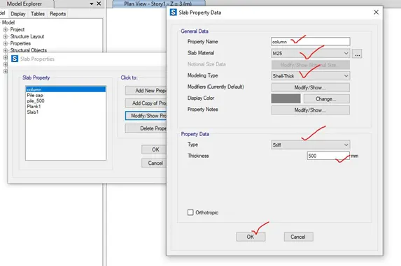
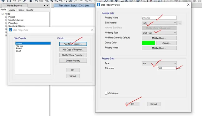
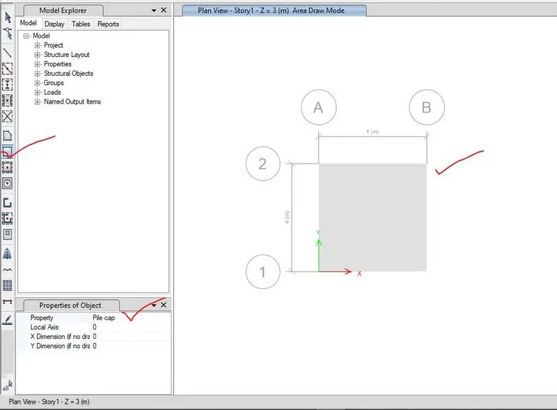
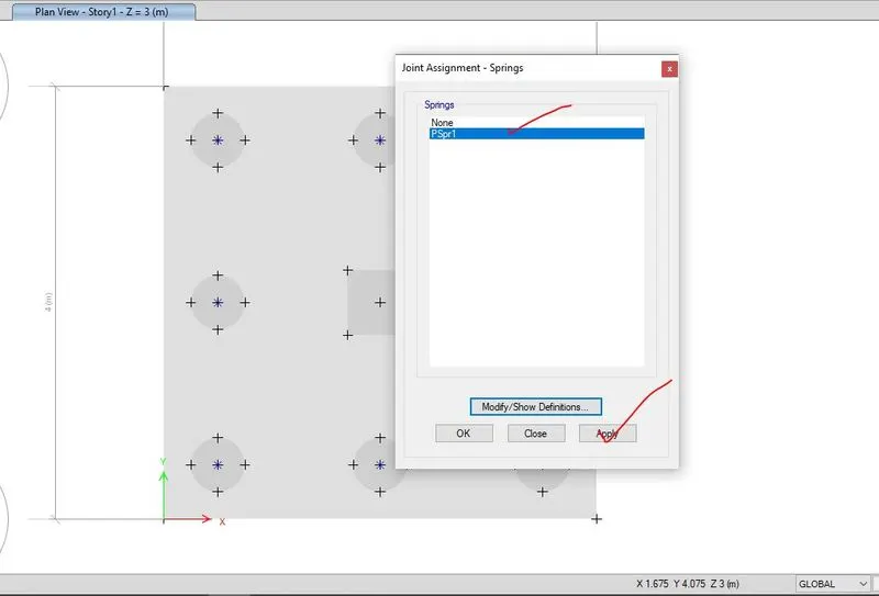
Step-5- the material has been assigned i.e. firstly pile cap has been assigned by using the quick draw slab properties. Now, to locate the pile below the pile cap, point object has been created so that pile can be placed in that required location and pile of 500mm diameter and column has been placed to appropriate place has been assigned to that point location.
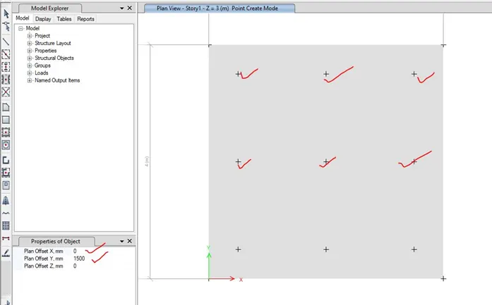
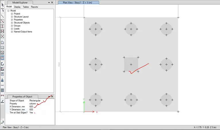
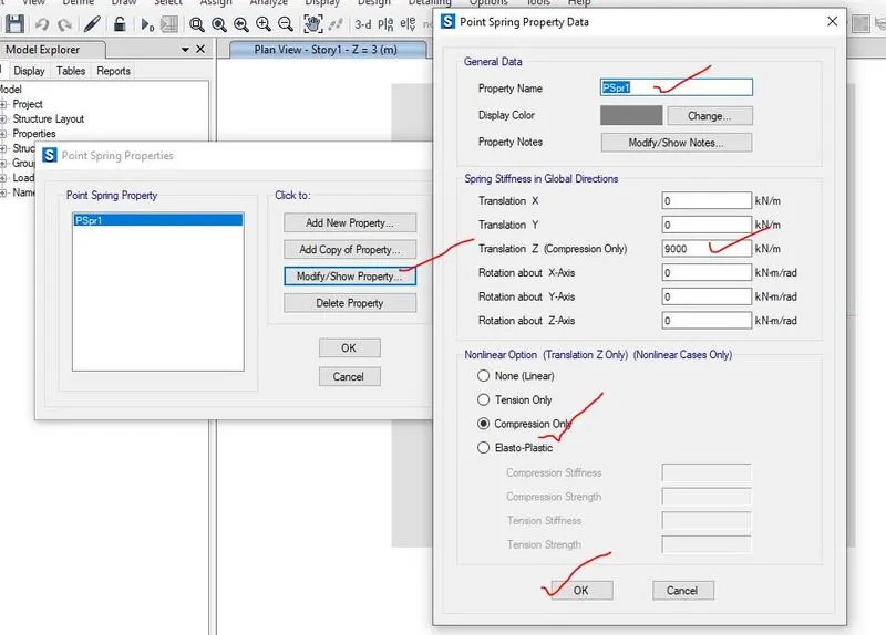
Step-6- For soil properties, subgrade modulus of soil for isolated footing has been added as point spring properties to the soil and here, subgrade modulus of soil (k) is 306796 kN/m which has been calculated above. This point spring properties has been assigned to the point object where pile is placed.
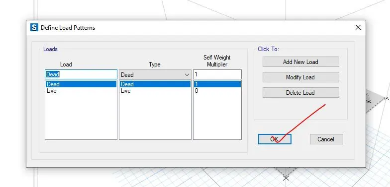
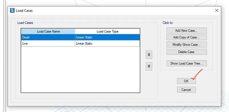
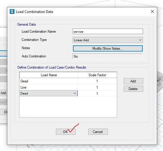
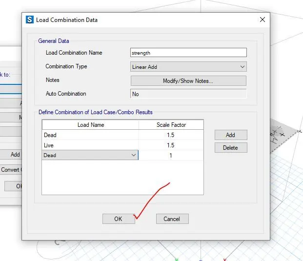
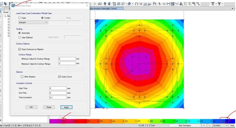
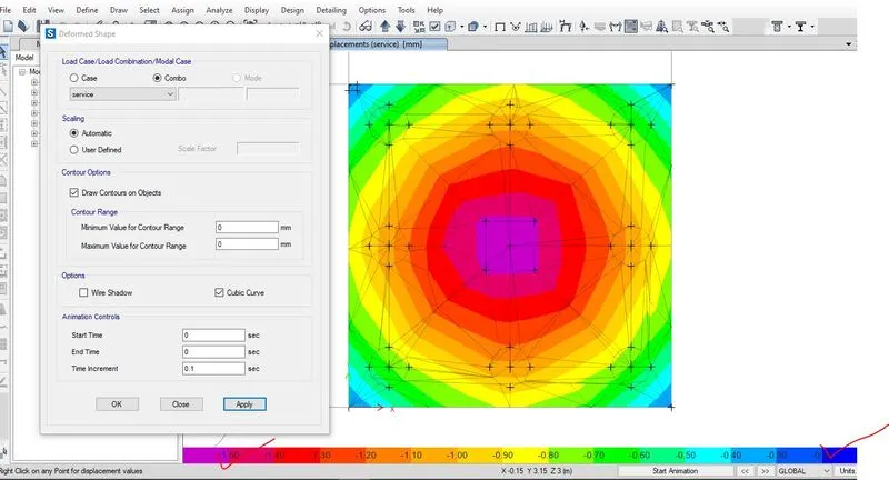
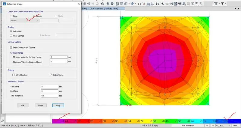
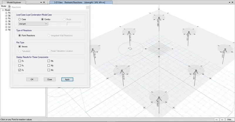
Step-7- In this step, different load pattern i.e. dead load and live load has been added and load combination has been created for serviceability and strength criteria and the footing model has been analysed and checked for shear failure and soil bearing capacity.
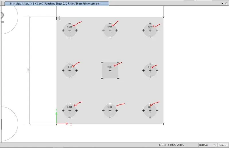
Step-8-After defining the load pattern, load has been assigned to the model where dead load is 587.5kN and live load is also 587.5kN and this model has been analysed by using the run bottom checked for shear failure and soil bearing capacity.
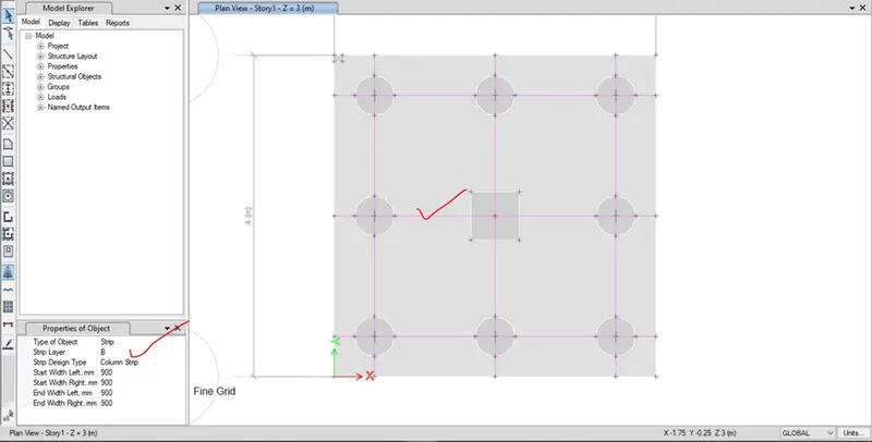
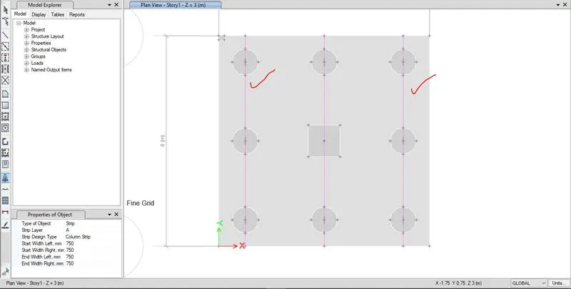
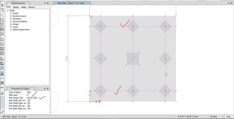
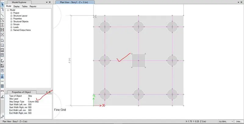
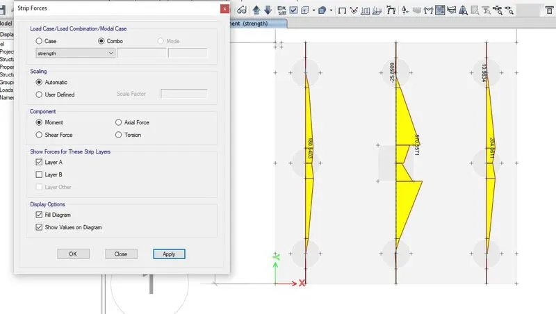
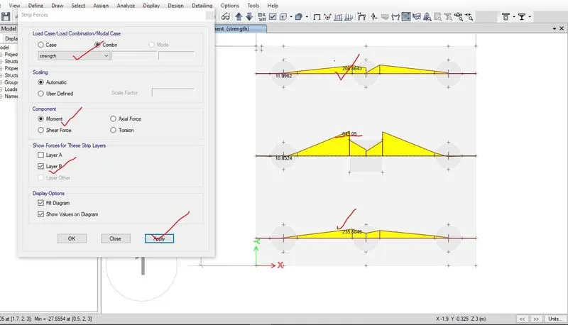
Step-9- After ensuring the shear check and bearing check, then the next step is design. For designing, first of all design strips of both the direction has been created. In this isolated footing for both the direction. For this model, three design strip for x direction i.e. one middle strip and two side strip and three design strip for y direction i.e. one middle strip and two side strip has been created i.e. given below,
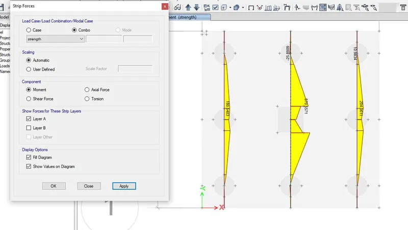
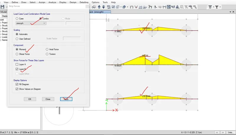
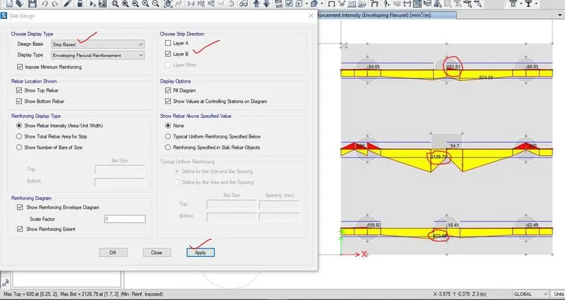
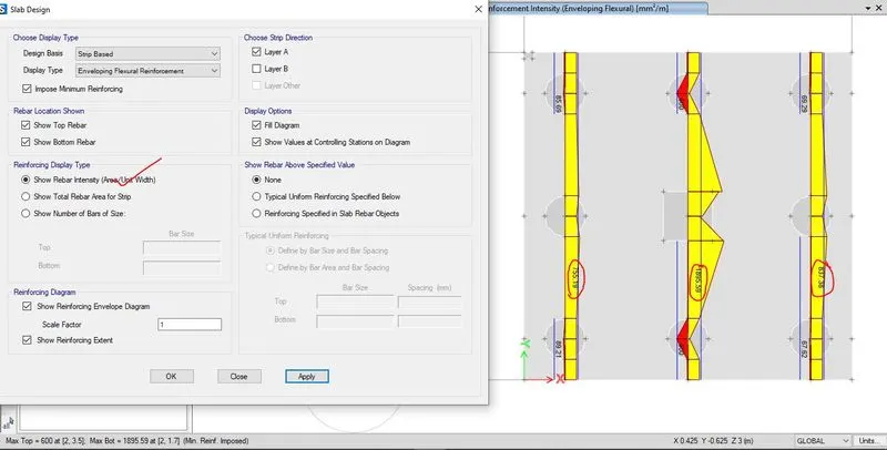
Step-10- Then concrete design preference as per IS 456-2000 before designing which has been shown below. After providing the design preference, the footing model has been designed and maximum moment and area per unit width for both strip has been checked.
For strip layer A, max area of steel per unit width for middle strip= 1843.64mm2
For strip layer A, max area of steel per unit width for side strip= 837.38mm2
For strip layer B, max area of steel per unit width for middle strip= 2128.7mm2
For strip layer B, max area of steel per unit width for side strip= 972mm2
For strip layer A, max moment for middle strip = 570.56mm2
For strip layer A, max moment for side strip= 204.06 mm2
For strip layer B, max moment for middle strip = 645.05mm2
For strip layer B, max moment for side strip= 235.88 mm2
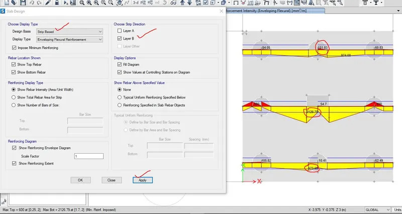

Step-10- After finding of the area of steel, no of bars with proper size and spacing for both the strip in x and y direction, reinforcement detailing has been drafted in AUTOCAD.
2.3.1 All the stepwise screenshots in modelling, analysis and design of pile cap of pile group
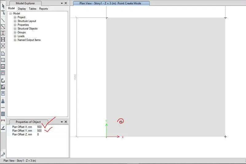
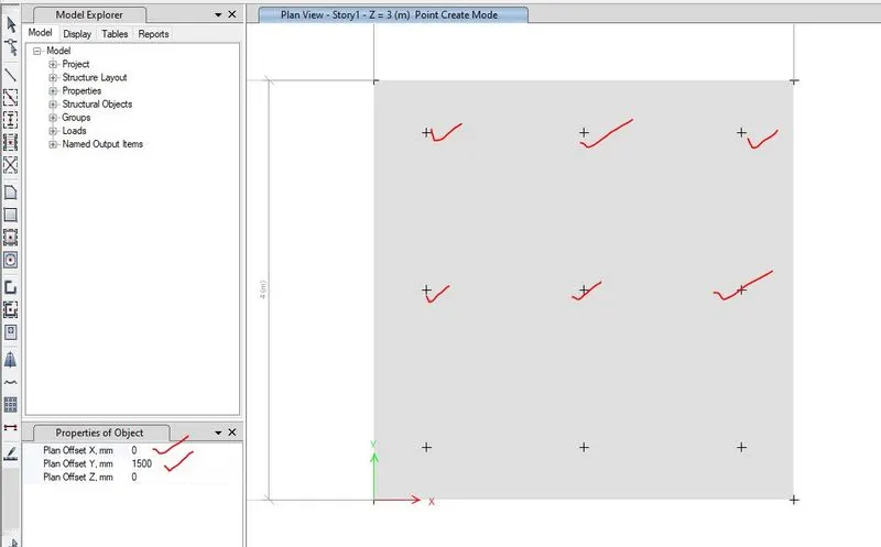
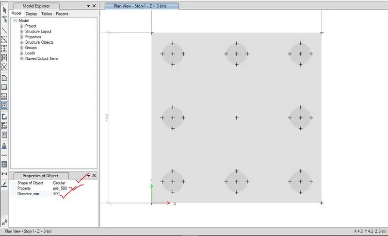
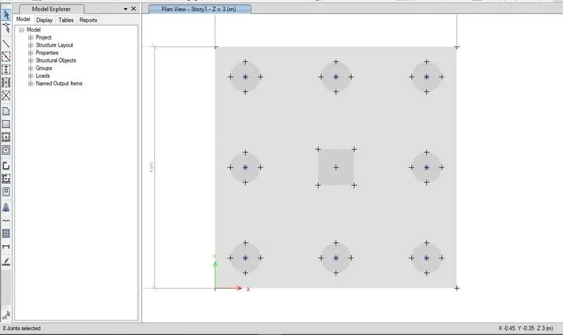
2.4 Results and discussion
2.4.1 Calculation of bar detailing for pile foundation
For middle strip layer A-
Area of steel per unit width= 1843.64 mm2 i.e. 1844 mm2
Assuming 16mm diameter bar, the numbers of bars= (1844/ ((pie/4)×162))= 9.17 i.e. 9
Area of steel provided= 9× ( pie/4)×162= 1,809.56 mm2
Spacing can be calculated as,
Spacing= (1000/9)= 111.11mm, so provide 100mm spacing,
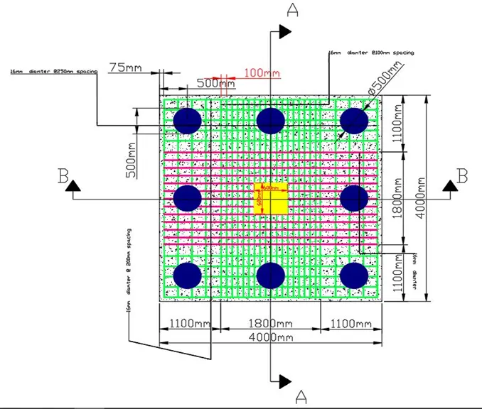
For middle strip layer A, provide 16mm diameter @100mm spacing.
For side strip layer A-
Area of steel per unit width= 837.38 mm2 i.e. 840 mm2
Assuming 16mm diameter bar, the numbers of bars= (840/ ((pie/4)×162))= 4.16 i.e. 4
Area of steel provided= 4× ( pie/4)×162= 804.24mm2
Spacing can be calculated as,
Spacing= (1000/4)= 250mm, so provide 250mm spacing,
For side strip layer A, provide 16mm diameter @250mm spacing.
For middle strip layer B-
Area of steel per unit width= 2128.7 mm2 i.e. 2130mm2
Assuming 20mm diameter bar, the numbers of bars= (2130/ ((pie/4)×202))= 6.7 i.e. 7
Area of steel provided= 7× ( pie/4)×202= 2,199.11 mm2
Spacing can be calculated as,
Spacing= (1000/7)= 142.85mm, so provide 150mm spacing,
For middle strip layer B, provide 20mm diameter @150mm spacing.
For side strip layer B-
Area of steel per unit width= 972 mm2
Assuming 16mm diameter bar, the numbers of bars= (972/ ((pie/4)×162))= 4.83 i.e. 5
Area of steel provided= 5× ( pie/4)×162= 1,005.30mm2
Spacing can be calculated as,
Spacing= (1000/5)= 200mm, so provide 200mm spacing,
For side strip layer B, provide 16mm diameter @200mm spacing.
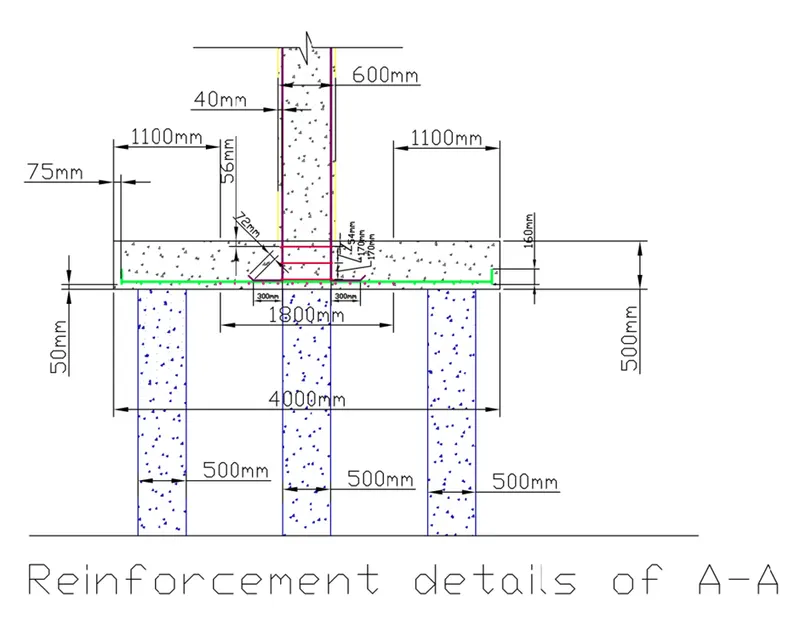
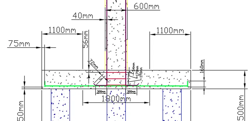
Reinforcement detailing of the isolated footing has been drafted by using AUTOCAD which is shown below,
NOTE-
The results of modelling, analysis and designing pile cap by using SAFE i.e. the .fdb file named as “chng_#13_pile_foundation_8” and drafting file of AUTOCAD i.e. dwg file named as “pile foundation” have been uploaded below.