Project 2_Design & Analysis of a Hostel building at Guwahati, Assam
1.1 Aim of the project- To experience the entire design process from modelling, analysis, design and preparation of construction drawings using AUTOCAD and ETABS of a G+3 RCC building (Hostel block in an academic institute) in Guwahati, Assam.
1.2 Introduction-
Necessary data of the building is given below,
- The walls will be made of AAC blocks.
- The buildings rests on type 3 soil. Piles of length 10 meters and 500 mm diameter with load carrying capacity of 280 KN is to be used.
- The ground floor level will be at a height of 2 meters above existing site level to avoid flood water enter the building.
- M25 grade of concrete with Fe500 for longitudinal reinforcement and Fe 415 for shear reinforcement is to be used.
- Floor plan of the Hostel block is given below,
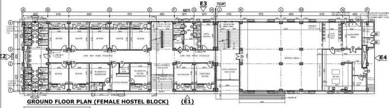
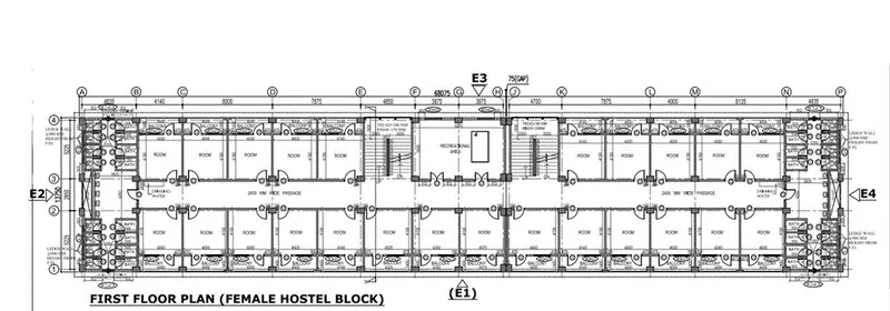
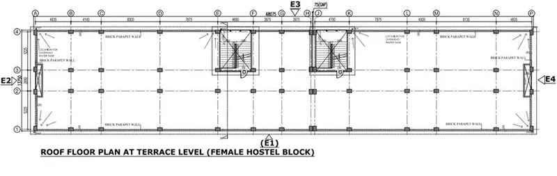
- Elevation of the hostel building
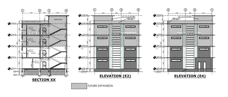
1.2.1 IS codes used in this project for reference:
- IS 875 part 1
- IS 875 part 2
- IS 13920
- IS 1893
- IS 2911 part 2
- IS 456
- SP 34
1.2.2 Data required for modelling and analysis of the building in ETABS
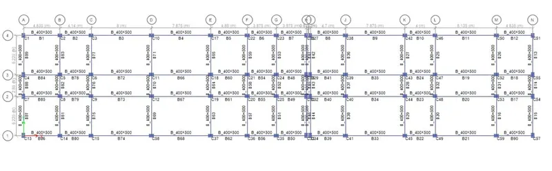
- Beam-column layout of the hostel block 1 and hostel block 2
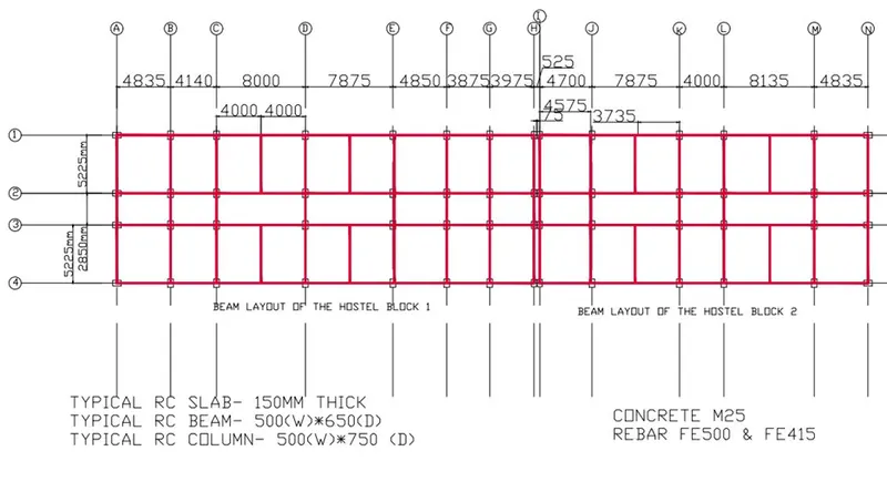
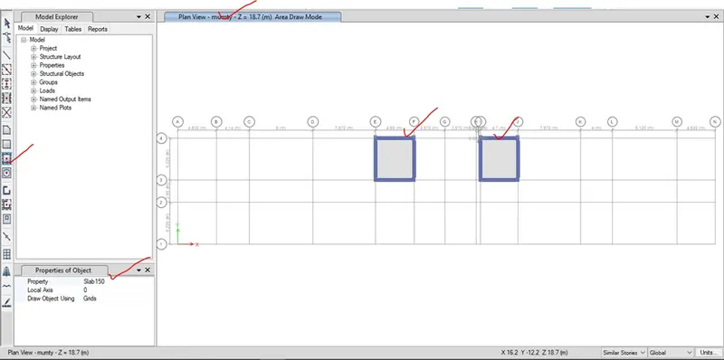
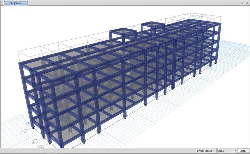
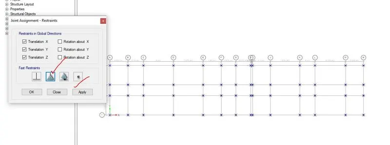
- Pinned support, Base+ 4 storey (ground to terrace)+ mumty.
- Column size is assumed as 500mm×750mm, beam size i.e. 500mm×650mm, slab of thickness 150mm.
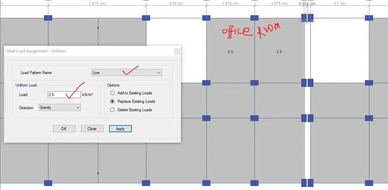
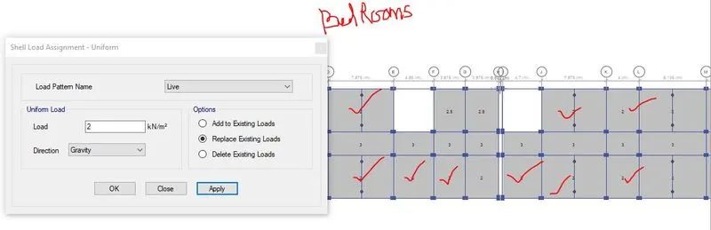
- Live load hostel building as per IS 875- part II,
- kitchen- 2kN/m
- Dining- 4kN/m
- Living room/ Bedroom-2kN/m
- Store room-5kN/m
- Office room-2.5 kN/m
- Toilet and bathroom-2 kN/m
- Balcony -2kN/m
- Corridor passage, staircase and store room-3 kN/m
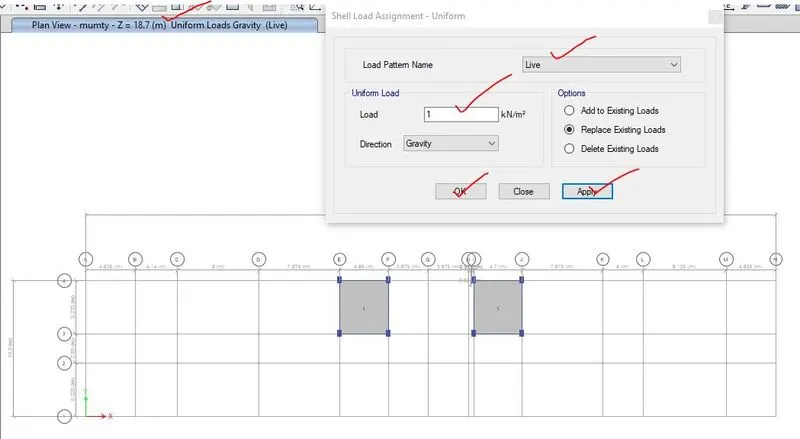
- Terrace and mumty-1 kN/m
1.2.3 Calculation brick wall load and floor finishing
Density of ACC block= 6kN/m
Density of cement mortar= 20kN/m
Thickness of wall= 0.15mm
Height of the wall= 3.45-0.45= 3m
Weight of wall= (3×0.15×6) = 2.7 kN/m
Assuming thickness of plastering=0.024m
Load for plastering= (3×0.024×20) = 1.44 kN/m
Total brick wall load= 2.7+1.44= 4.14 kN/m which is nearly equal to 4.2 kN/m.
Floor finishing= 1.2 kN/m3
1.2.4 Time factor calculation
- As per IS 1893:2016, clause-7.6.2 (c), page no-21
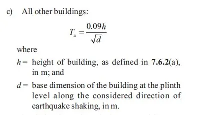
Height of the building=18.7m
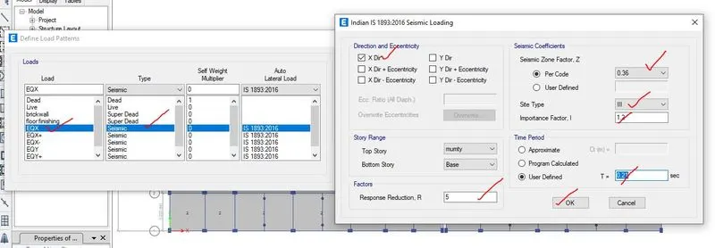
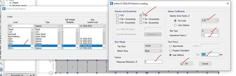
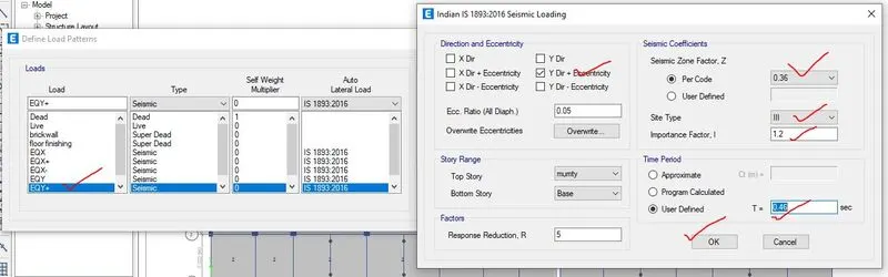
Time factor in y direction where d=13.3m, Tx=((0.09×18.7)/square root(13.3))= 0.4615=0.46
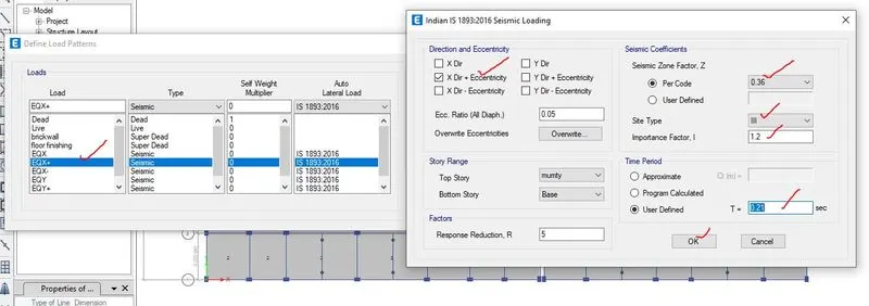
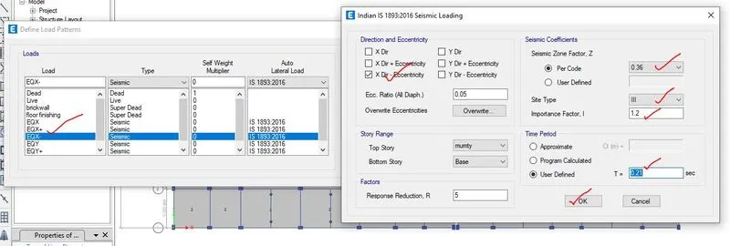
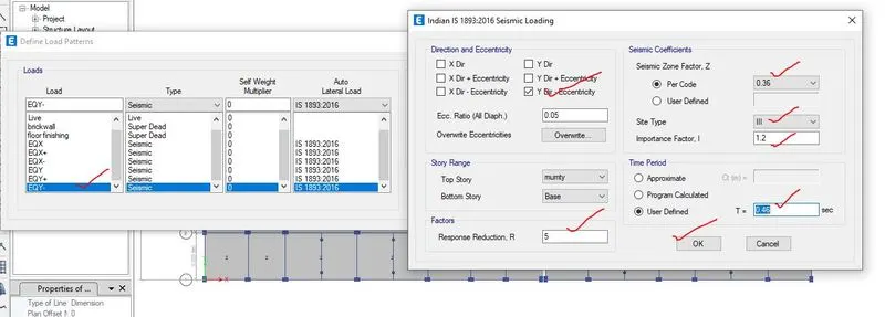
Time factor in x direction where d=66.62m, Tx=((0.09×18.7)/square root(66.62))= 0.2062=0.21
1.3 Analysis and design for beam and column of the hostel building by using ETABS
1.3.1 Procedure in modelling, analysis of the hostel building
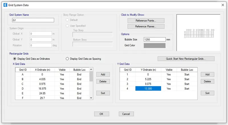
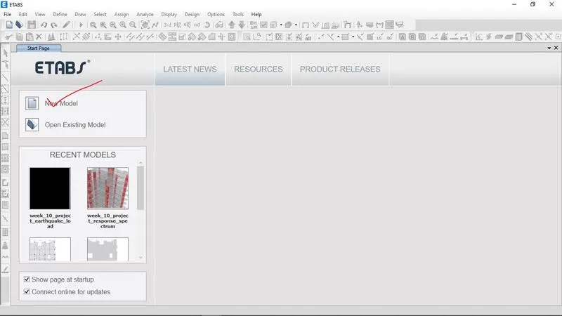
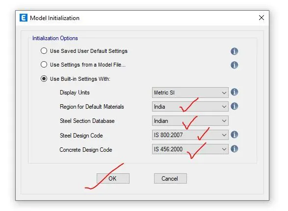
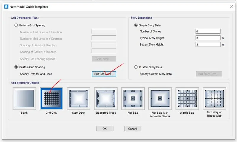
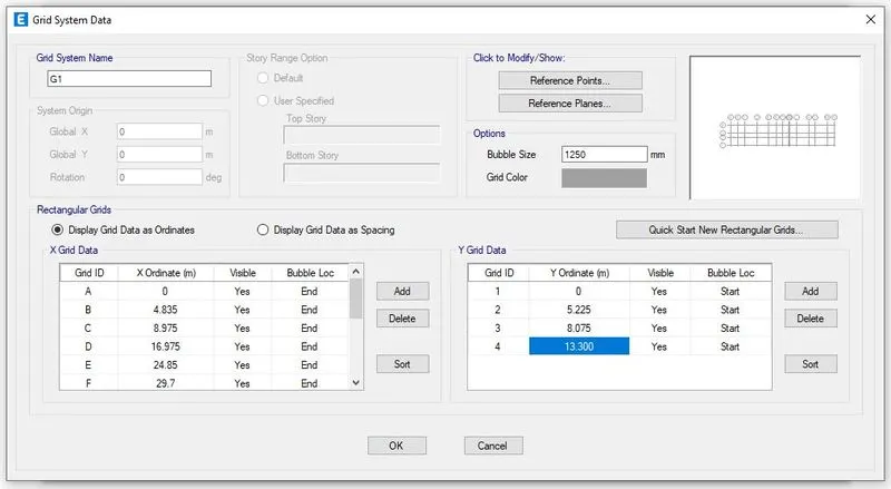
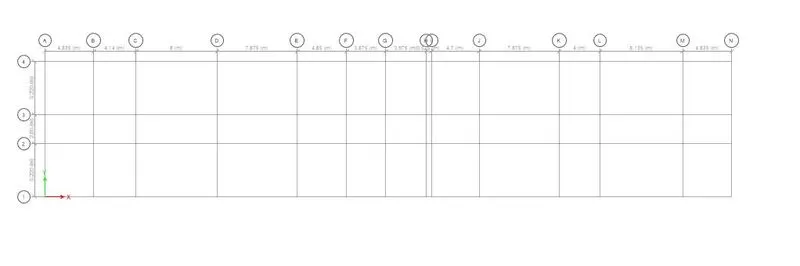
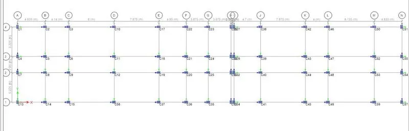
Step-1- firstly ETABS has been opened and then a new model has been created with appropriate codes and unit system and then grid has been created according to the beam-column layout with x and y grid data which has been given below,
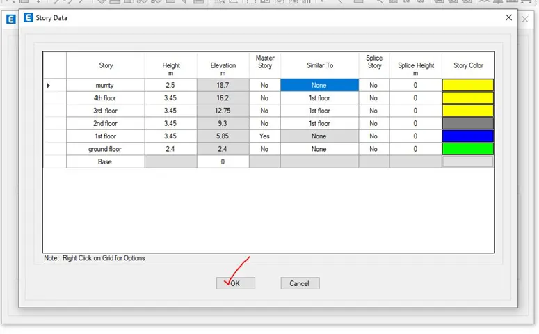
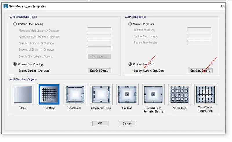
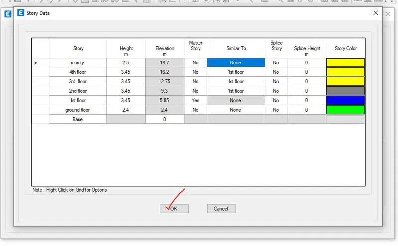
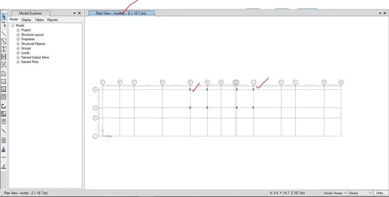
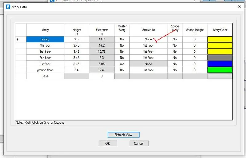
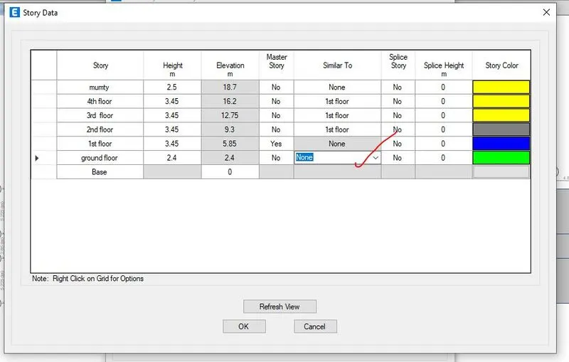
Step-2- Then story data has been added according to the elevation diagram that has been show above.
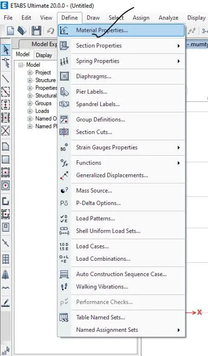
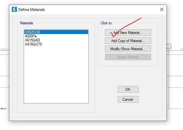
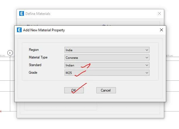
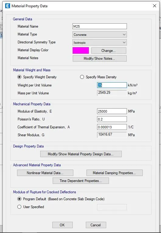
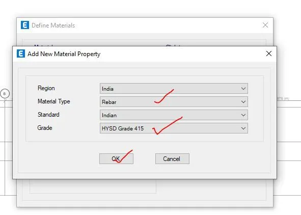
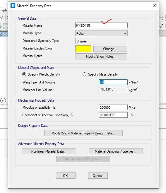
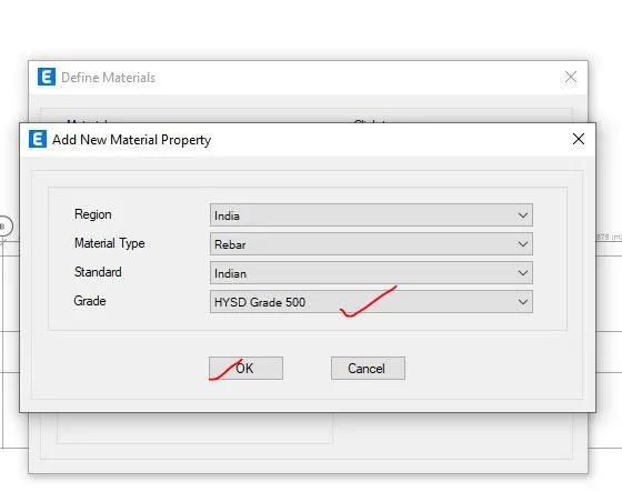
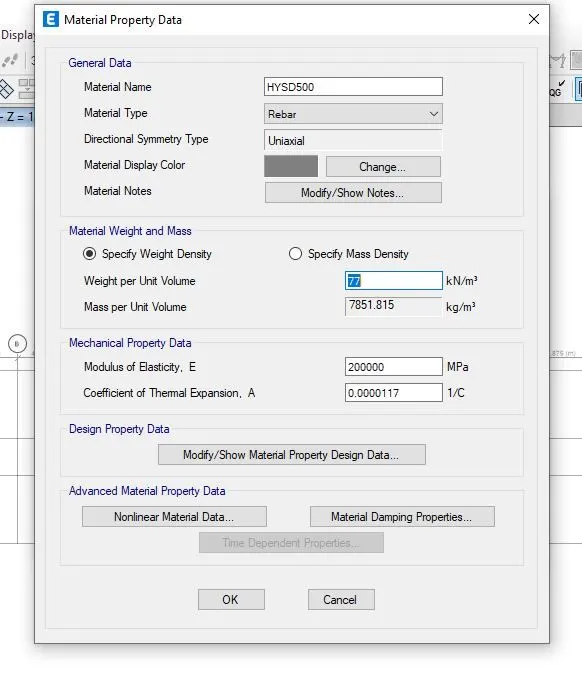
Step-3- After creation of x and y grids and story data, material like grade of concrete M25,M30, Fe415, Fe500 for rebar has been define as per the requirement and material propertied has been added.
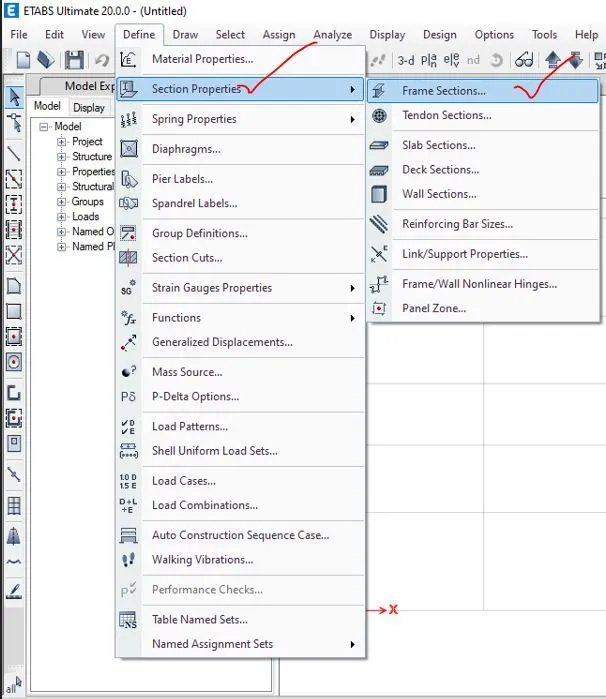
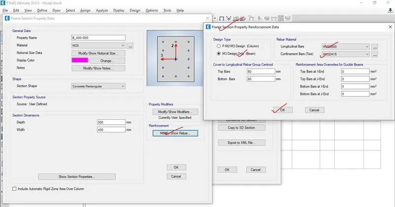
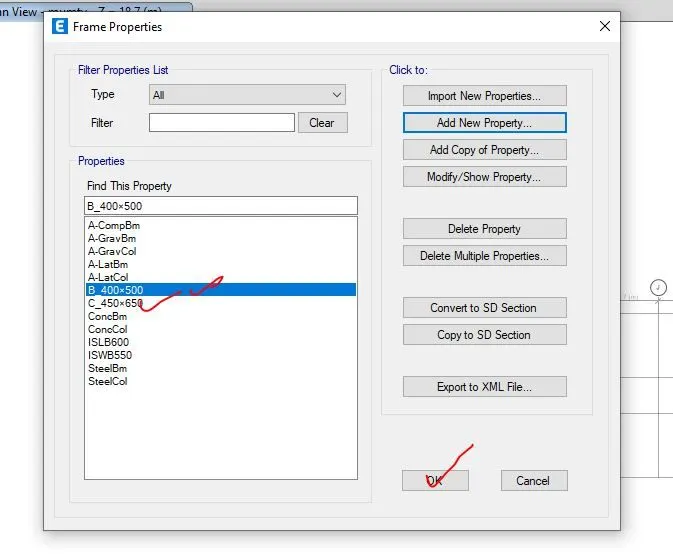
Step-4- Step 5-After defining the material properties, frame properties of the model has been defined by clicking on the define option and then section properties and then frame properties then a pop-up will be opened.
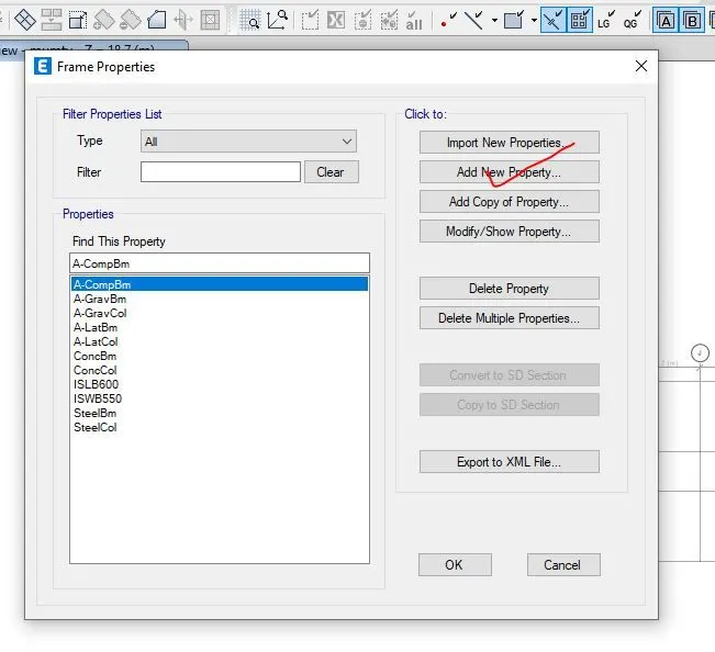
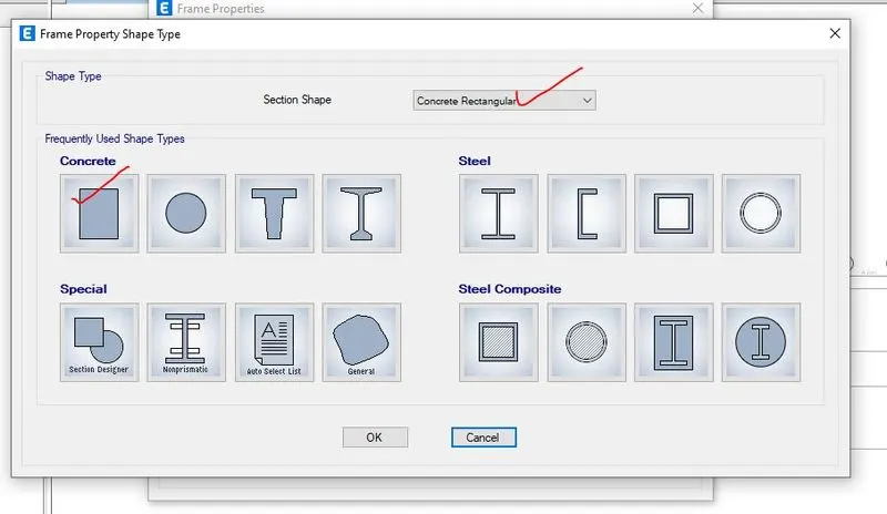
After a pop up box is opened, then by clicking on the add new properties and then specify the concrete rectangular and then rectangular section and then another pop up box frame section propertied data will be opened where properties name, material, section dimension, property modifier and reinforcement details has been assigned.
For this project, the data for column as well as beam also has been added that is given below,
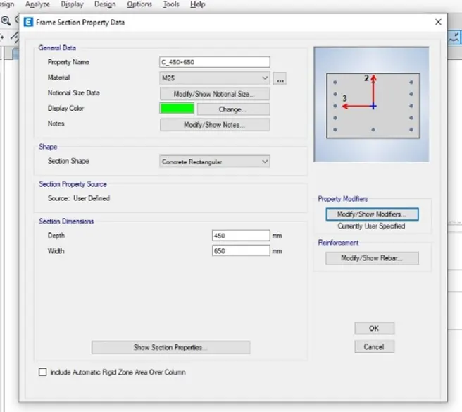
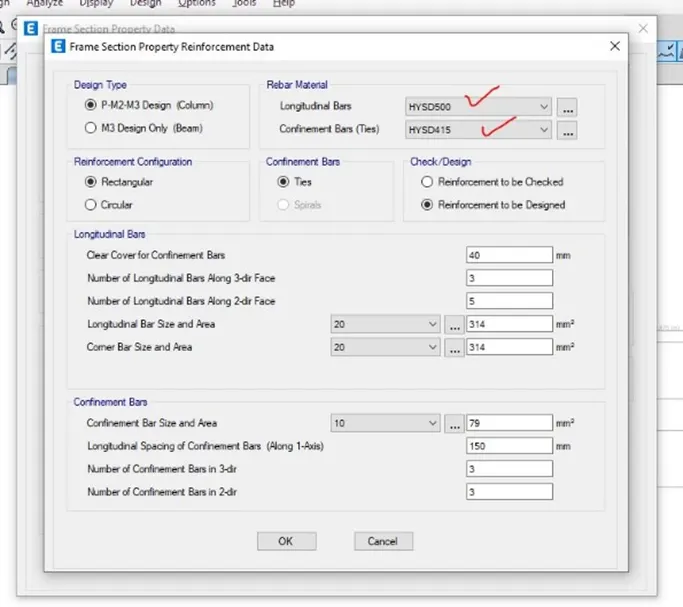
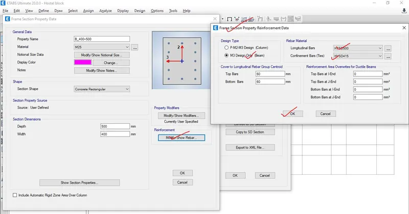
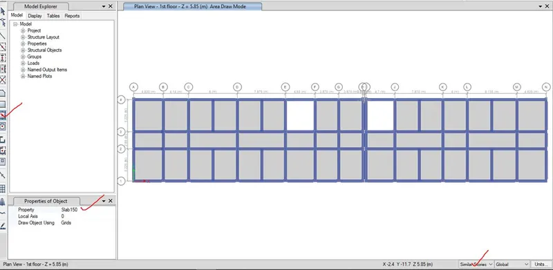
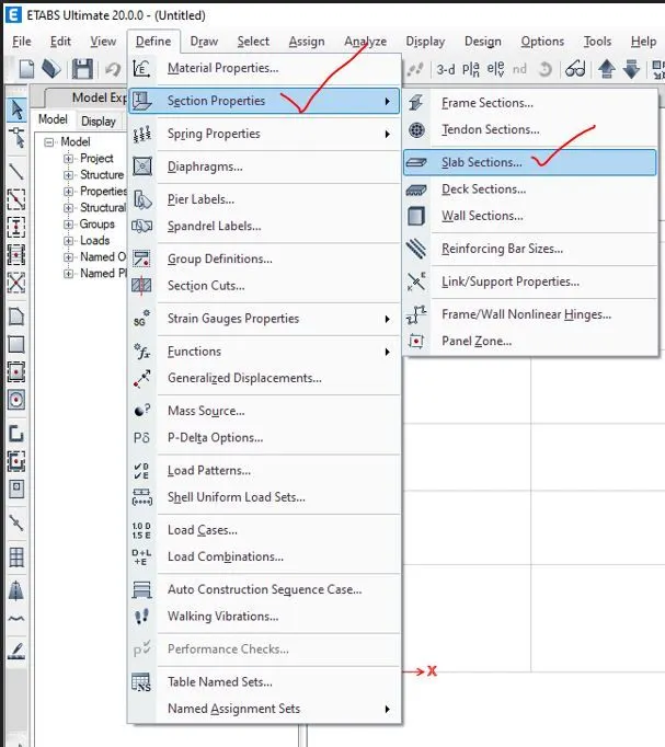
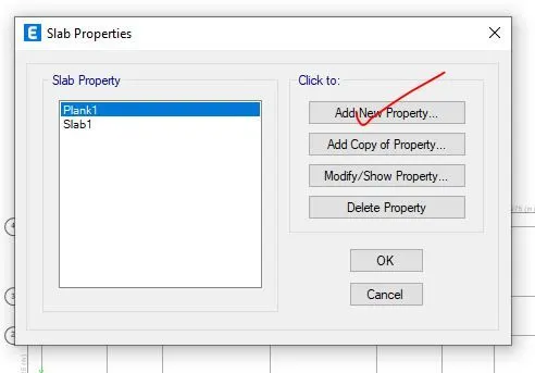
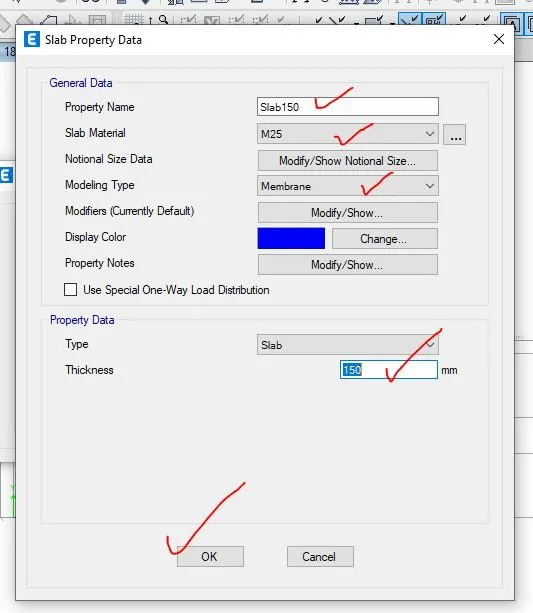
Step-5- For defining of the section properties of slab, go to the define and then clicking on section properties and then click on the slab definition, and then as per the given data which has been shown below,
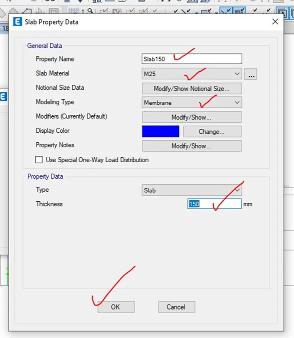
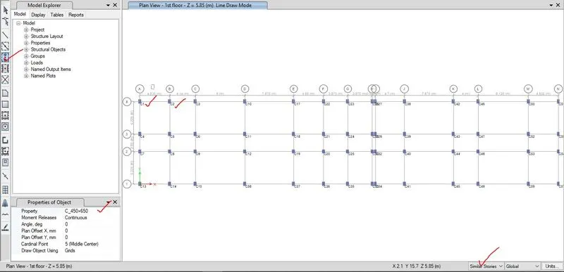
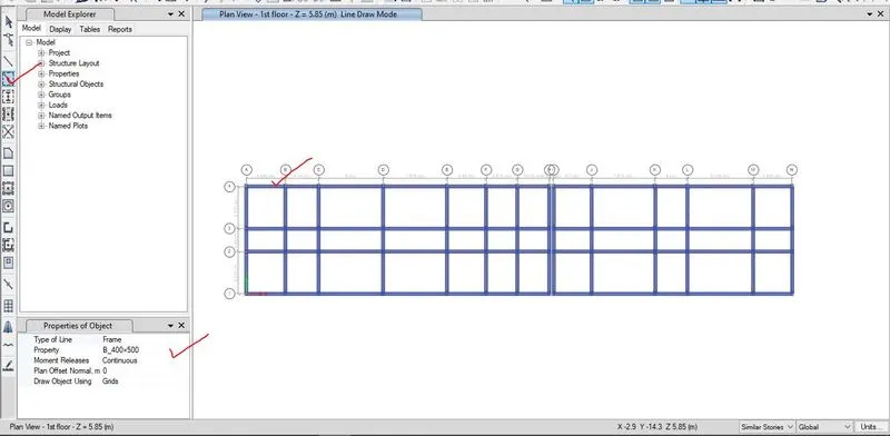
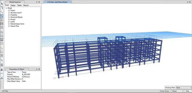
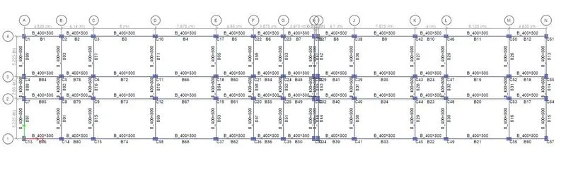
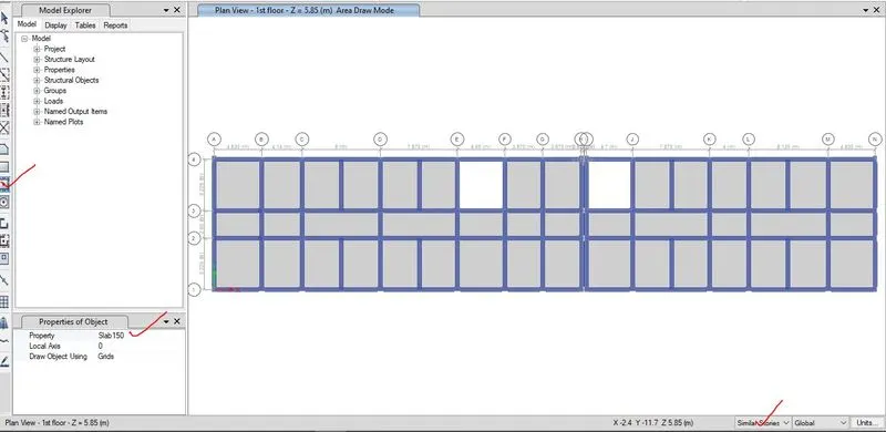
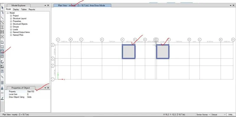
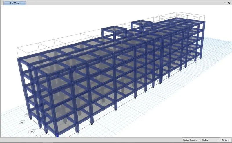
Step-6- After defining the material properties and frame properties, by using the quick draw beam and column, the beam and column have been created and in the same procedure by using quick drawn floor the slab also has been created with respect to the beam-column layout.
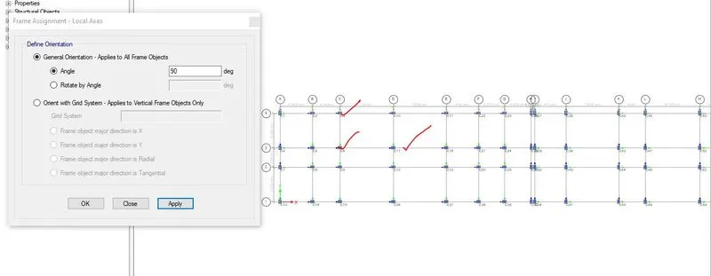
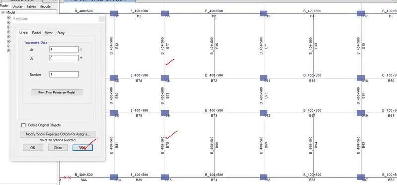
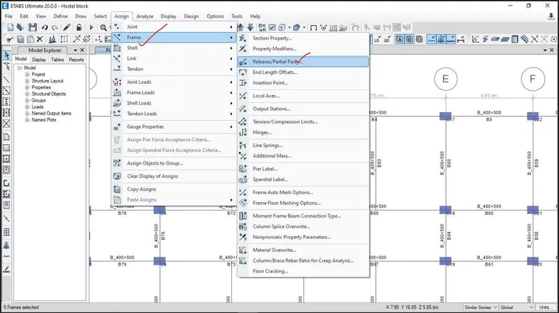
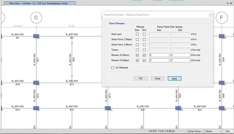
Secondary beam has also has been created at appropriate place as simply supported beam. After drafting of secondary beams, as per structure requirement, the internal hinged i.e. moment release has been added by using frame assignment.
Assign-à frame assignment à Releases/ partial fixity.
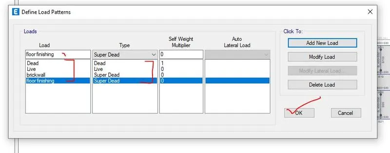
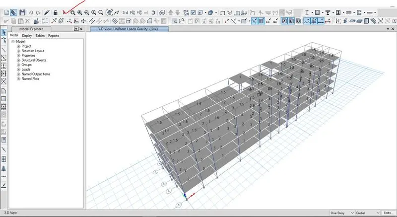
Step-7- Now the load pattern has been defined I.e. wall load that has been calculated above, live load has been decided according to the IS 875 part II , dead load and seismic load i.e. EQX (in x direction) and EQY (in y direction) with supporting of IS code of 1893:2016.
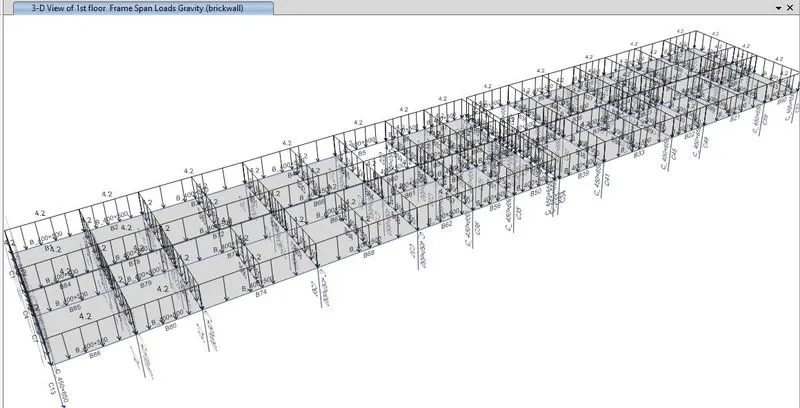
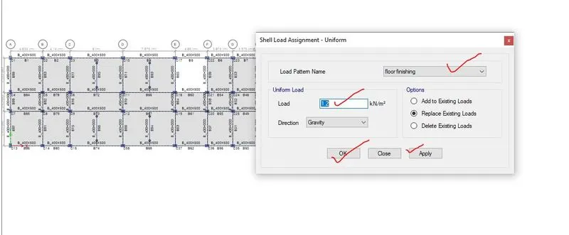
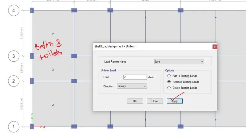
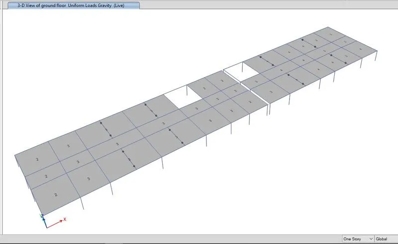
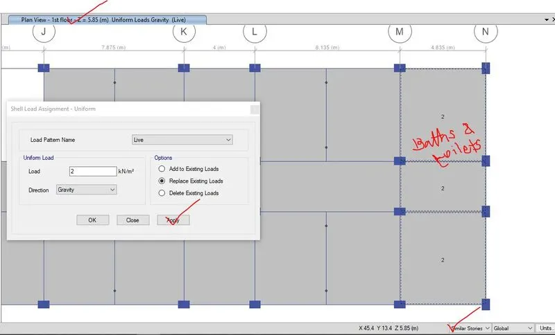
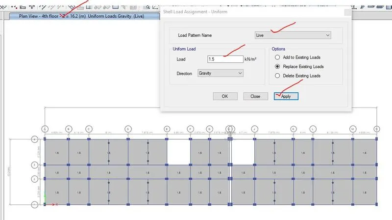
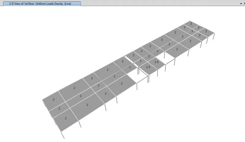
After defining of load pattern, then the different load has been assigned where wall load has been assigned to all the beams and live load to the floor as per IS code that has been discussed above.
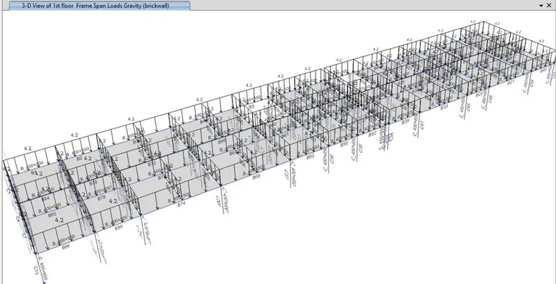
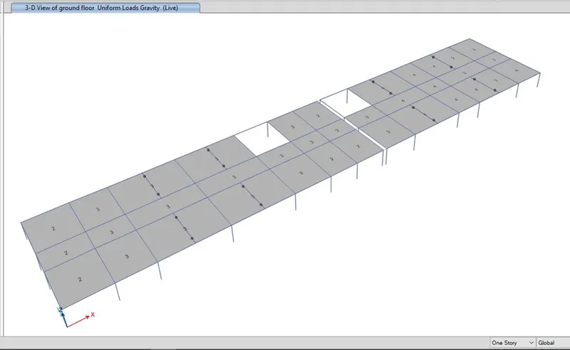
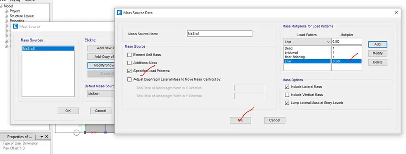
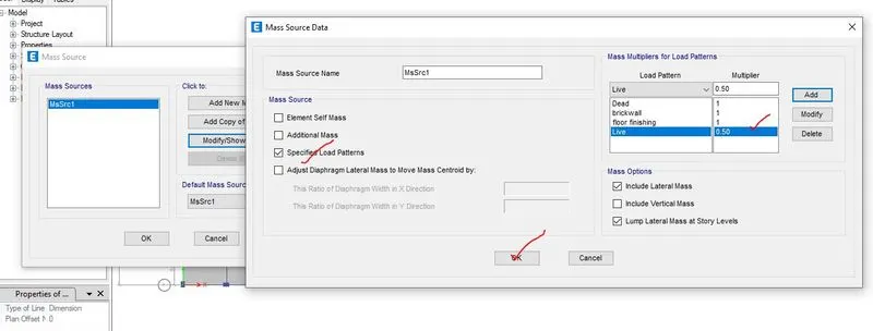
Step-8- After assigning of the different loads, mass sources data has been added by clicking on the define option and then mass source where % mass has been defined for dead load, live load or imposed load and for wall i.e. super dead load which is given below,
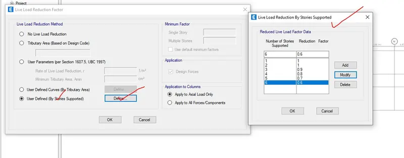
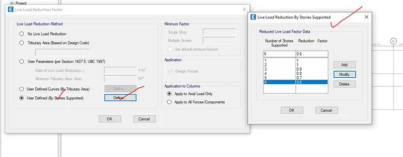
Step-9- Live load reduction factor for each floor as per IS code has added.
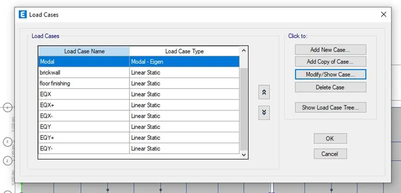
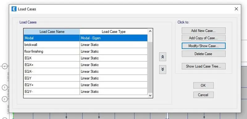
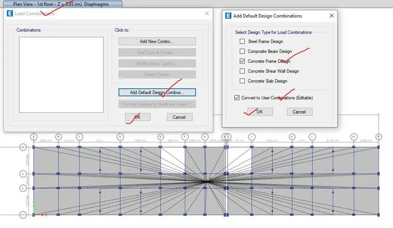
Step-10- check for the load cases which will be found on the define option and then the load combination is added from define option and by clicking on add default design combo for concrete frame structure which is given below,
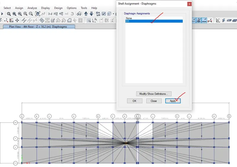
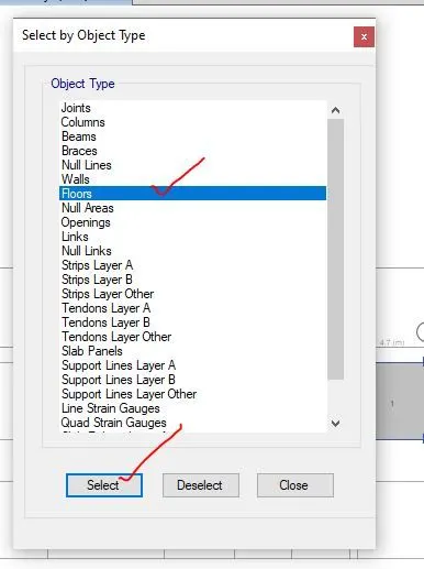
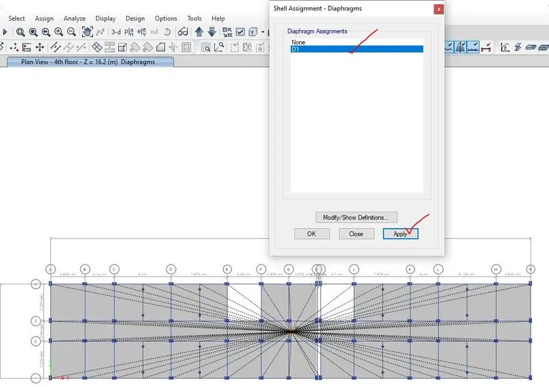
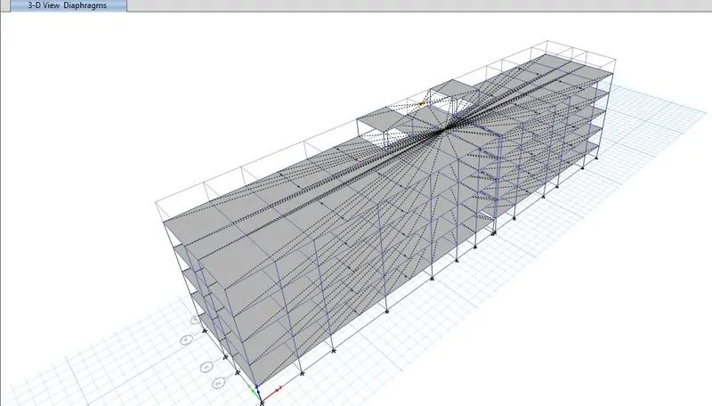
Step-11- Here in this step, diaphragm is added to all the floor after selected all the floor.
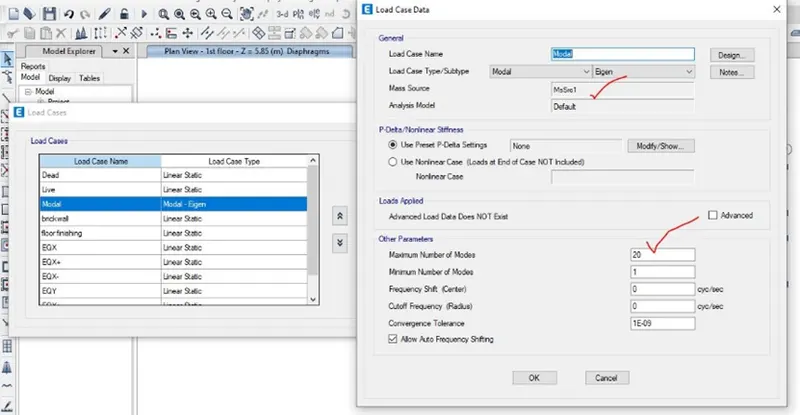
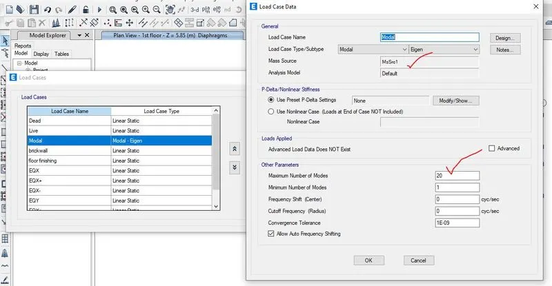
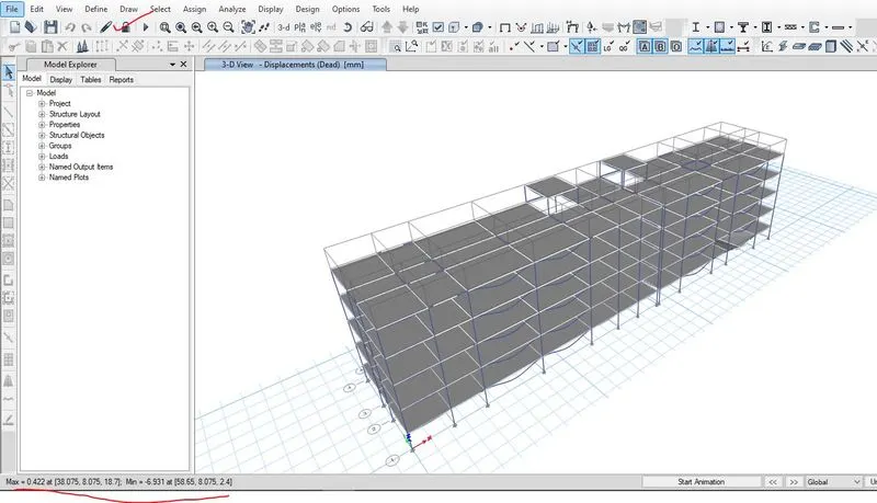
Step-12- After assigning the material property to columns, beams and slab, different type of load to model, in the next step load combination has added as default design combination and then for modal analysis, modal property has been added where the mass source has been added. Then, for this load combination of dead load, live load, earthquake load and modal, this model has been analyzed by clicking on the run bottom.
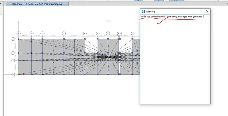
Before analysis, the model has been checked for error and warning and the error has been resolved before analysis.
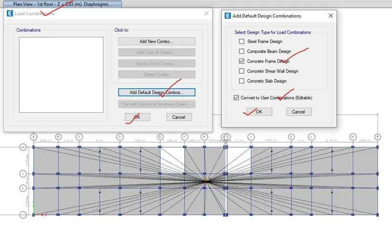
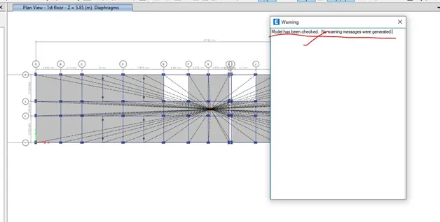
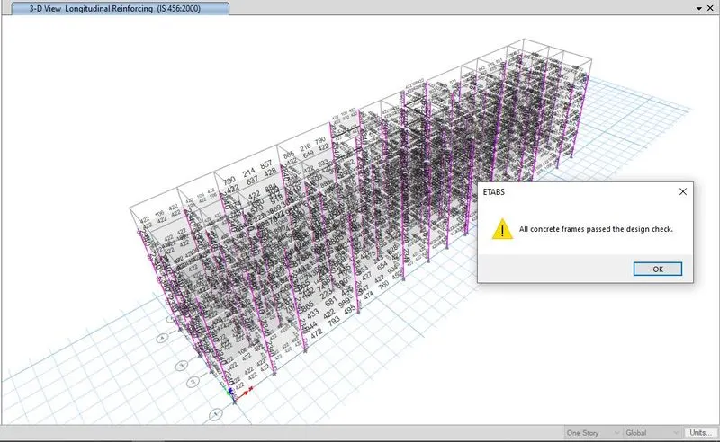
Step-13- After completion of analysis, the analysed model has been design by clicking on the concrete frame design bottom which designs the longitudinal reinforcement and shear reinforcement for all the load combination of all the members in the model which can be checked by clicking on drop down bottom of concrete frame design and the by clicking on display design info.
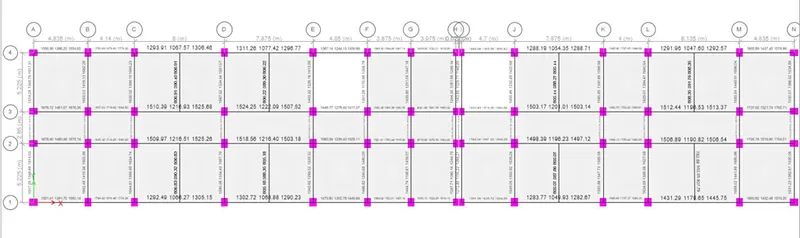
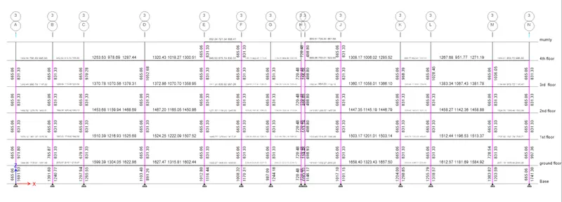
The amount longitudinal reinforcement and shear reinforcement has been given below,
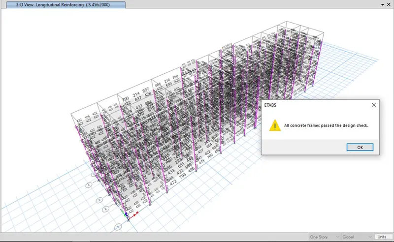
1.3.2 Amount of longitudinal reinforcement
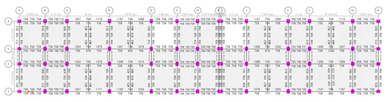
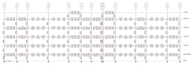 1.3.
1.3.
1.3.3 Amount of shear reinforcement
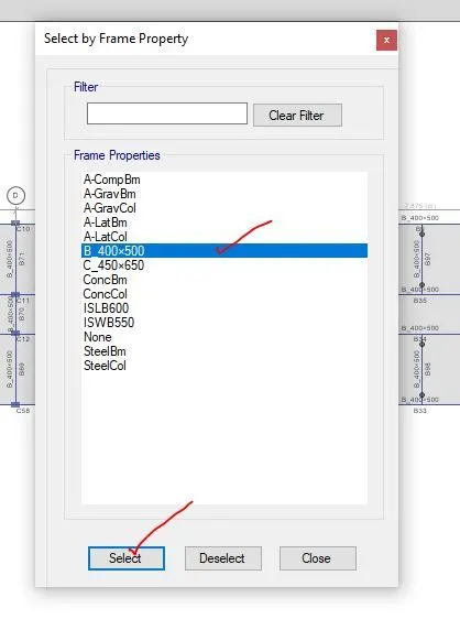
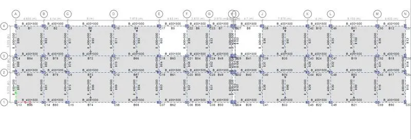
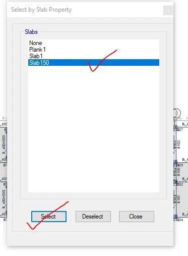
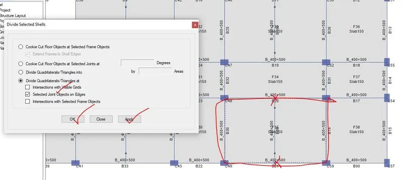
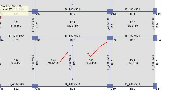
1.3.4 All the step wise screen shots in analyzing and designing the concrete frame structure is given below,
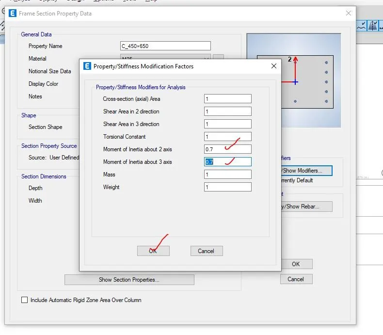
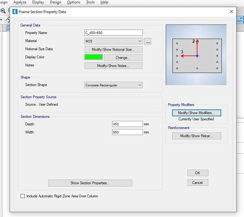
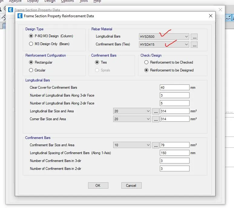
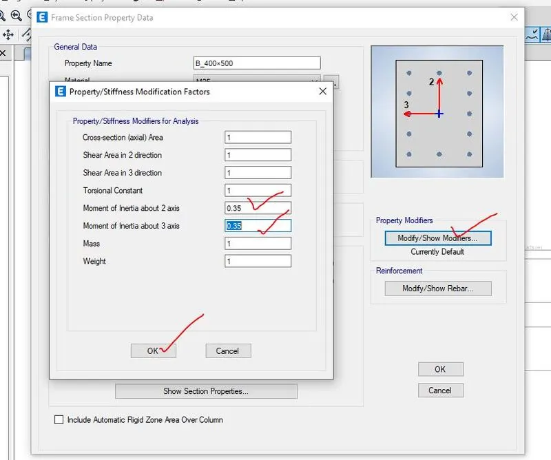

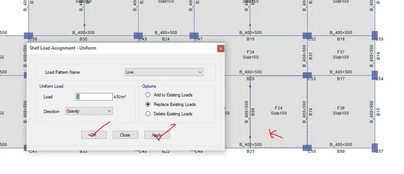
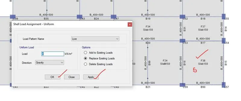
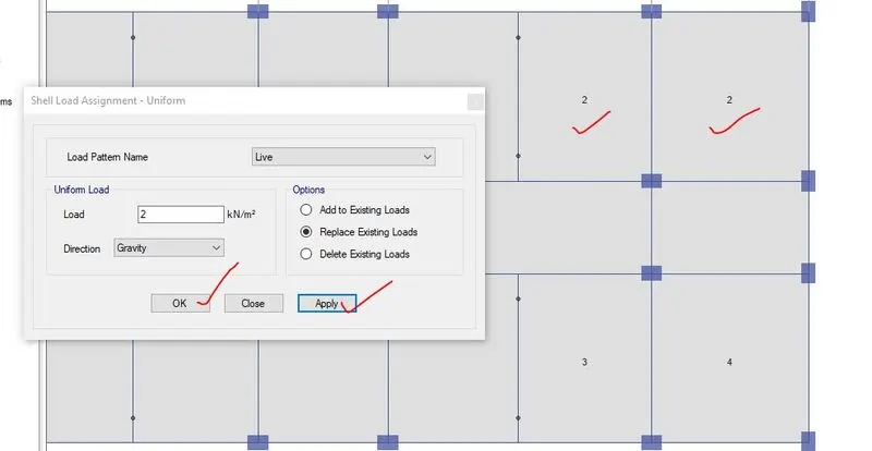
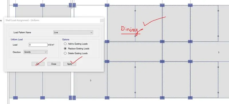
1.3.5 Detailing of beam in the hostel block by ETABS
Design details i.e. flexural details and shear details for all the load combination of every members in the model can be checked by right clicking on the required members and directly the designs can be access.
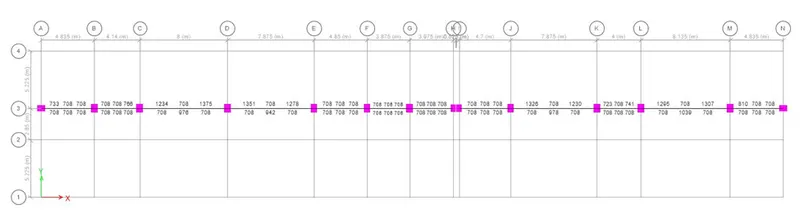
After finding the design details, then for grids 3 at 3rd floor the detailing has been done.
1.3.6 Results and Discussion
- Detailing rule of reinforcement concrete members
- Minimum reinforcement for shrinkage and temperature
- Reinforcement required for limiting cracking width
- Ultimate limit state design rebar reinforcement
- Ductility rebar reinforcement
RC beam detailing is chose whichever is greater among above condition 1, 2, 3 and 4.
- Minimum longitudinal reinforcement as per IS 13920-2016 clause 6.2.1.
AS= 360 mm2
- Minimum shear reinforcement as per IS 456-2000 clause 26.5.1.6 assuming 1 meters spacing in the formula,
ASV= 554 mm2
- Development length as per IS 456-2000 clause 26.2.1
Ld= 50 × diameter of bar
For 20mm dia, Ld= 50 × 20mm= 1000mm
For 25 mm dia, Ld= 50 × 25mm= 1250mm
- Longitudinal reinforcement for Grid 3
- Shear reinforcement for Grid 3

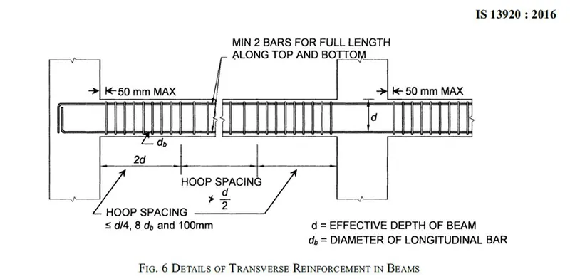
- Additional reinforcement for guideline from IS 13920-2016
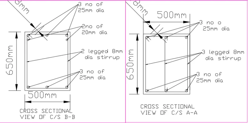
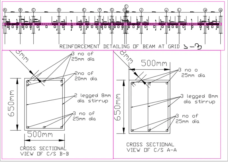
- After getting the value of longitudinal reinforcement and shear reinforcement for grid A and grid 3, the detail reinforcement has been drafted using AUTOCAD which is given below,

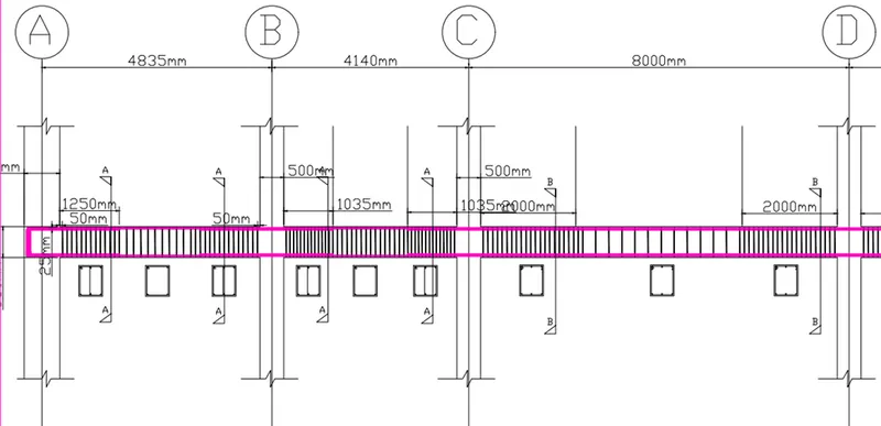
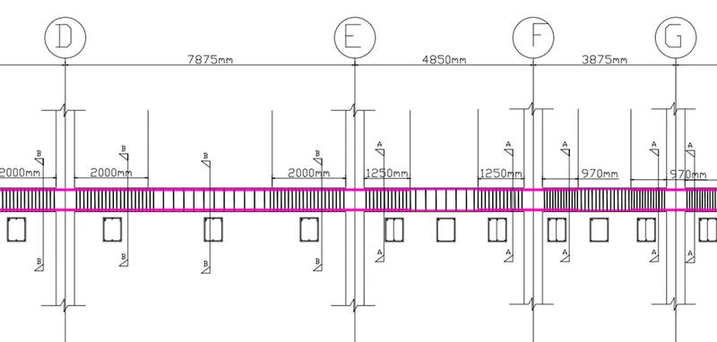
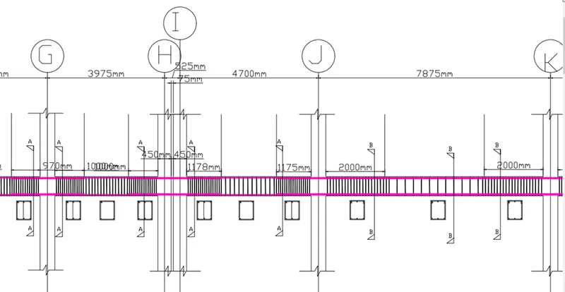
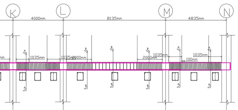
- Beam cross sectional view,
1.3.7 Detailing of column in the hostel block by ETABS
Results and Discussion
- Detailing rule of reinforcement concrete members
- Minimum reinforcement for shrinkage and temperature
- Ultimate limit state design rebar reinforcement
- Ductility rebar reinforcement
RC beam detailing is chose whichever is greater among above condition 1, 2 and 3.
- Minimum longitudinal reinforcement as per IS 456-2000 clause 26.5.3.1.
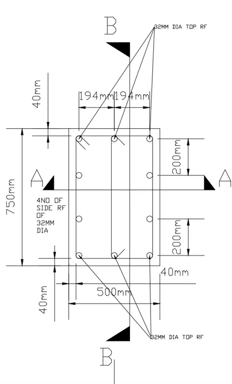
AS= 3000 mm2
- Minimum shear reinforcement or transvers reinforcement as per IS 13920-2016 clause 7.4.2
8mm diameter at 300mm spacing
- Development length as per IS 456-2000 clause 26.2.1
Ld= 50 × diameter of bar
- Special confining reinforcement from IS 13290-2016 (clause 8.1)
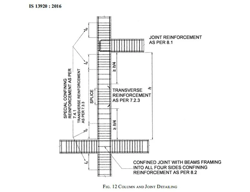
1.3.8 Calculation of l0, which would be the maximum value among following three value i.e. 1, 2, and 3.
- Larger column dimension= 750mm
- (1/6)th of clear span of column
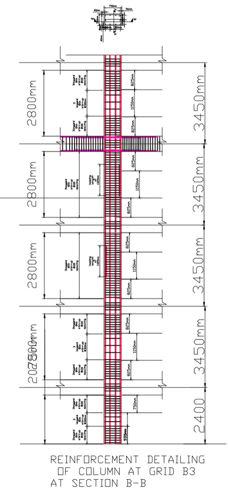
= (1/6) × 2800 = 812.5 mm for column of span 3450 mm.
= (1/6) × 2075= 345.83 mm for column of span 2400 mm.
- 450mm
So, l0 = 812.5 mm as it is higher value among 1, 2 and 3. So provide 825mm of l0
1.3.9 Calculation of confinement of spacing, which would be the minimum value among following three value i.e. 1, 2, and 3.
- (1/4)th of smaller column dimension = (1/4)× 500= 125 mm
- 6th time of diameter of column main bar= 6× 32= 182mm
- 100mm
Hence the confinement of spacing is 100mm.
1.3.10 Calculation of amount of confinement rebar,
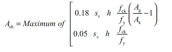
Ash= 81.51257mm2
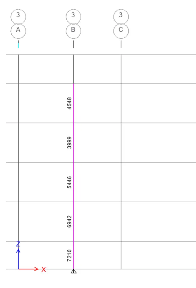
- Longitudinal reinforcement of column for Grid 3B
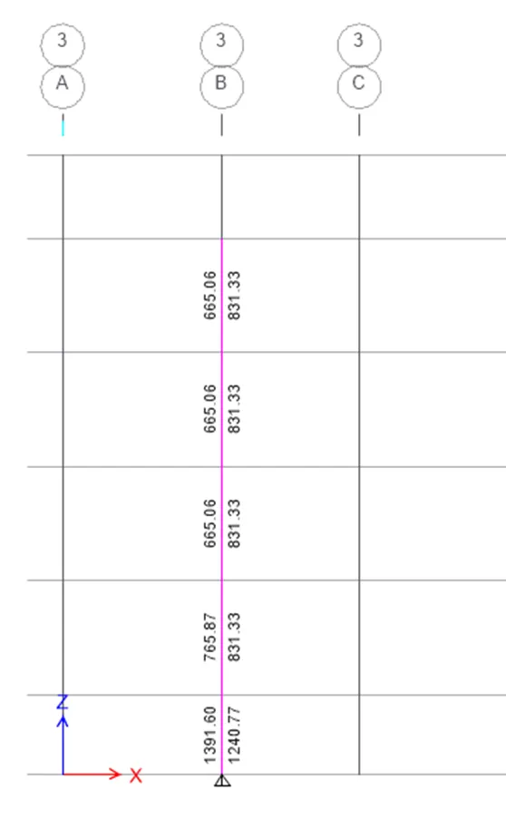
- Shear reinforcement of column for Grid 3B
- After getting the value of longitudinal reinforcement and shear reinforcement columns at grid intersection 3B from ETABS, the detail reinforcement has been drafted using AUTOCAD which is given below,
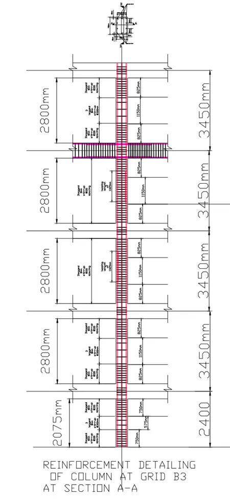
- Column cross section
1.3.11 Analysis and design for foundation of the hostel building by using SAFE with ETABS outputs
1.3.12 Data required for SAFE analysis and design,
- Square footing of column size 450×650 mm
- Compressive axial load combination which has been exported from ETABS which is supported on the pile cap that is given below.
- The buildings rests on type 3 soil. Piles of length 10 meters and 500 mm diameter with load carrying capacity of 280 KN.
- Safe soil bearing capacity is 150kN/m2.
- Area of the pile cap = (total load× 1.1)/ soil bearing capacity
For grid intersection A2,
Area of pile cap= (881 ×1.1)/150= 6.46 m2
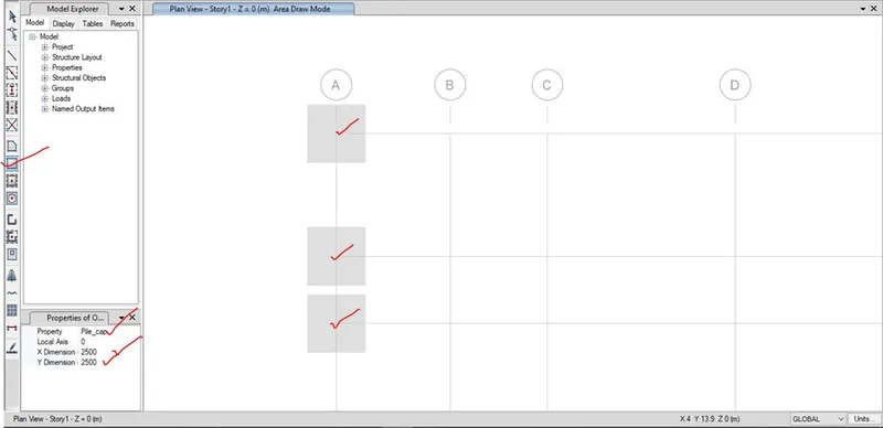
As the pile cap is assumed as square shape, so the width of the pile cap = sqrt (6.46 m2)= 2.5m
For all the pile cap, the area and width has been calculated which has been given in the excel file.
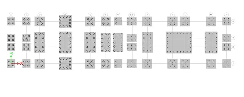
Minimum Number of pile required= (total load/ pile load capacity)
For grid A2, Minimum Number of pile required= (881/ 280)= 3, so provide 4 no of pile.
For all the grid intersection, minimum numbers of pile is calculated which has been uploaded as excel file.
1.3.13 Subgrade modulus for soil calculation,
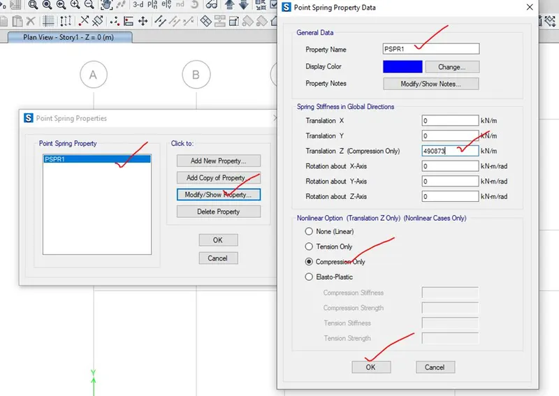
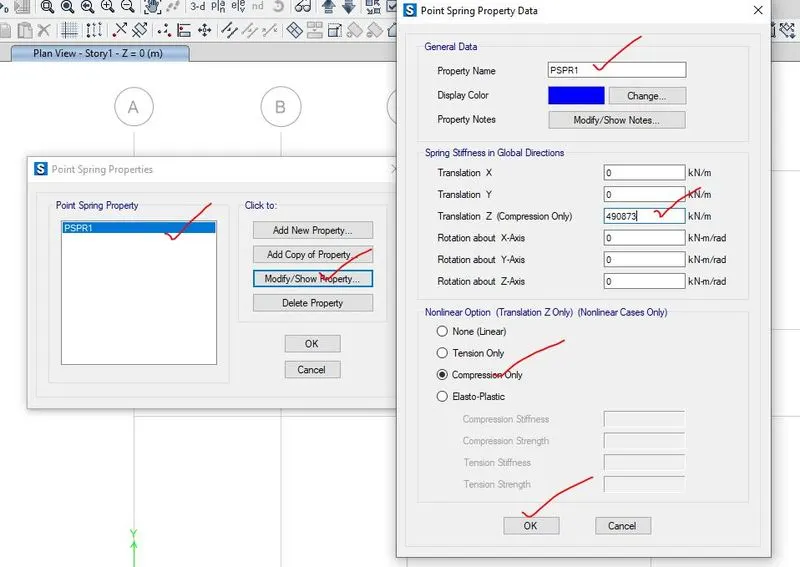
Point spring of pile = A ×E /L =196349×25000/10000=490873 kN/m
Point spring of pile =490.9 kN/mm
Elastic modulus of M25 concrete= 25000 N/mm2
Subgrade modulus for soil calculation,
Point spring of pile = A ×E /L =196349×25000/16000= 306795.3125 kN/m
Point spring of pile =306.8 kN/mm
1.3.14 Procedure in modelling, analysis of footing for the hostel building
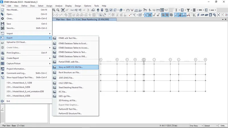
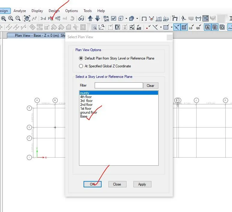
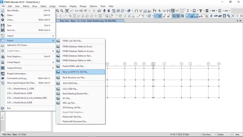
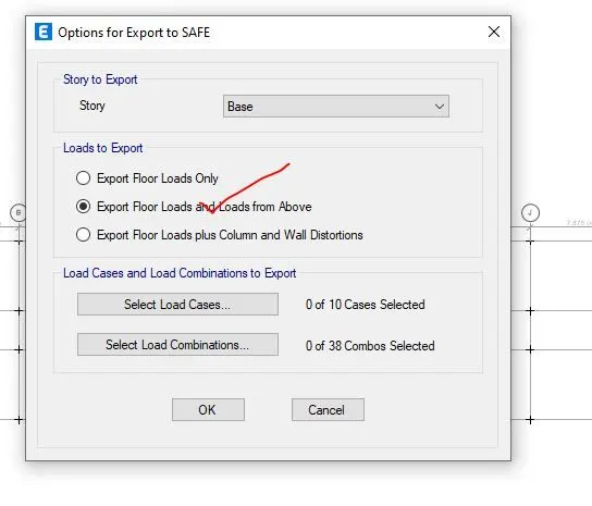
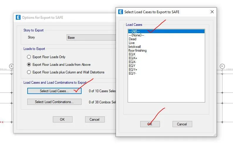
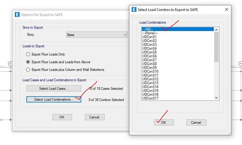
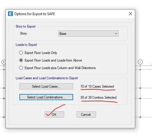
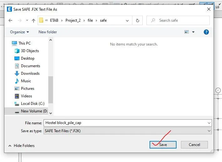
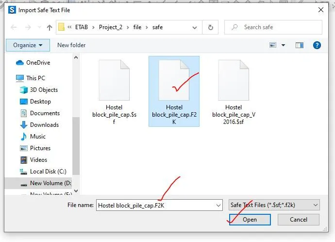
Step-1- Firstly, the model has been opened in the ETABS and then this model has been exported as F2K file and saved in the appropriate location where the ETABS file exported as story as SAVE v12 .f2k file for the base only and the loads is exported as export floor load and loads from above where all the loads and loads combination has been selected.
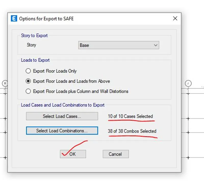
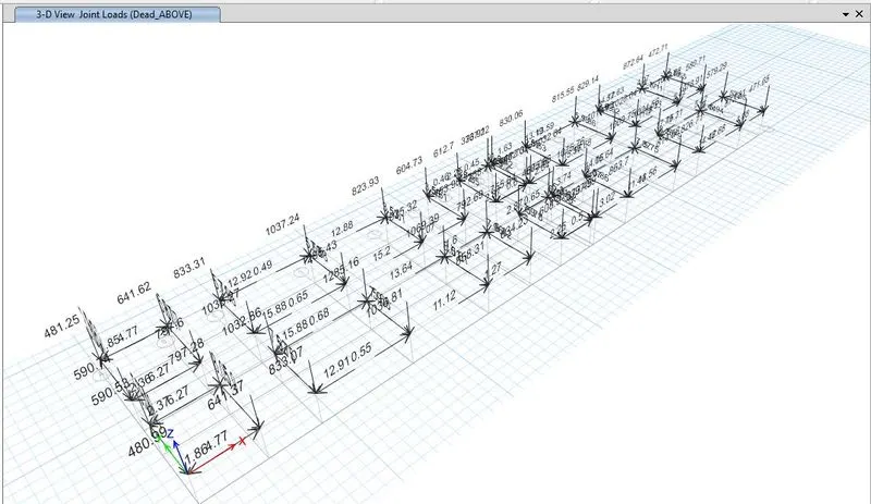
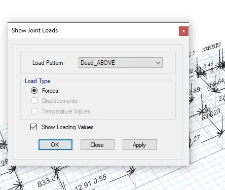
Step-2- The exported .f2k file has been opened in the SAFE software and loads above has been checked.
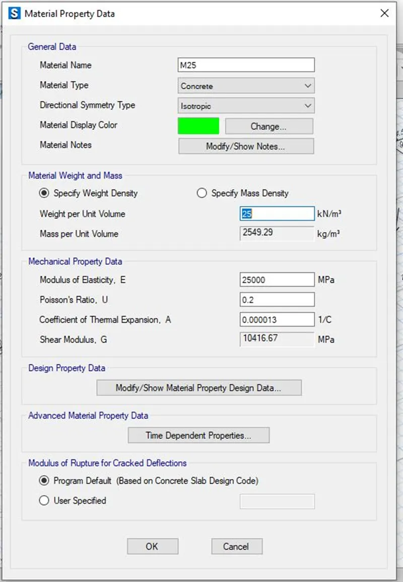
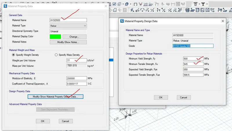
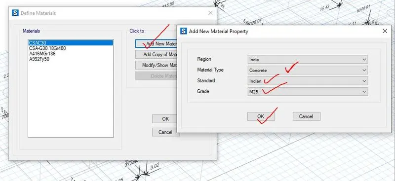
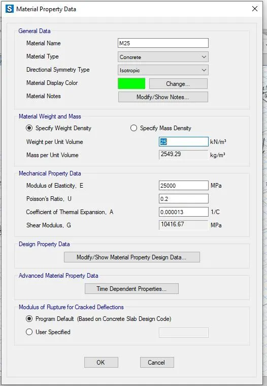
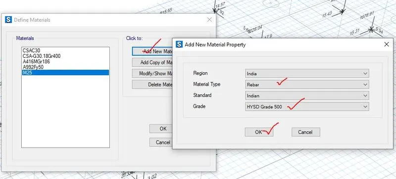
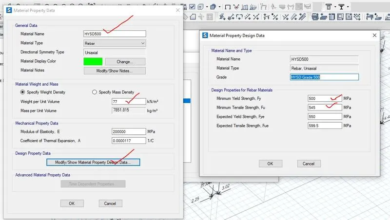
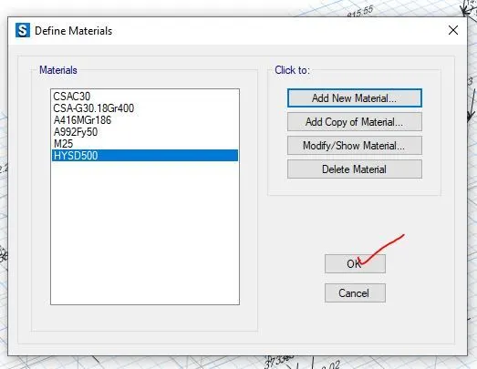
Step-3- The material properties for concrete i.e. M25 and M30 and for rebar i.e. fe500 grade has been define which has been shown below,
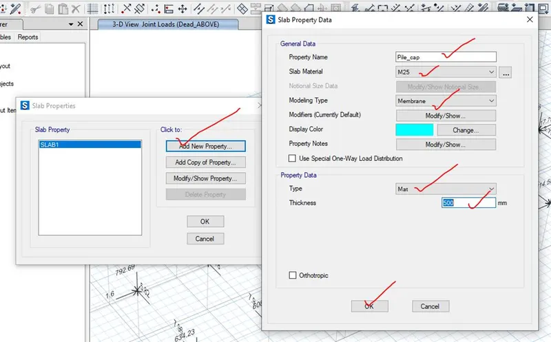
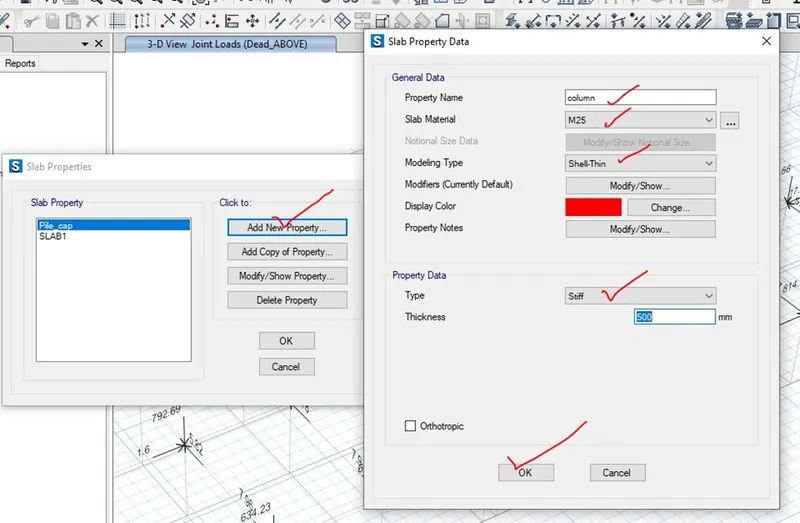
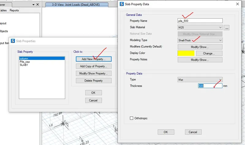
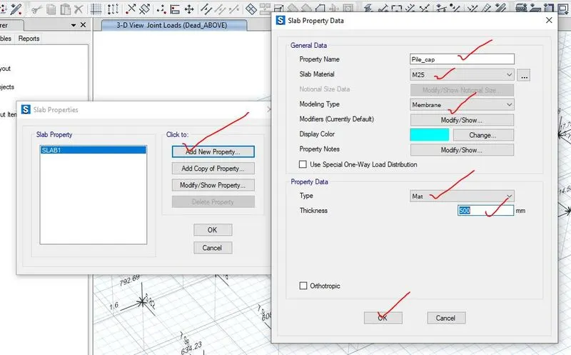
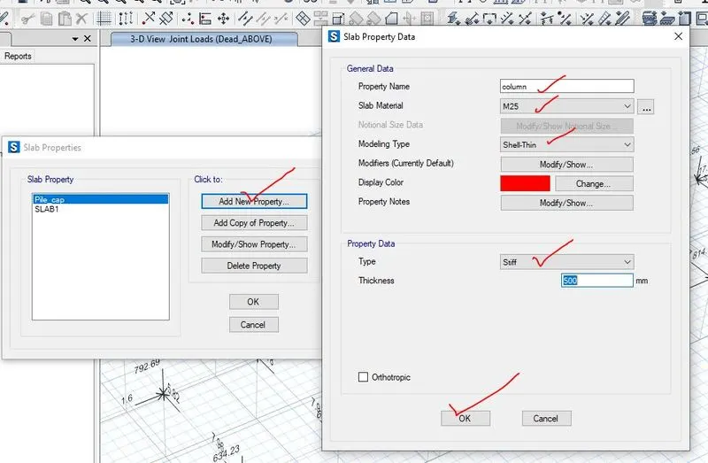
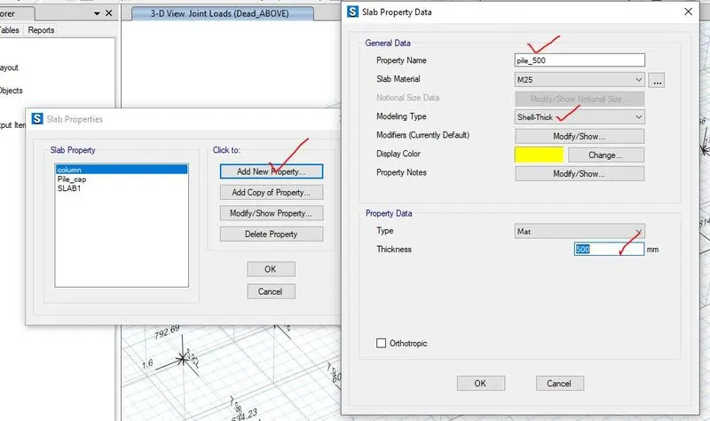
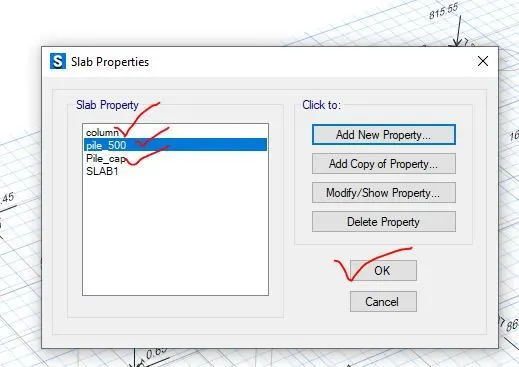
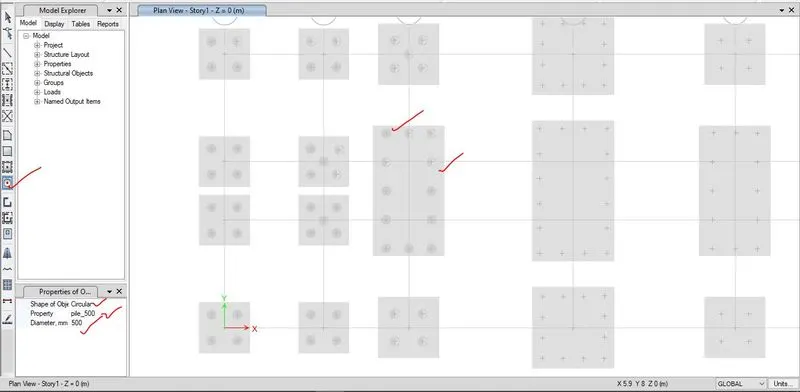
Step-4- After addition of material properties of concrete and rebar, the slab properties has been added where two slab has been added as pile cap as mat type, column as stiff type and pile_500 as mat type.
Step-5- In this step point spring property data has been added which has been calculated above.
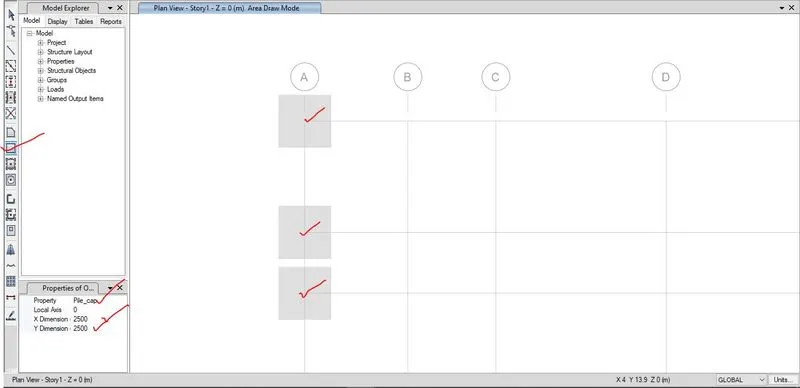
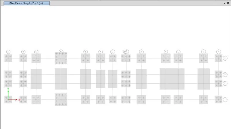
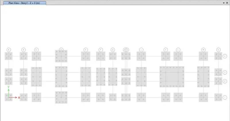
Step-6- By using the draw rectangular floor/ wall tool, the rectangular pile cap has been drafted according their respective width which has been calculated as above.
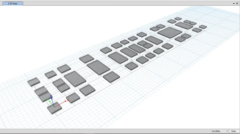
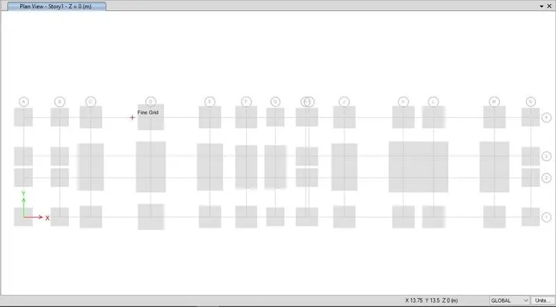
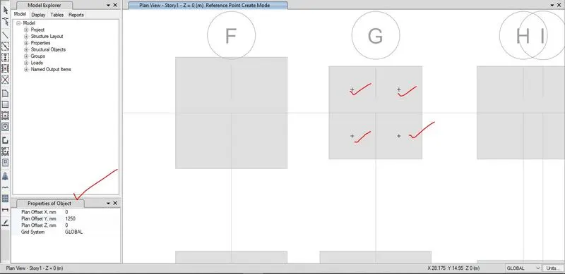
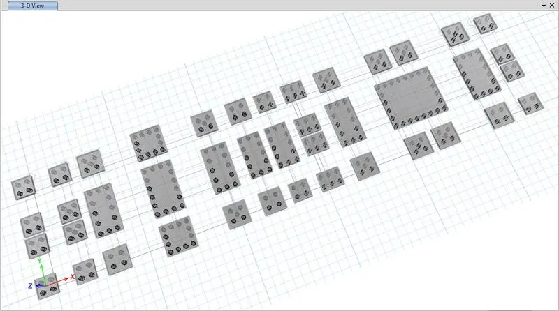
Step-7- by using draw point object tool, the points for locating the pile cap has been draw with respect to their location.
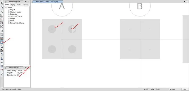
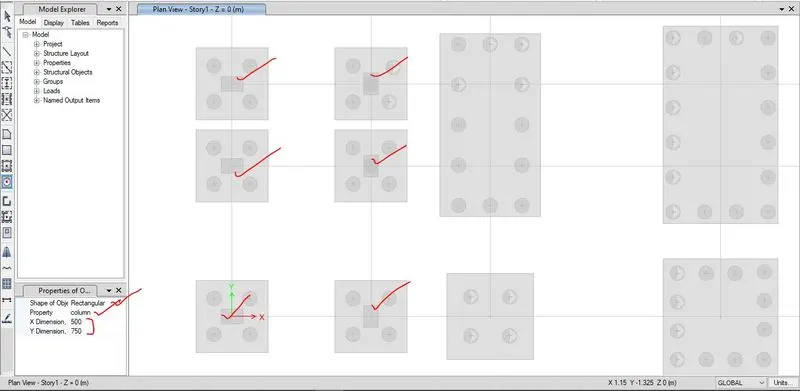
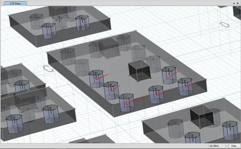
Step-8- After drafting of the points, the columns and pile has been assigned to the appropriate location.
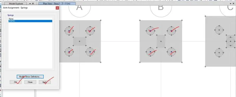
Step-9- Here, point spring properties has been assigned to all the pile.
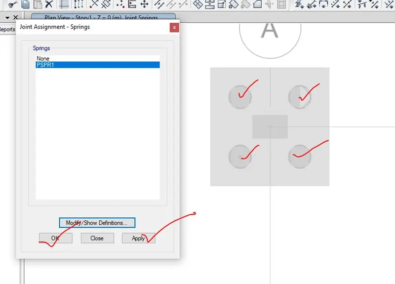
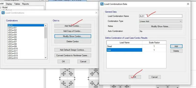
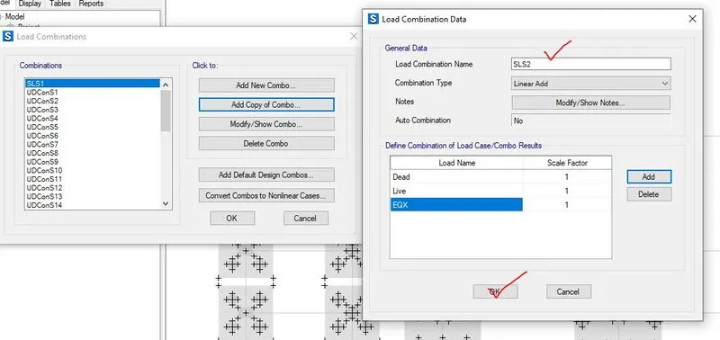
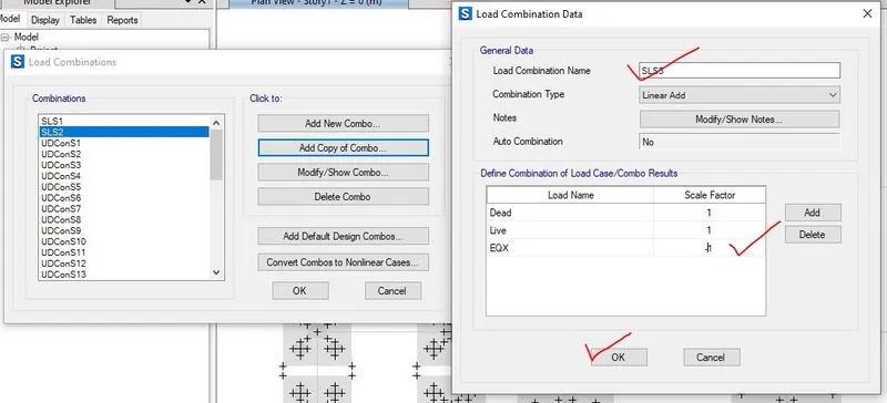
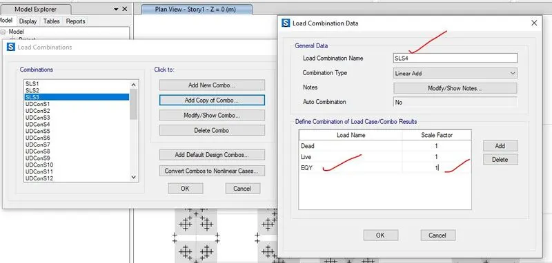
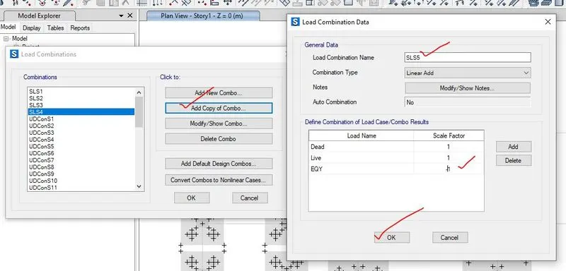
Step-10- Now, the load combination for service load has been added as SLS1, SLS2, SLS3, SLS4 and SLS5.
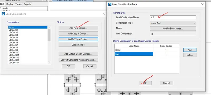
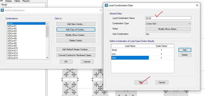
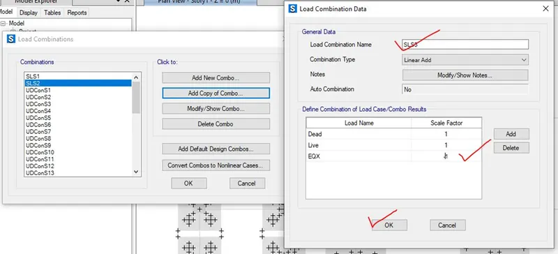
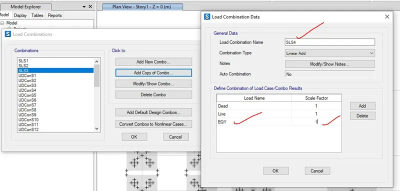
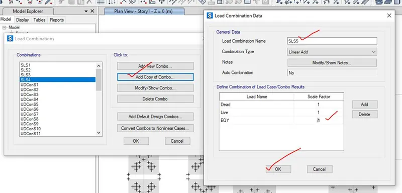
Step-11- this model has been analyzed by using the run bottom checked for shear failure and soil bearing capacity.
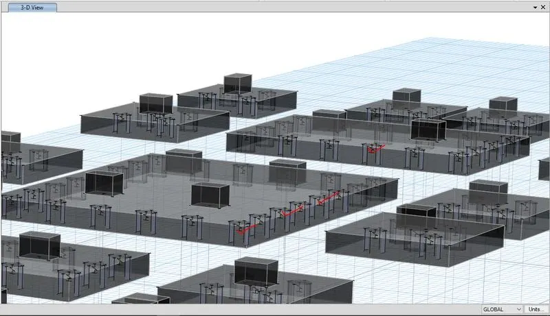
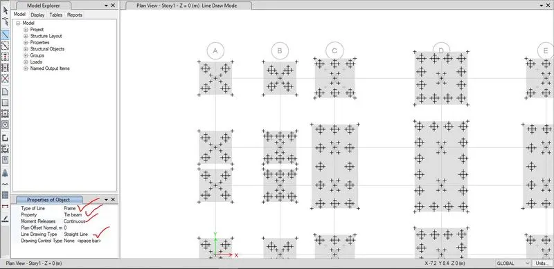
Step-12- After ensuring the shear check and bearing check, the tie beam has been drafted for avoiding differential displacement by using draw beam tool.
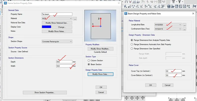
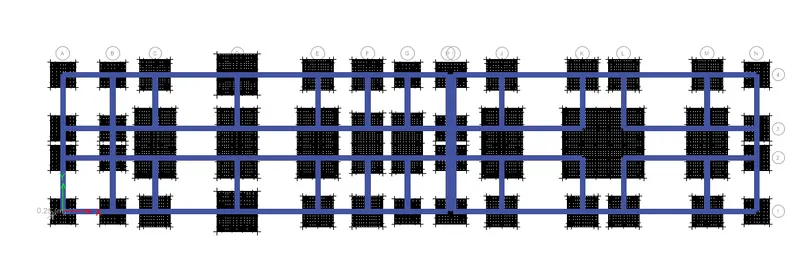
Step-13- then the next step is design. For designing, first of all design strips of both the direction has been created. For this model, for the different size of the pile cap column strips and middle strip has been created.
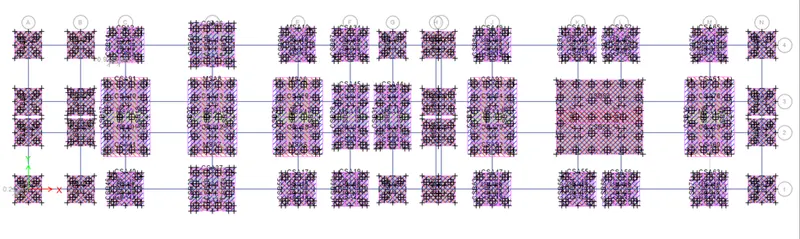
Step-14- After finding of the area of steel, no of bars with proper size and spacing for all the design strip, reinforcement detailing has been drafted in AUTOCAD.
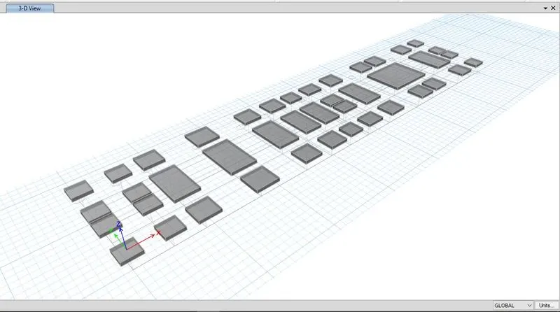
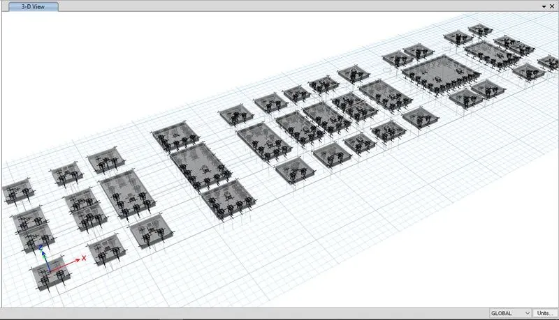
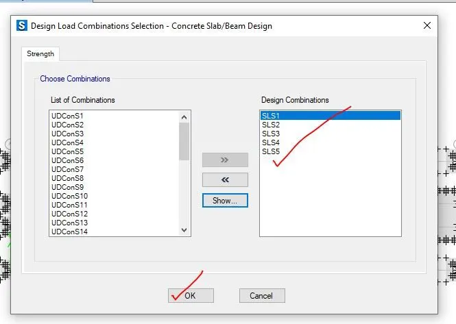
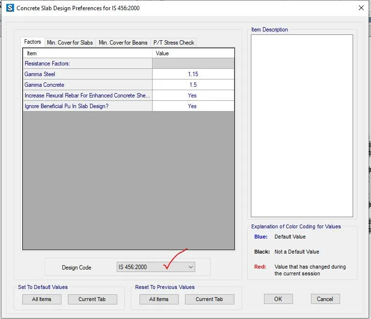
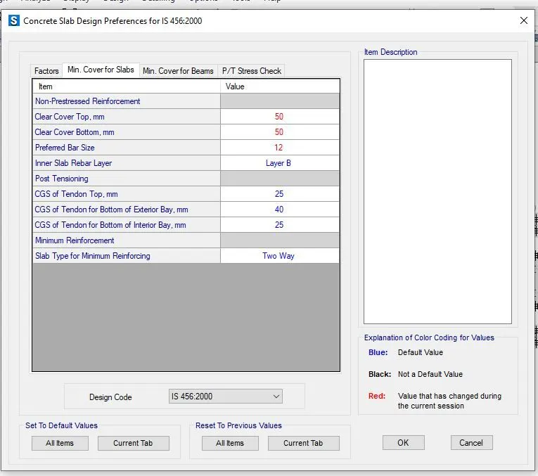
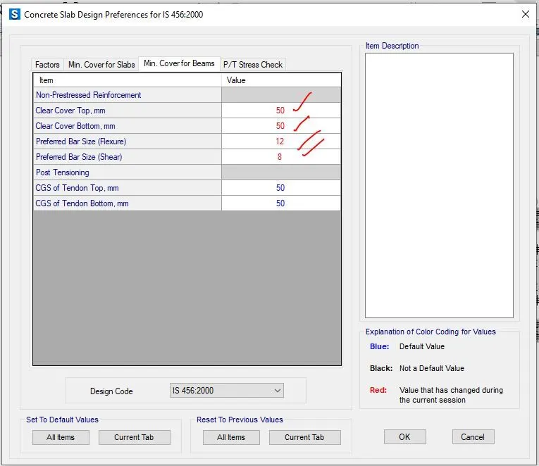
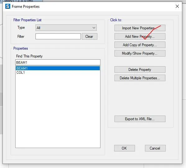
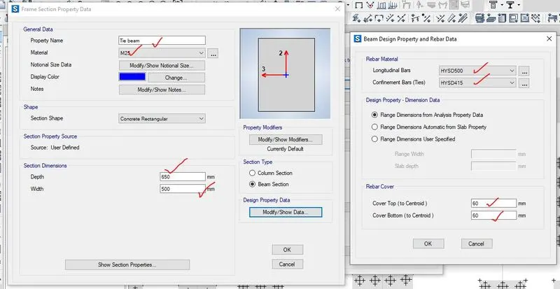
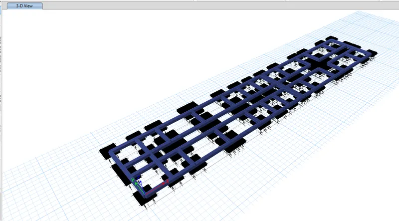
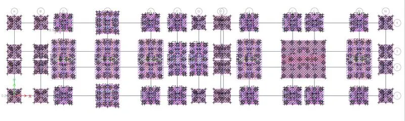
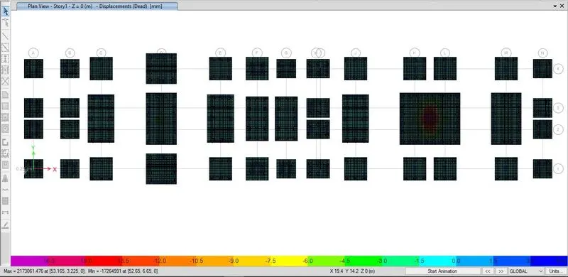
1.3.15 All the step wise screen shots in modelling, analyzing and designing the pile cap and tie beam is given below,
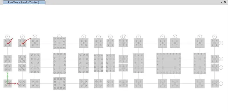
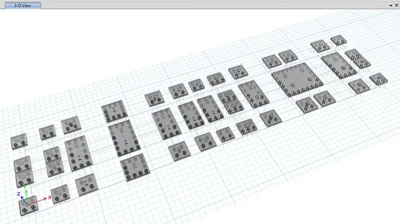
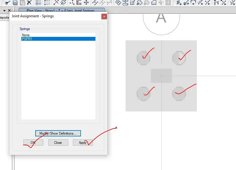
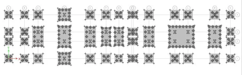
1.3.16 Detailing of pile cap in the hostel block by SAFE
1.3.17 Results and Discussion
- Pile cap longitudinal reinforcement of Layer A and B
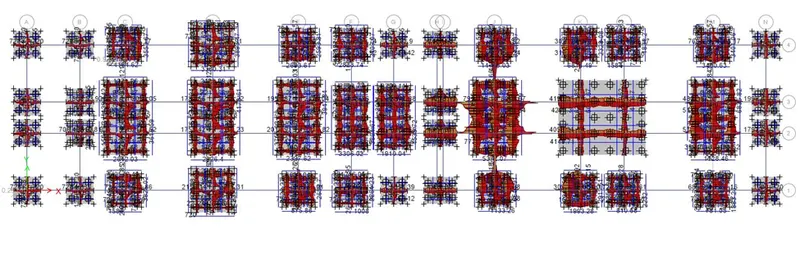
- Pile cap longitudinal reinforcement of Layer A and B at grid B3
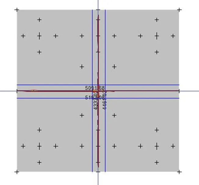
1.3.18 Calculation of bar detailing for pile foundation
For Grid B3,
For strip layer A, max area of steel per unit width for column strip at top= 5091.68mm2
For strip layer A, max area of steel per unit width for column strip at bottom= 519306mm2
For strip layer B, max area of steel per unit width for column strip at top= 4332.02mm2
For strip layer B, max area of steel per unit width for column strip at bottom= 4461.02mm2
For design strip layer A -
Area of steel per unit width= 5091.68mm2i.e. 5100 mm2
Assuming 20mm diameter bar, the numbers of bars= (5100/ ((pie/4)×282))= 8.99 i.e. 9
Area of steel provided= 9× ( pie/4)×282= 5541 mm2
Spacing can be calculated as,
Spacing= (1000/9)= 111.11mm, so provide 100mm spacing,
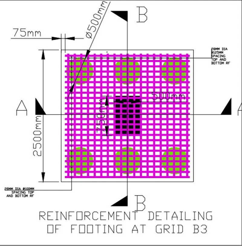
For column strip layer A, provide 28mm diameter @100mm spacing for top and bottom because of nearly same area of steel is required for top and bottom.
For design strip layer b -
Area of steel per unit width= 4461.02mm2.e. 4461 mm2
Assuming 28mm diameter bar, the numbers of bars= (4461/ ((pie/4)×282))= 7.2 i.e. 8
Area of steel provided= 8× ( pie/4)×282= 4926mm2
Spacing can be calculated as,
Spacing= (1000/8)= 125mm, so provide 125mm spacing,
For strip layer B, provide 28mm diameter @125mm spacing for bottom as well top reinforcement.
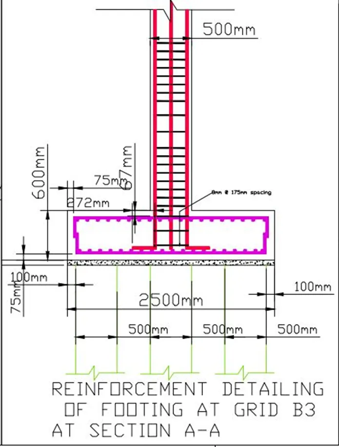
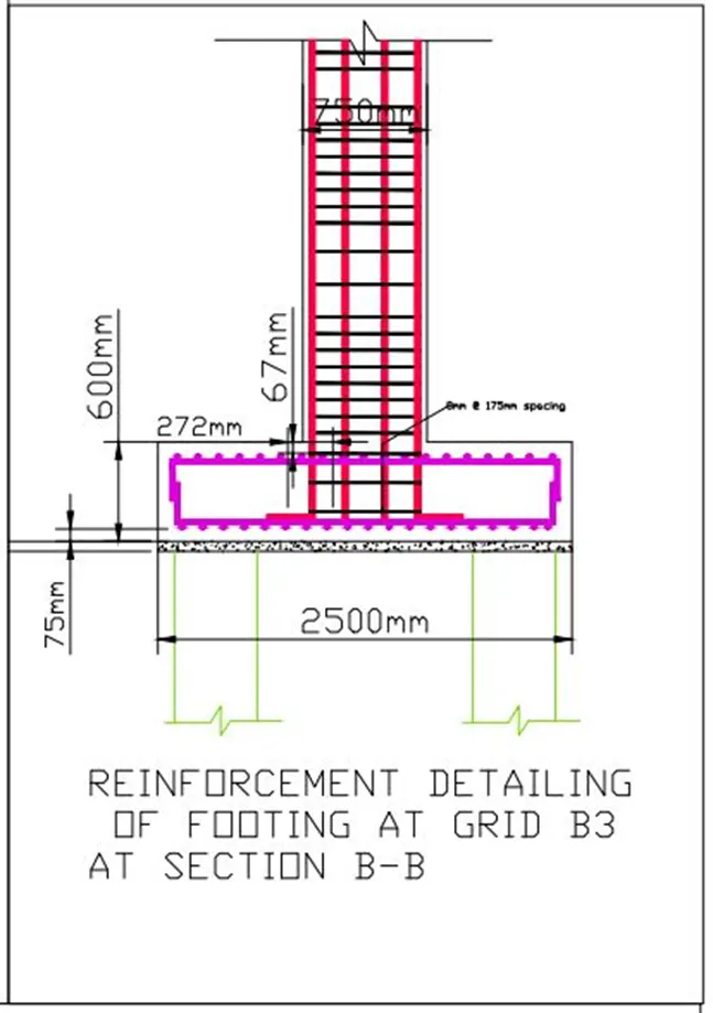
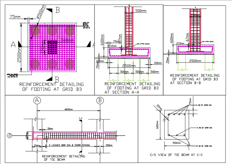
Reinforcement detailing of the pile cap at grid B3 has been drafted by using AUTOCAD which is shown below,
1.3.19 Detailing of tie beam in the hostel block by SAFE
1.3.20 Results and Discussion
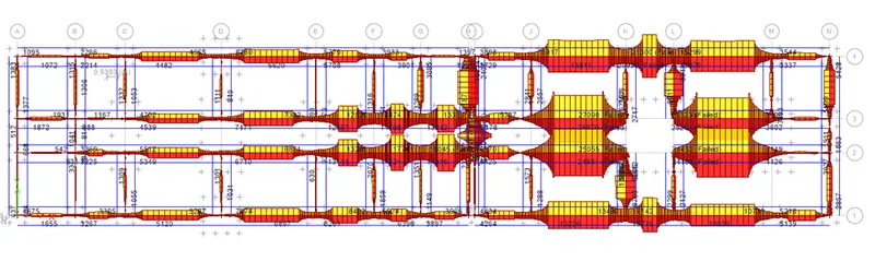
- Tie beam longitudinal reinforcement
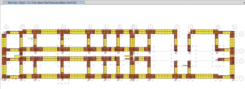
- Tie beam transvers reinforcement
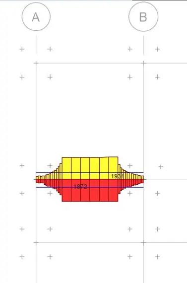
- Tie beam longitudinal reinforcement at GRID A3-B3
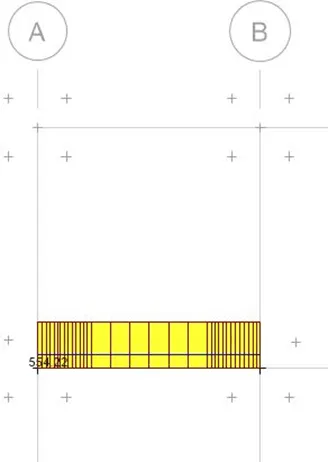
- Tie beam transverse reinforcement at GRID A3-B3
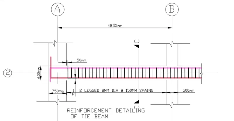
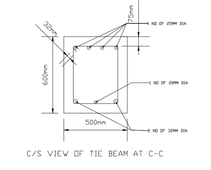
1.3.21 Reinforcement detailing of the tie beam at grid A3-B3 has been drafted by using AUTOCAD which is shown below,
1.4 Note- List of the documents that has uploaded is given below,
- Details reinforcement file i.e.
- hostel_block_detailing_3-beam layout.pdf
- hostel_block_detailing_3-beam rf (2).pdf
- hostel_block_detailing_3-column rf.pdf
- hostel_block_detailing_3-footing layout.pdf
- hostel_block_detailing_3-FOOTING RF.pdf
- dwg
- ETABS file named as Hostel block_5_1.edb
- SAFE file named as Hostel block_pile_cap_6_design_3.fdb