Modelling of 25 storey building with the specified properties using ETABS
1.1 Aim of the Project-
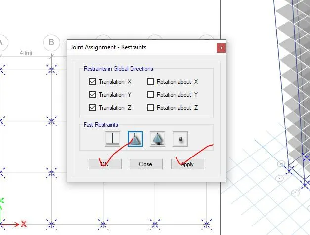
To model and structural analysis of a 25 storey building on ETABS with structural properties as specified below in given data. In which the building have Ground floor or plinth floor level can be taken at a height of 1.5 metres from the base. Each of the successive 25 storeys has a storey height of 3 metres.
1.2 Introduction
25 storey building have Ground floor or plinth floor level can be taken at a height of 1.5 metres from the base. Each of the successive 25 storeys has a storey height of 3 metres.
Given data,
Structural Element Sizes
- Beams : 300 × 400 mm
- Columns : 800 × 800 mm
- Slab : 150 mm thick
Material Properties
- Grade of Concrete : M30
- Grade of Steel Reinforcement Bars : Fe 415
Loading
- Dead Load on beams from infill wall : 10 kN/m (Let us assume the same for roof floor in view of parapet)
- Live load on floor : 3 kN/m2 (Let us assume the same for roof floor)
a) Buildings are assumed to be pinned at the base
b) All columns in all storey are of the same size
c) All beams in all storeys are of the same size
d) Building is located on Soil type-II and in Zone-III. Assume other factors if required.
2.1 Procedure
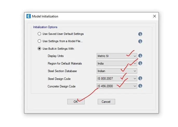
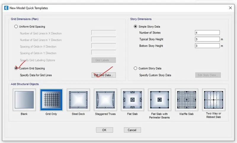
Step 1- after the opening of the ETAB , the new model has been created by using built up setting which is given below,
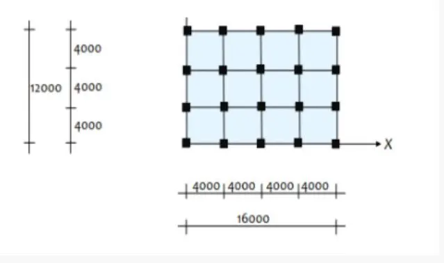
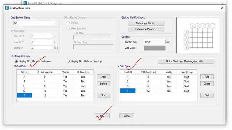
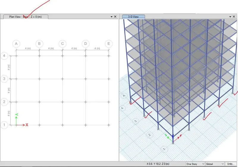
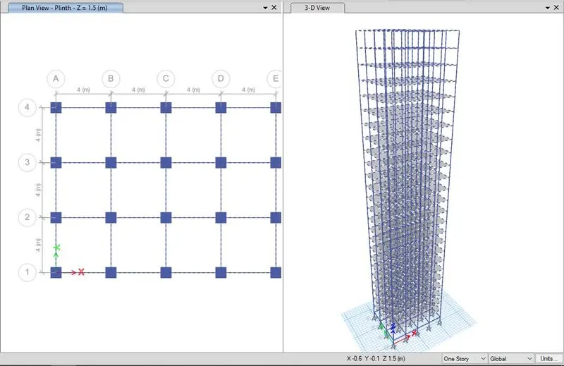
Step 2- Grids has been created by using the custom spacing with edit grid data as per the given data i.e. x coordinate data and y coordinate data with spacing of 4m has been created which is given below,
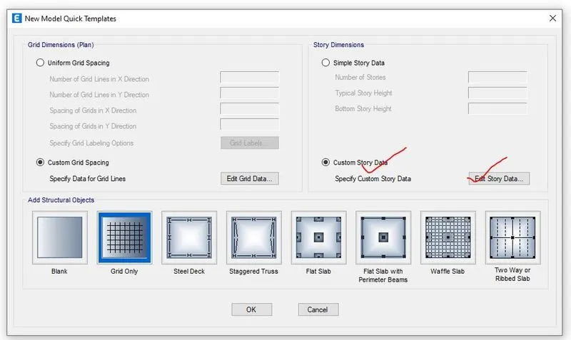
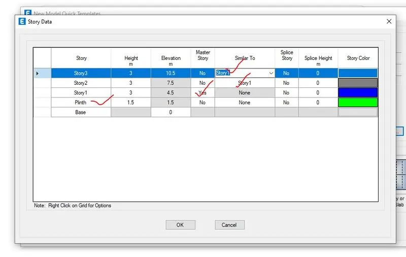
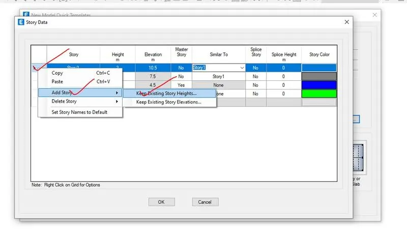
Step 3- After grid formation, story data has been inserted as per the given data i.e. plinth level at 1.5m from the ground level and at 3m the height of story 1 to story 25 has been created by making the story 1 as master story and other story is similar to storey 1 except plinth.
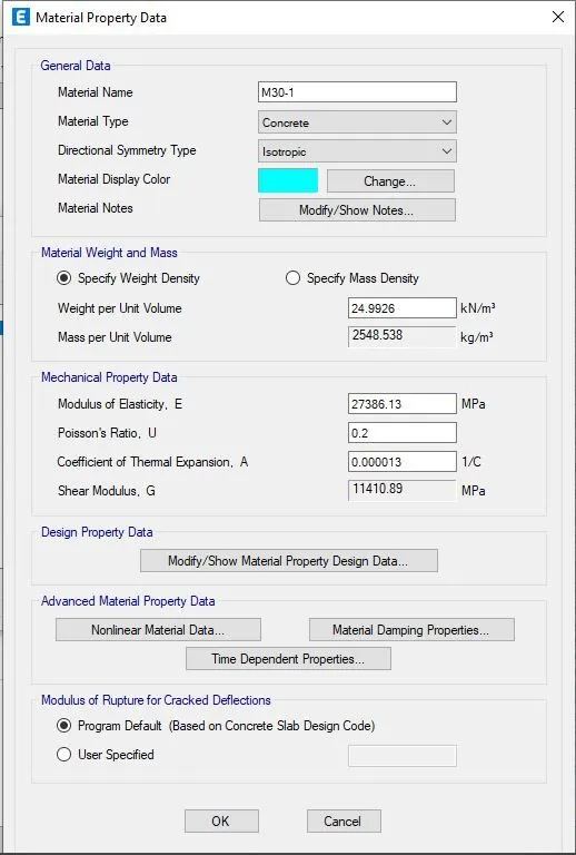
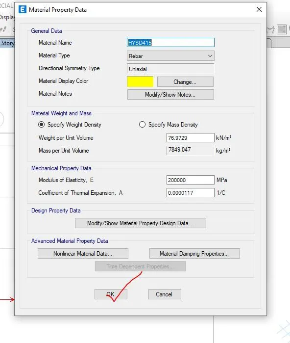
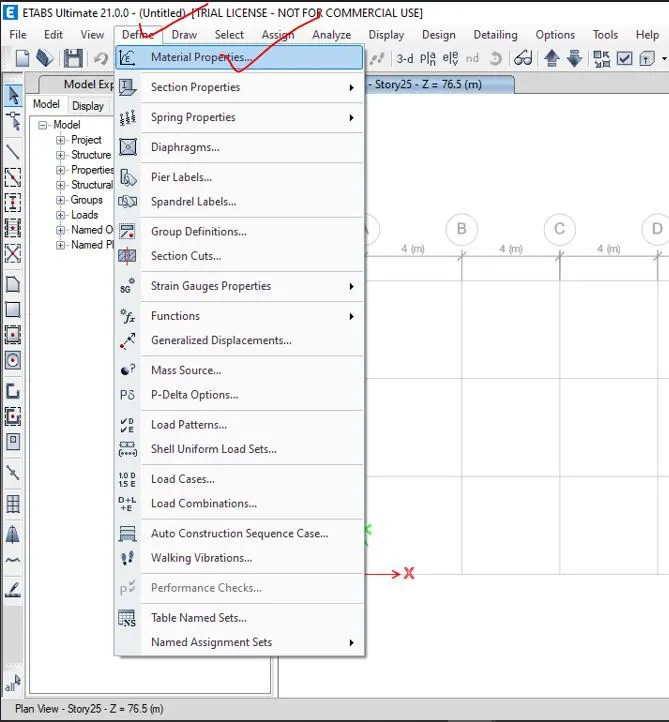
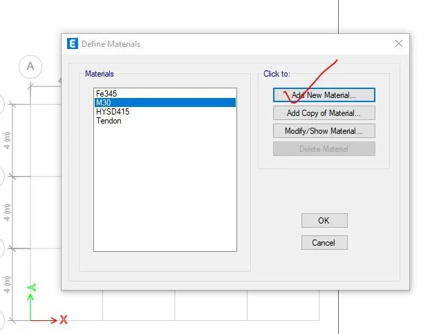
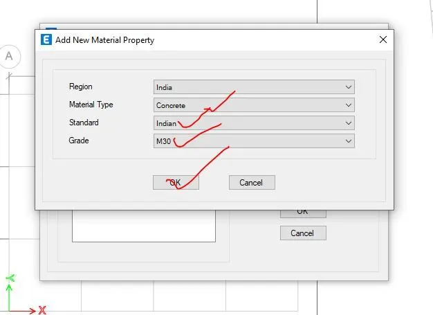
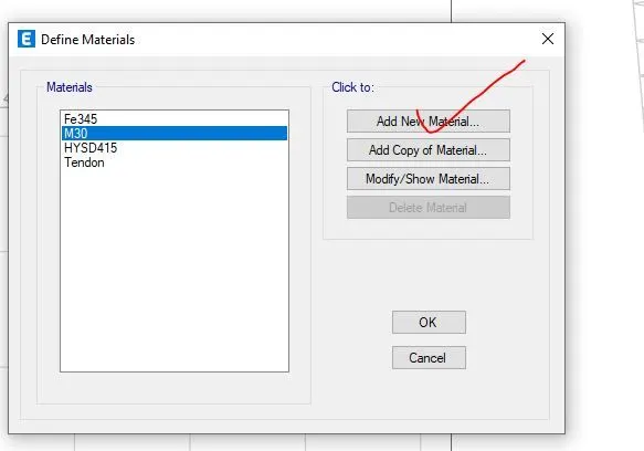
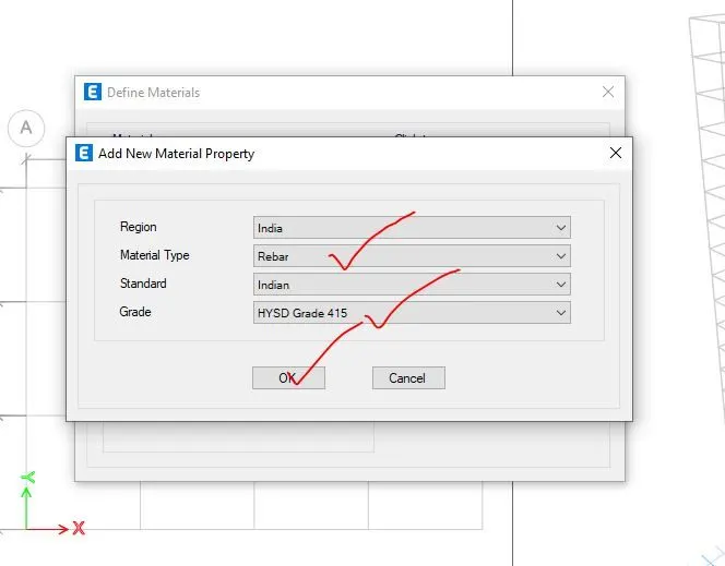
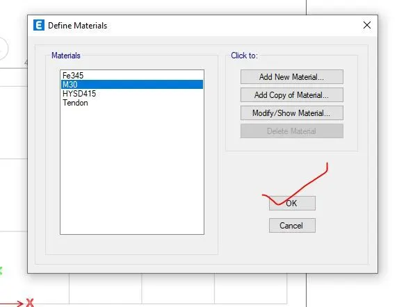
Step 4- After creating grids and story, then the material properties has been defined by clicking on the define option and then define material and then new properties and then a pop-up box will be opened where the concrete and steel has been specified as per the required data.
For this project, concrete of M30 grade and steel as reinforcement i.e. rebar of fe415 which is given below,
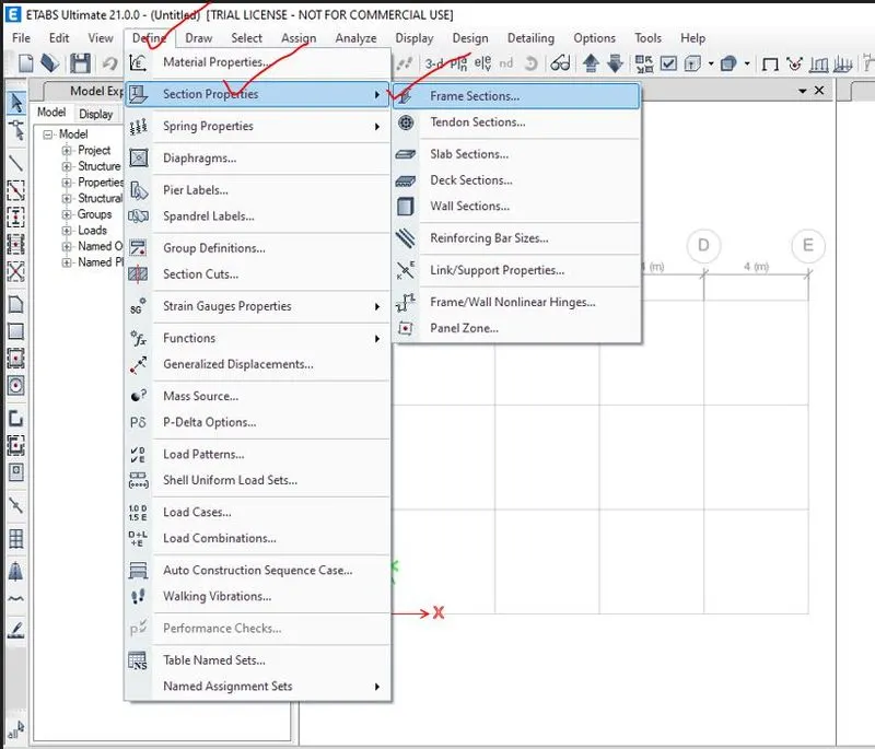
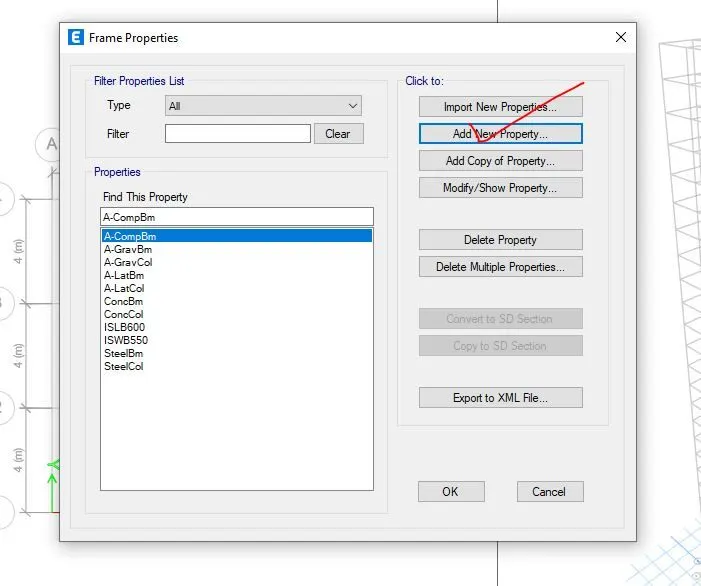
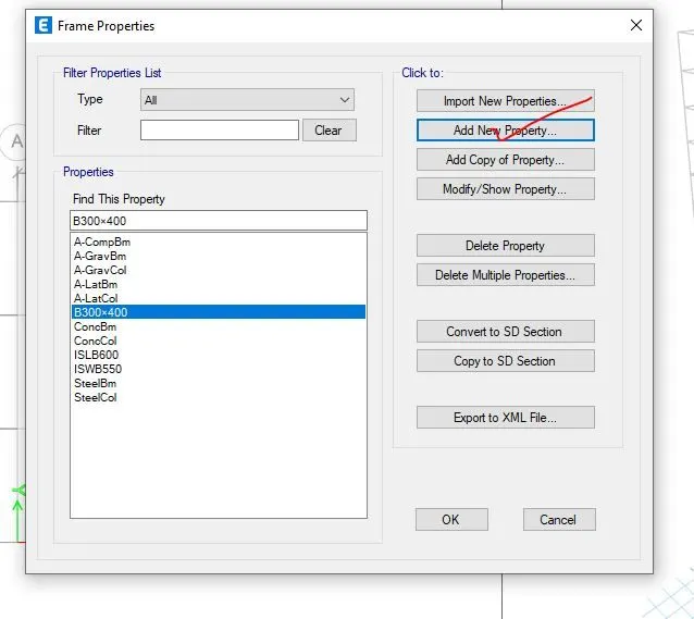
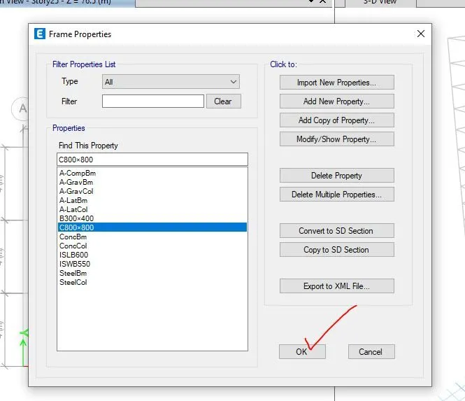
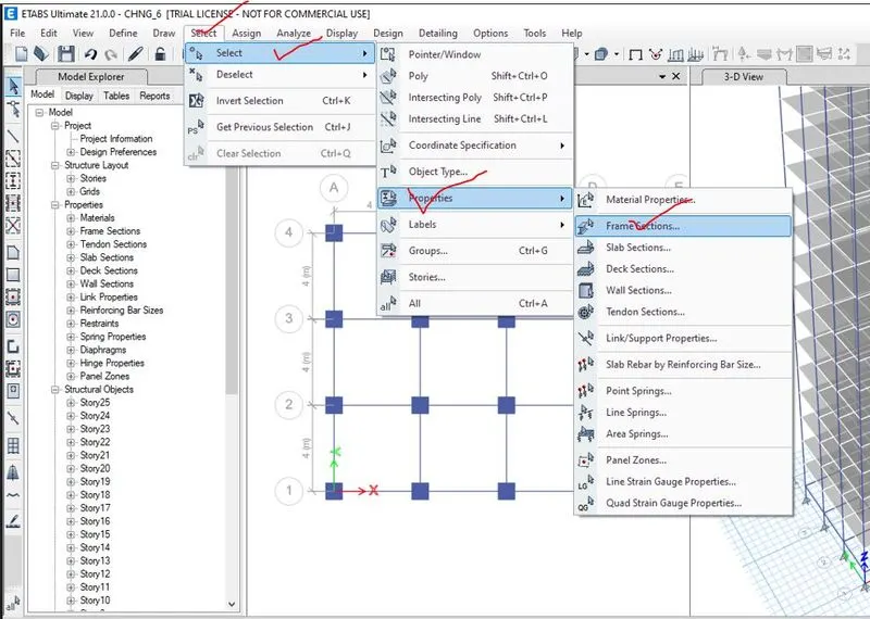
Step 5-After defining the material properties, frame properties of the model has been defined by clicking on the define option and then section properties and then frame properties then a pop-up will be opened.
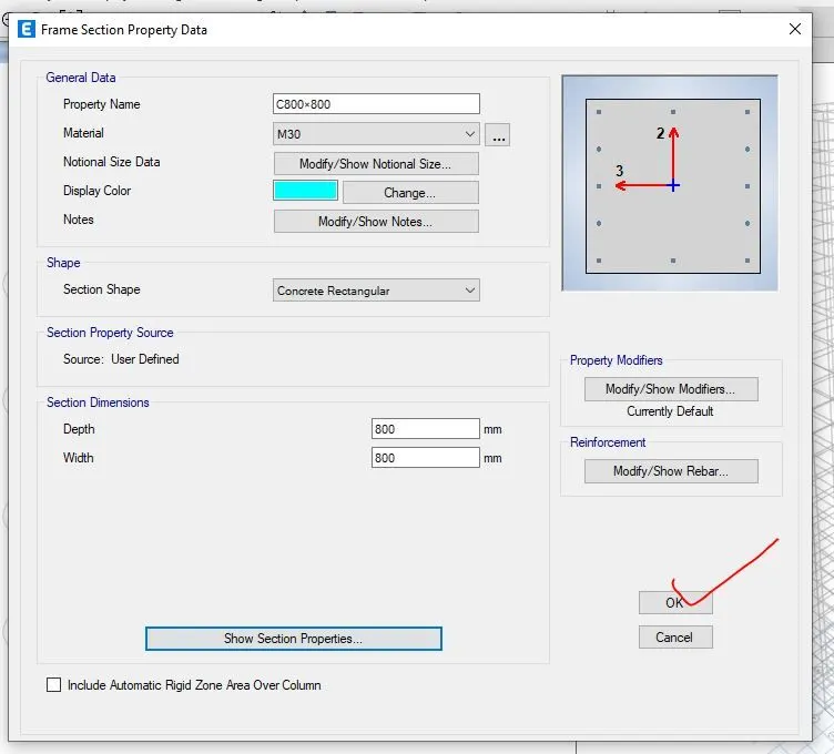
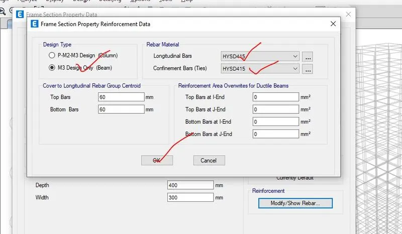
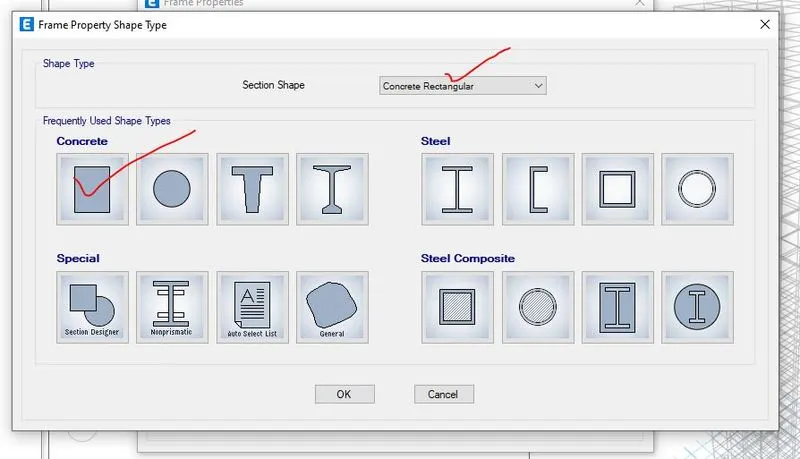
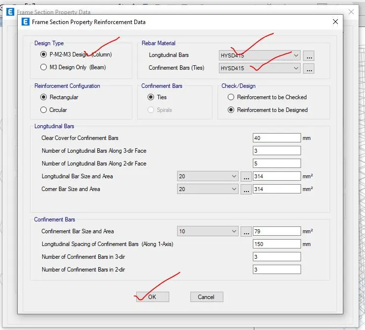
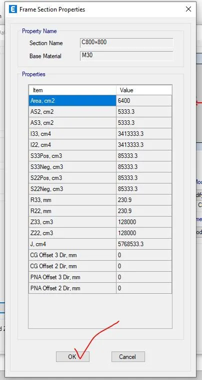
After a pop up box is opened, then by clicking on the add new properties and then specify the concrete rectangular and then rectangular section and then another pop up box frame section propertied data will be opened where properties name, material, section dimension, property modifier and reinforcement details has been assigned.
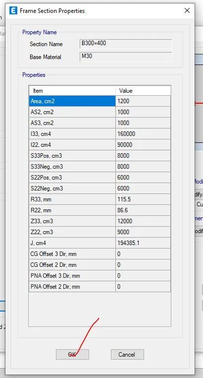
For this project, the data for column as well as beam also has been added that is given below,
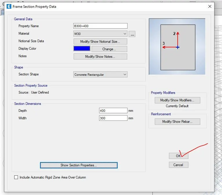
Step 6- Same procedure has been followed for adding of beam sectional properties and data that has been used in this project is given below,
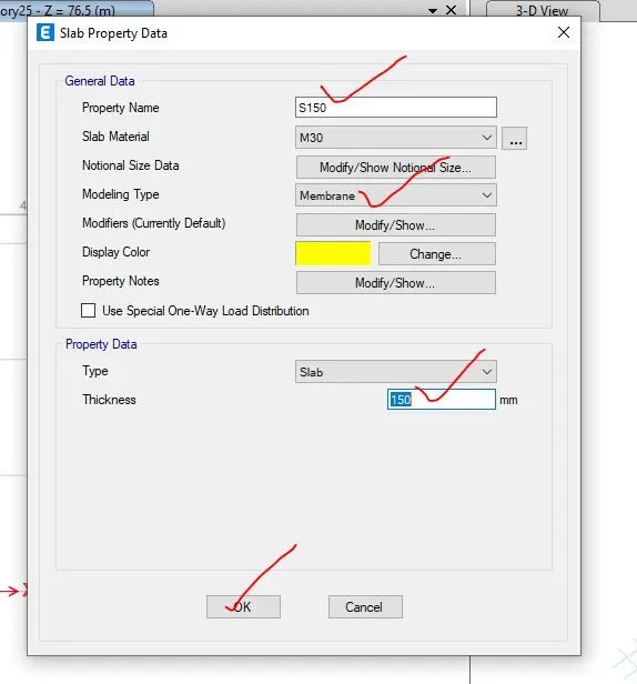
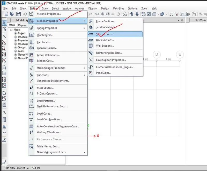
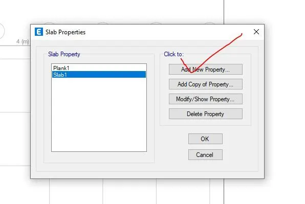
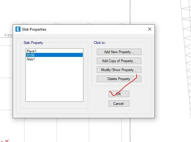
Step 7- For defining of the section properties of slab, go to the define and then clicking on section properties and then click on the slab definition, and then as per the given data which has been shown below,
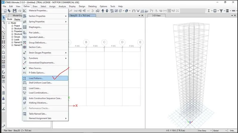
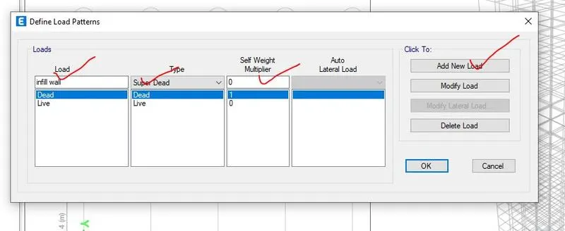
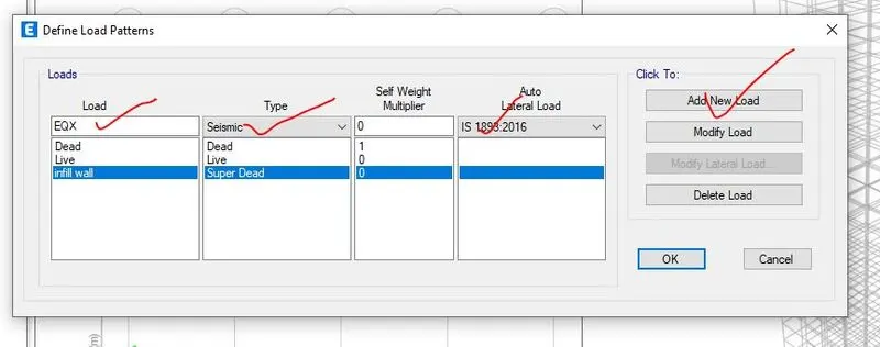
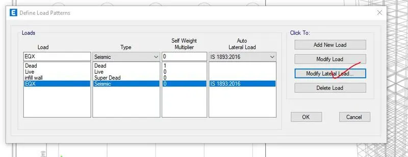
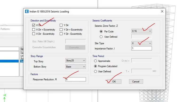
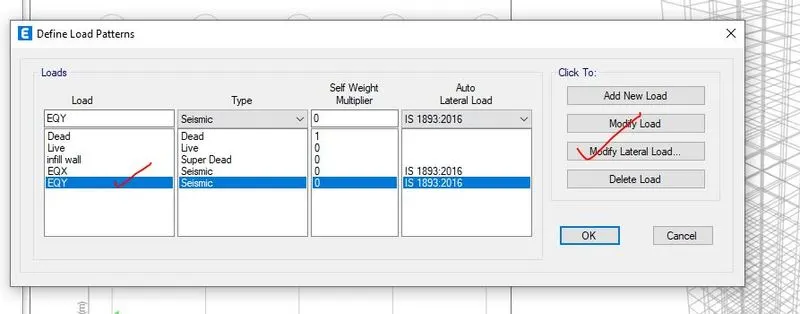
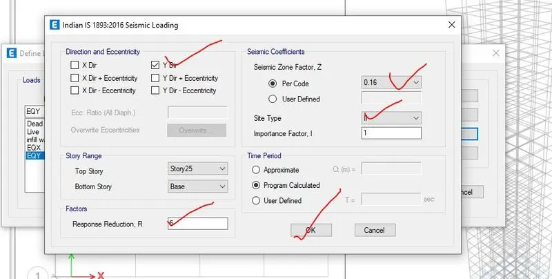
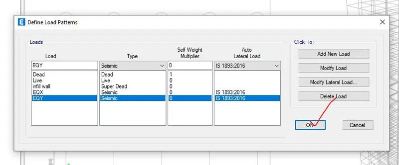
Step 8- Now the load pattern has been defined I.e. wall load, live load, dead load and seismic load i.e. EQX (in x direction) and EQY (in y direction) with supporting of IS code of 1893:2016.
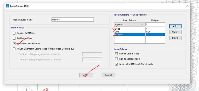
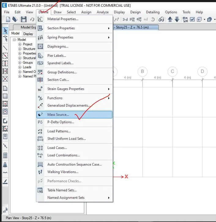
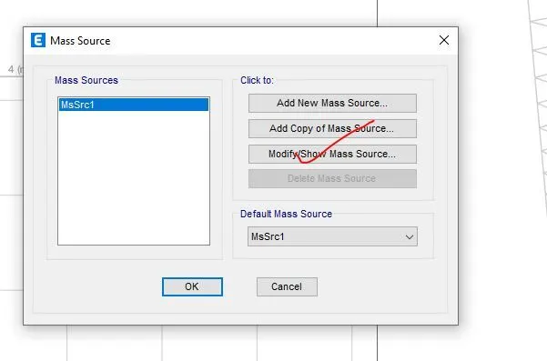
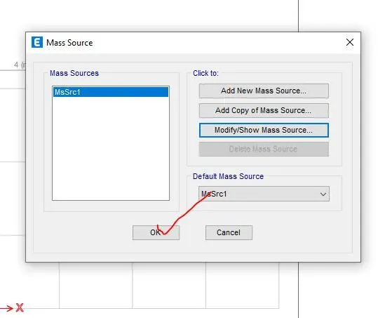
Step 9- After defining the load pattern, mass sources data has been added by clicking on the define option and then mass source where % mass has been defined for dead load, live load or imposed load and for wall i.e. super dead load which is given below,
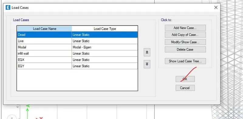
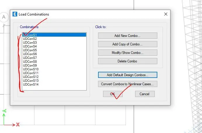
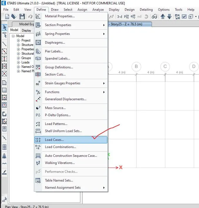
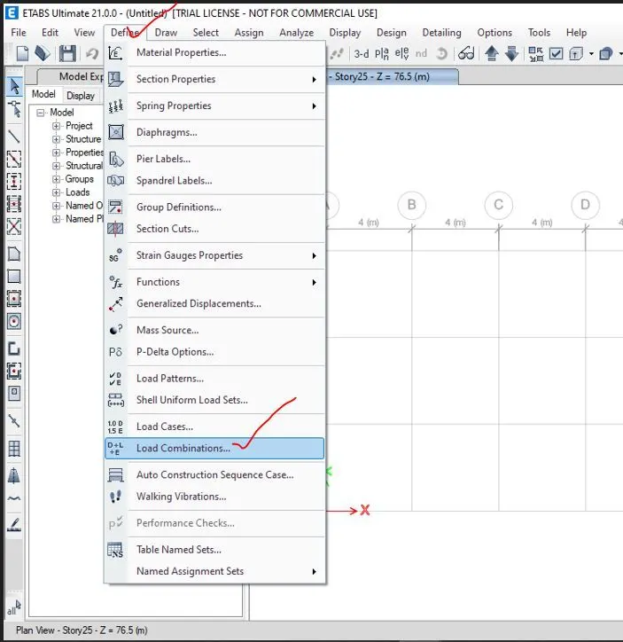
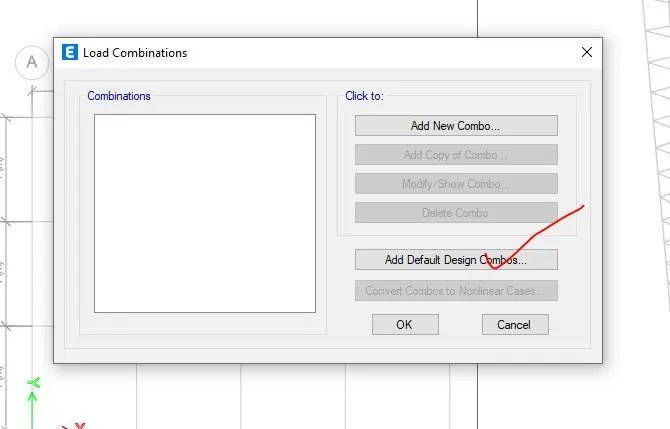
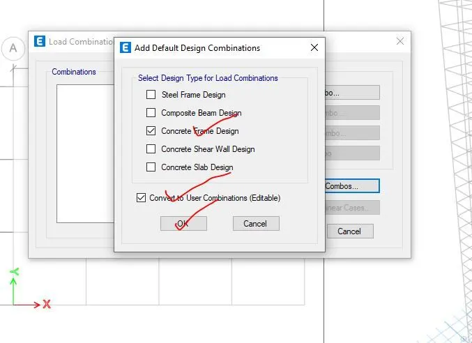
Step 10- check for the load cases which will be found on the define option and then the load combination is added from define option and by clicking on add default design combo for concrete frame structure which is given below,
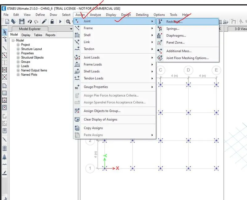
Step 11- after defining the material properties, section properties and loads, now all the section has been assigned to the required places.
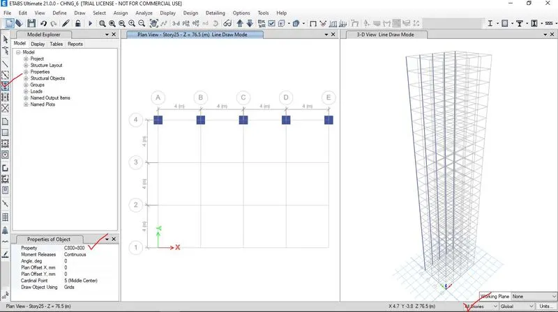
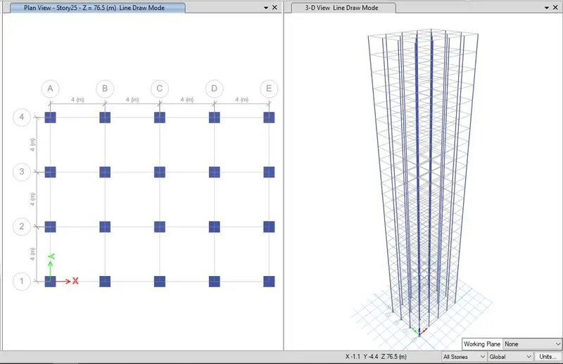
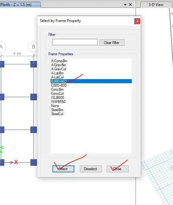
For column, by accessing the quick draw column and the required column size has been chose and the selected column has been assigned to the required places and all the storey must be selected.
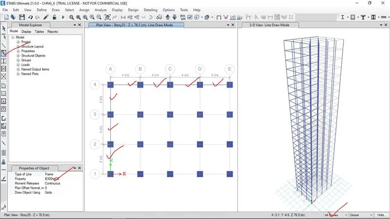
Same procedure has been followed for beam and slab: for beam, quick draw beam and for slab, quick draw slab/ floor has been chosen.
But, for slab only similar storey has been selected as the slab has not been assigned to plinth level.
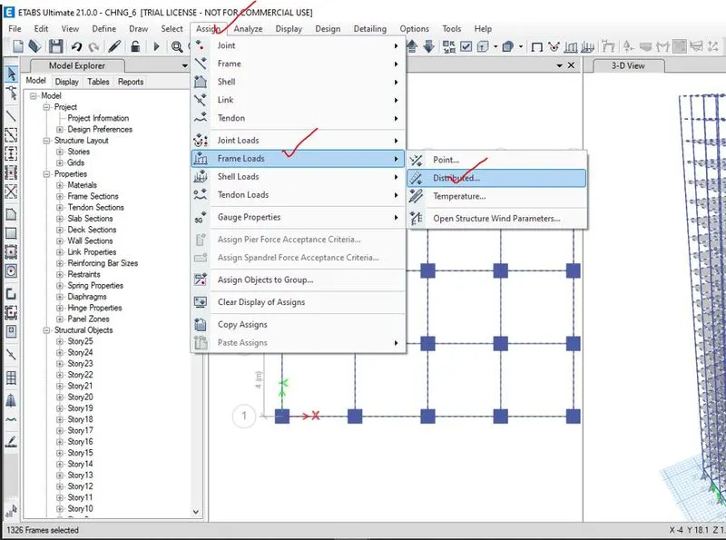
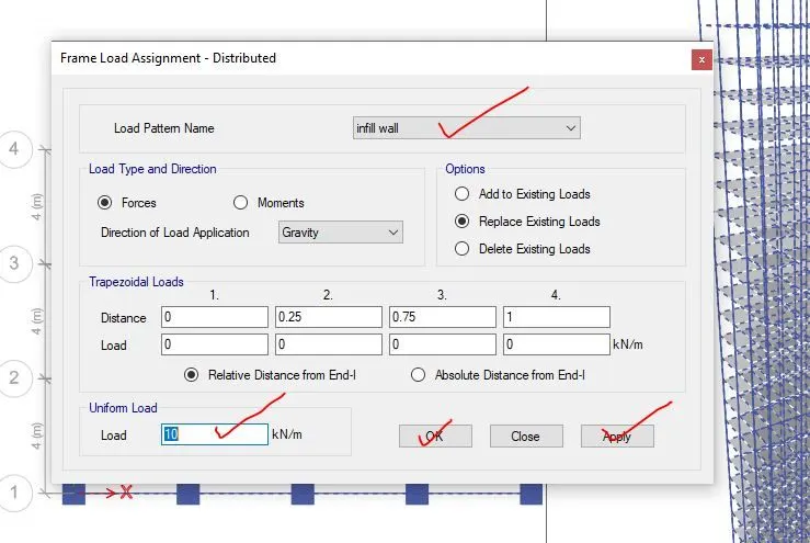
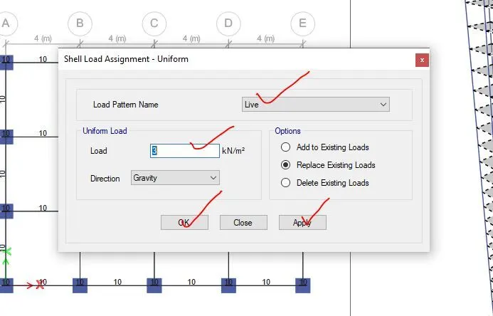
Step 12-After assigning the frame properties, now the load i.e. dead load, live load or imposed load and wall load has been added to the frame structure.
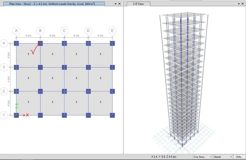
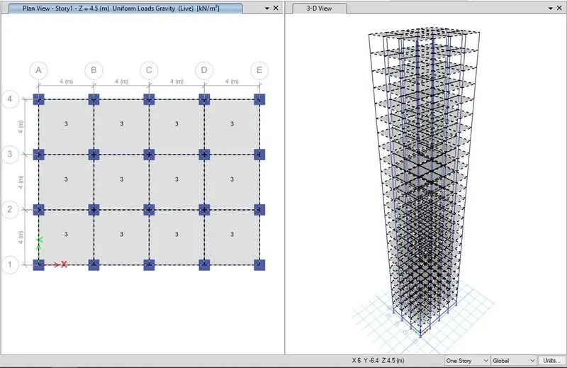
Here in this project, live load for 3kn/m2 is applied on the slab and wall load of 10 Kn/m2 is applied on the beam frame.
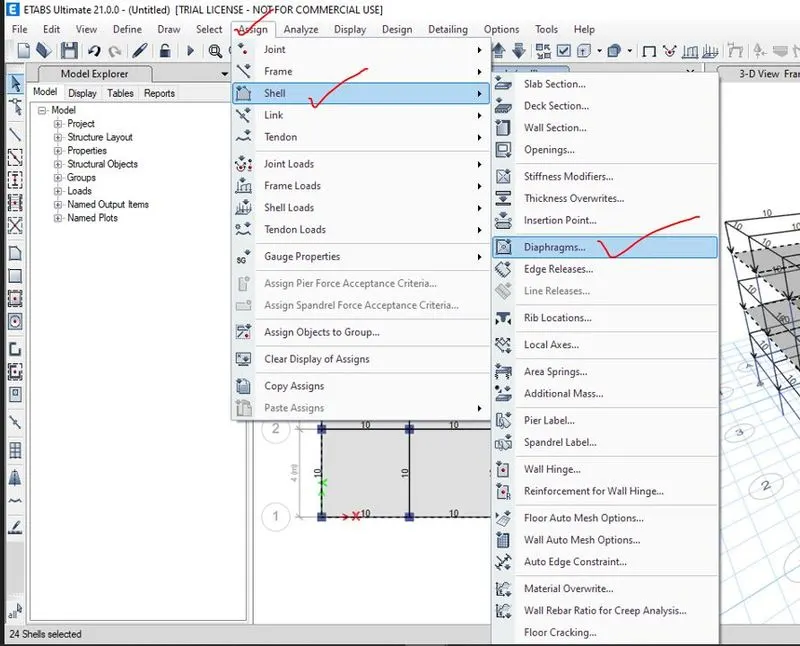
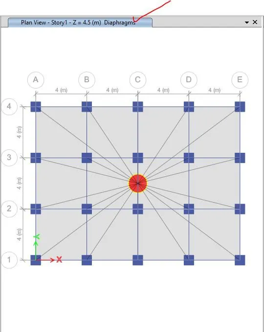
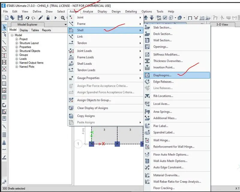
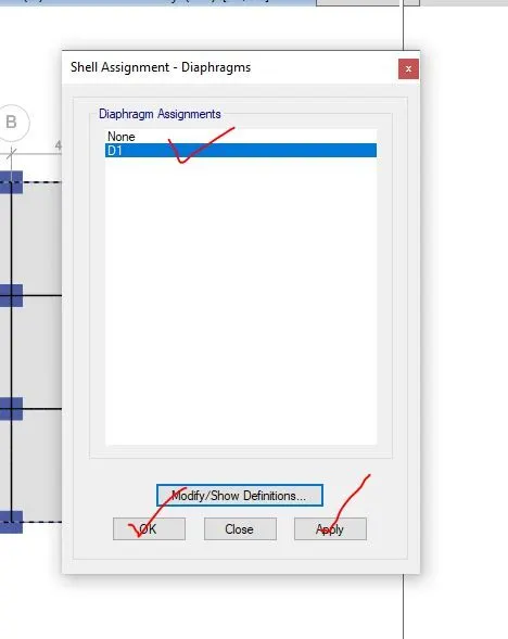
Step 13- Assigning of diaphragms on the slab of all assigning slab for making mass of all the slab should be concentered on the CG of the slab.
First of all the slab has been selected and then by clicking on the assign option and then shell and then diaphragms has been selected which is given below,
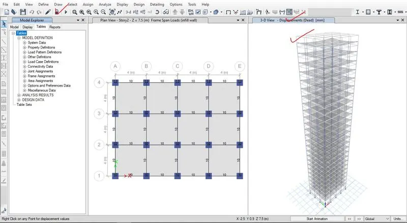
Step 14- Now using the F5 bottom or by directly by clicking on the run option; this model is analyzed.
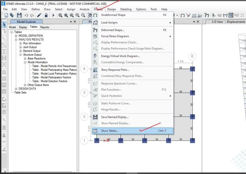
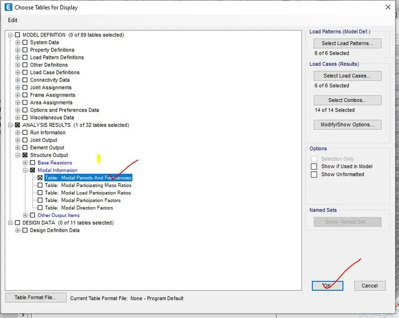
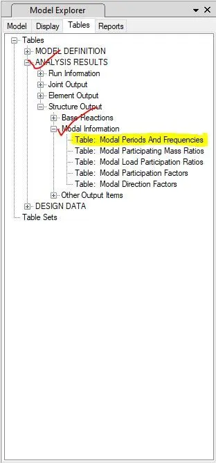
Step 15- After model is analyzed, the model properties and frequency has been found which steps has been shown below,
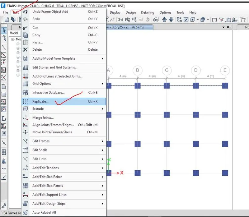
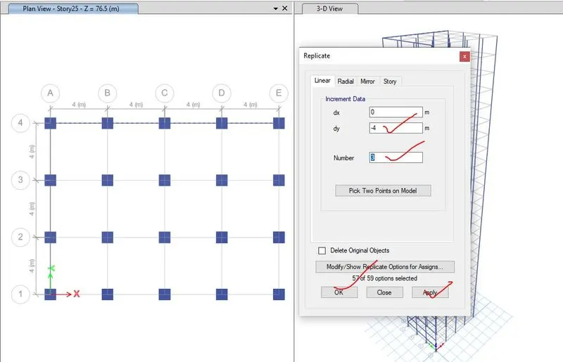
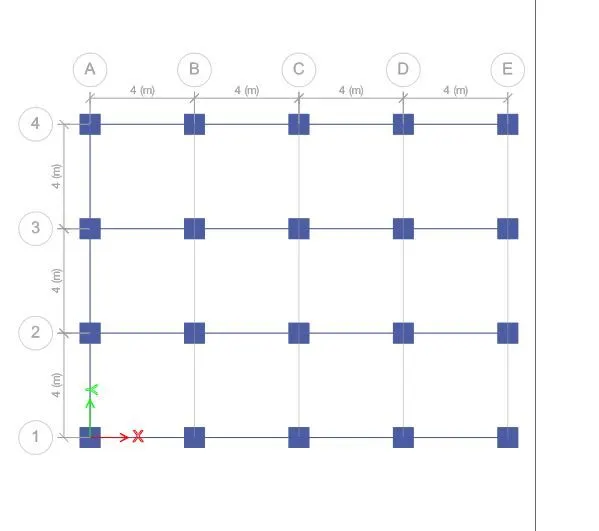
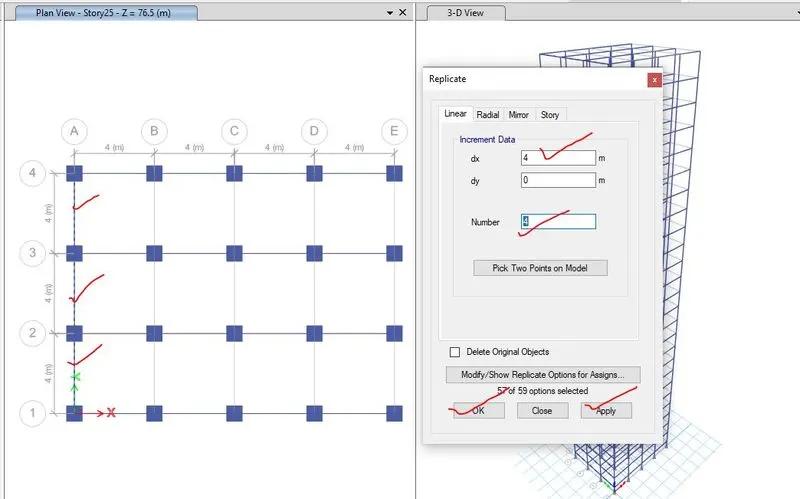
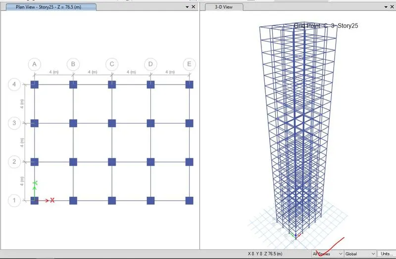
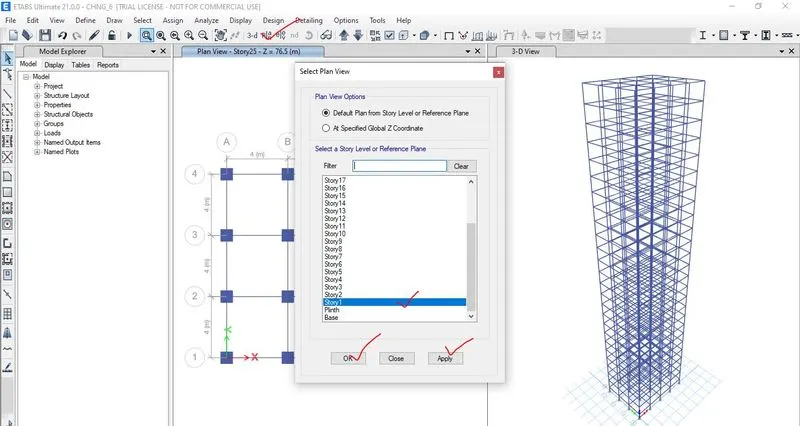
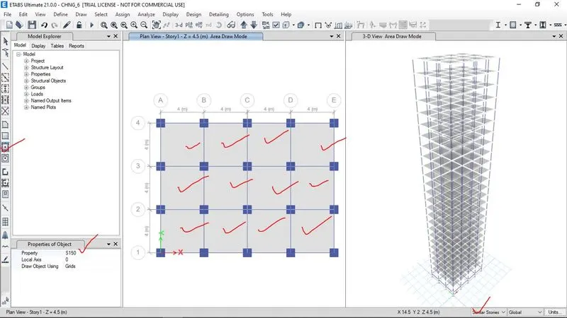
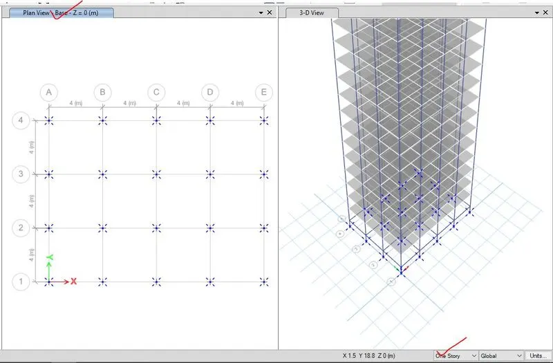
2.2 All the step wise screen shot that has been taken in making the structure and in analyzing the structure, have been given below,
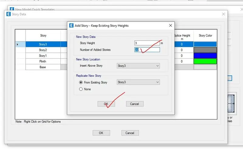
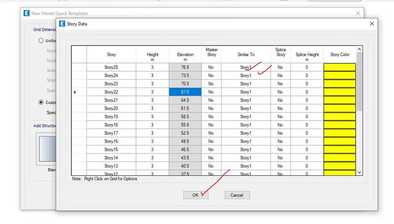
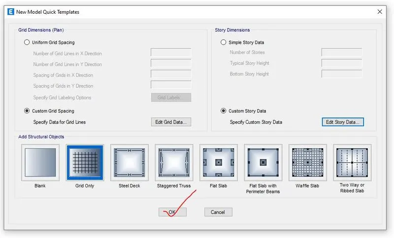
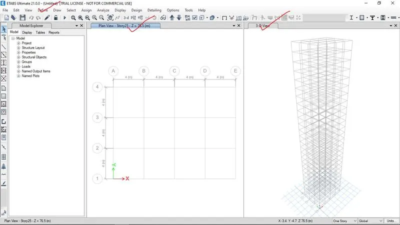
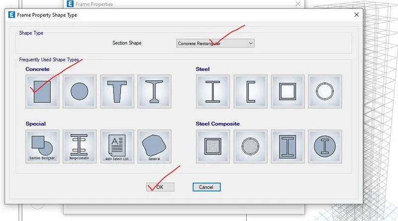
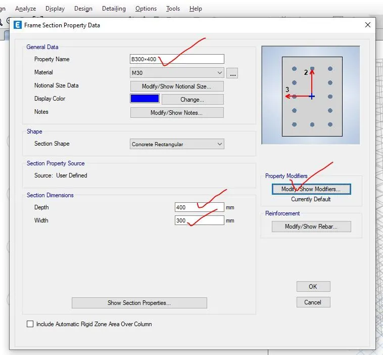
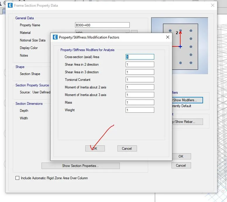
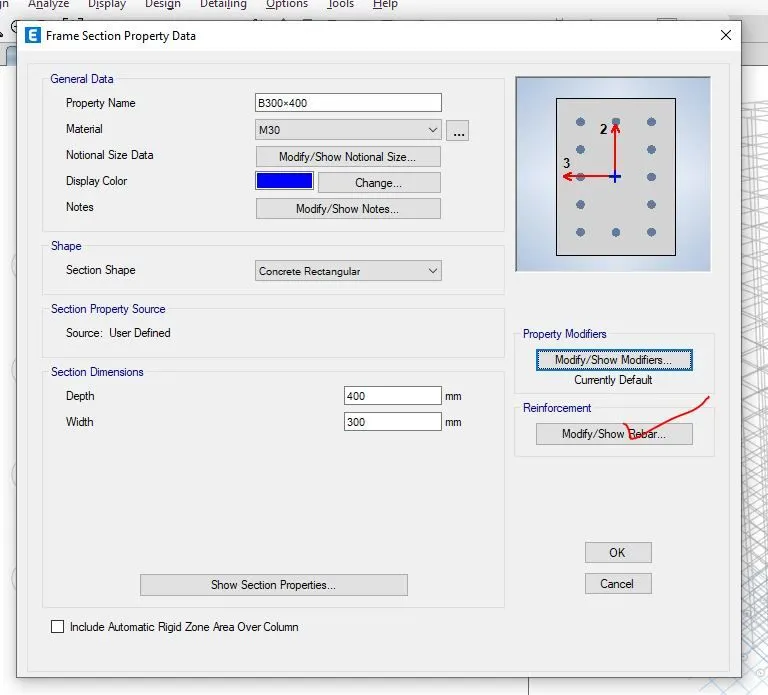
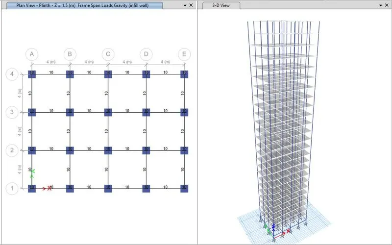
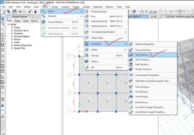
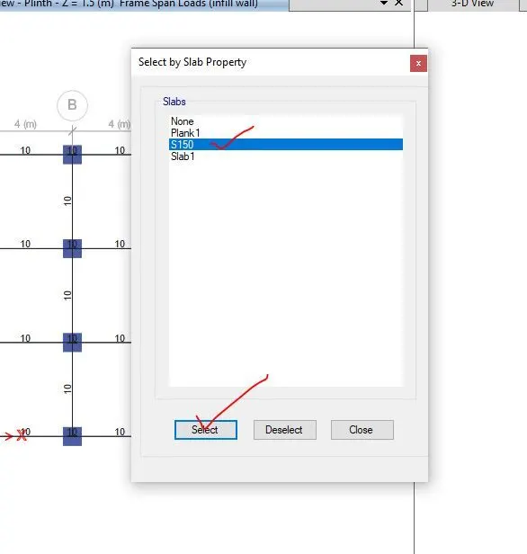
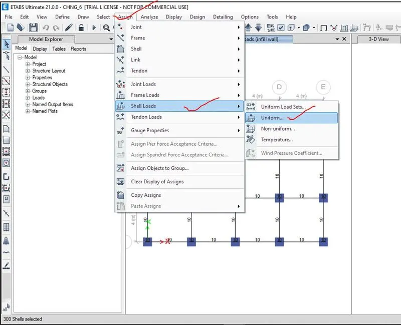

3.Results and discussion-
3.1 Results-
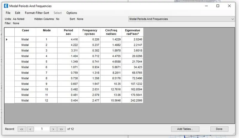
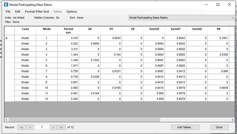
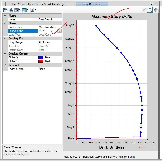
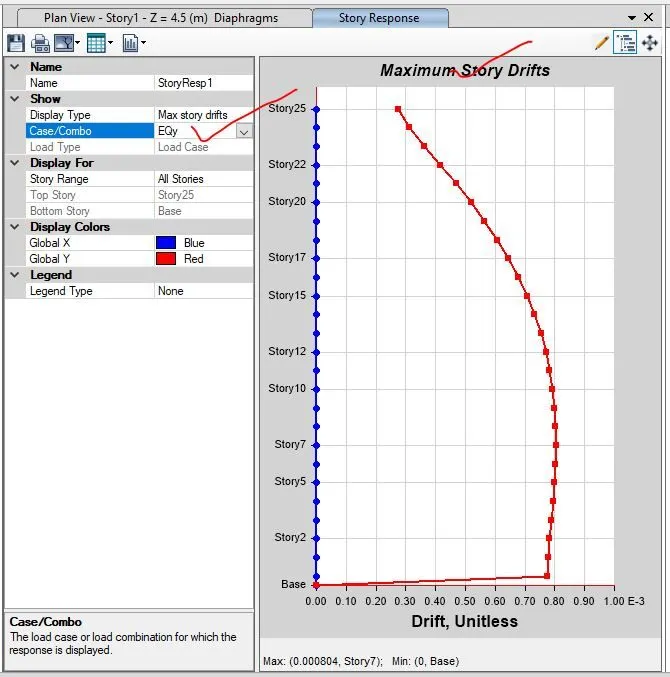
After the model is analyzed, the modal periods and frequencies and storey drift in X and Y direction for seismic load has been found which is given below,
3.2 Discussion-
|
Criteria |
Direction |
Desirable solution |
Exercise results |
|
Fundamental translational natural period |
X direction |
4.4 seconds |
4.416 seconds |
|
Y direction |
4.2 seconds |
4.222 seconds |
|
|
Torsional irregularity |
IS 1893-2016 (part-1) Table-5 |
Torsional mode time period should be lesser than X and Y direction time periods. |
YES |
|
Vertical Irregularity |
IS 1893-2016 (part-1) Table-6 clause-7 |
First three modes together should contribute at least 65% in mass participation factor in each principle direction. |
YES |
|
Fundamental lateral natural periods in two principle place directions are away from each other by least 10%. |
NO |
||
|
Inter storey drift |
IS 1893-2016 (part-1) clause-7.11.1.1 |
Storey drift shall not exceed 0.004 times the storey height for base shear with no load factors (4×10⁻³). |
YES |
3.3 NOTE-
The results in modelling and analysing of the building of 25 stories as per the given data by using ETAB i.e. the .edb file named as Chng_6, has been uploaded below.