Structural dynamics
1. Differentiate Static analysis and Dynamic analysis with proper representing pictures.
--------------------------------------------------------------------------------------------------------
Ans- Difference between static analysis and dynamics analysis
- The term ‘dynamic’ simply means ‘time varying’. A dynamic load is one, the magnitude, direction, or point of application of which varies with time i.e. earthquake and wind load. The structural response to a dynamic load, i.e., the resulting deflections or stresses, is also time dependent or dynamic.
Whereas the term static mean it does nor varying with time. The static load has the magnitude, direction or point of application of which does not vary with time for example dead load, live load on structure.
- In the dynamic analysis, the equation of the motion is used to find the unknown and in case of the static analysis, the equilibrium equation is used to find the unknown reaction.
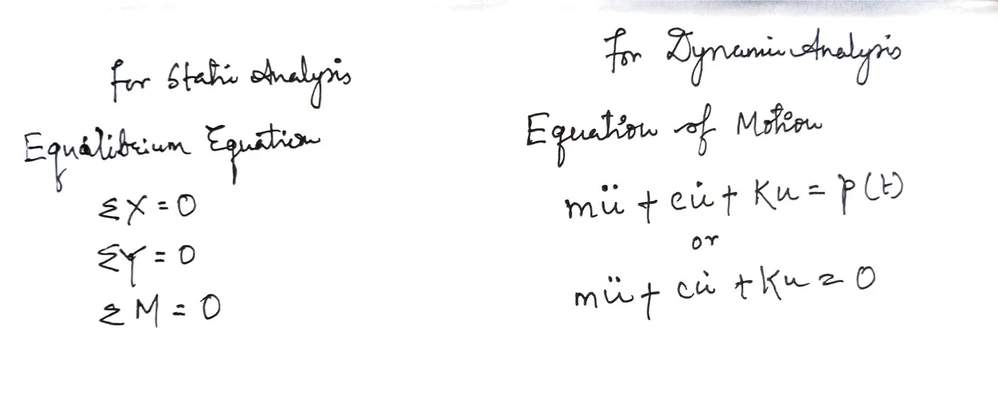
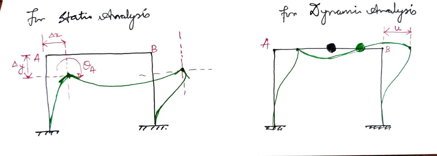
- In static analysis it is assumed that time variation is neglected where as in dynamic analysis time variation is considered.
- In case of static analysis, more degree of freedom is necessary is required to define the stiffness properties for the structure and for dynamic analysis only one degree of freedom i.e. lateral displacement is required to define the structural properties.
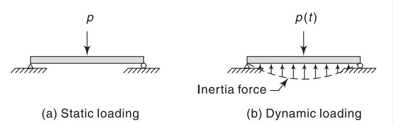
- In a static analysis, a separate solution is required at each instant of time for the entireduration of the earthquake. When a dynamic load p(t) is applied to a structure, e.g.,on a simple beam the resulting displacements are associatedwith accelerations that produce inertia forces resisting the acceleration.
------------------------------------------------------------------------------------------------------------------------
2. Explain the following with relevant force-displacement graph,
- Elastic behavior
- Inelastic behavior
- Plastic behavior
- Non-linear Inelastic behavior
--------------------------------------------------------------------------------------------------------------------------
ANS-
a. Elastic behaviour
- In dynamic analysis, when the load is applied on the structure, structure starts deforms linearly up to an extent and when the load is unloaded, it regains its original shape and size or comes to its original place in the same manner as its linearly. This type of behaviour is called as elastic behaviour.
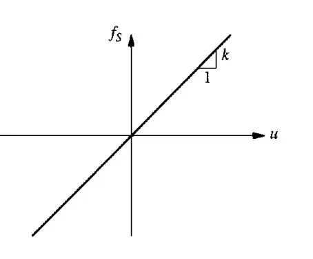
- For linear system the relationship the lateral force fs and resulting deformation as u is linear, that is
Fs= k* u
where k is the lateral stiffness of the system.
- Elastic behaviour with respect to force displacement graph.
-
- In the above graph, it has been shown that when lateral force fs is increasing then the displacement is also increasing linearly and the slope is defined as stiffness.
b. Inelastic behaviour
-
- In inelastic system, the force deformation relation under cyclic loading are shown below, it is observed from the graph that when loading the curve is linear up to elastic limit and after elastic limit the relation curve is non-linear after which is after unloading the structure does not regain its original shape and size and not in the same shape, it follows the hysteresis curve and under reloading the initial lateral force is changed.
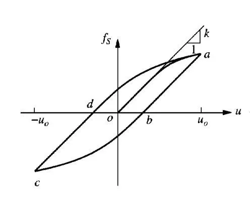
- Force corresponding to deformation is no single valued and depends on history of deformations and deformation is increasing or decreasing.
c. Plastic behaviour
- Plastic behaviour come in to picture after yielding of steel, after elastic limit. It is non-linear behaviour of the structure under cyclic loading.
- The structure under loading after elastic limit, it deforms up to an extent and restrain the stress on the structure and after increasing of the load structure after sometime it utilizes it all the flexural strength and form a hinged behaviour, called plastic hinged.
- Plastic behaviour is same as non-linear inelastic behaviour.
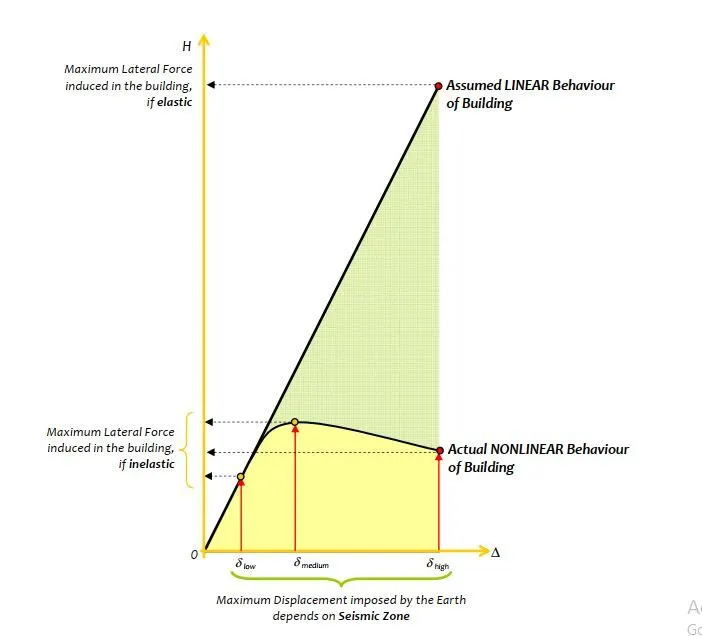
- Comparison of inelastic and elastic behaviour has been shown below,
d. Non-linear inelastic behaviour
- Non-linear inelastic behaviour of the dynamic cyclic loading is same that of inelastic behaviour discussed above.
- In non-linear inelastic system, the force deformation relation under cyclic loading are shown below, it is observed from the graph that when loading the curve is linear up to elastic limit and after elastic limit the relation curve is non-linear after which is after unloading the structure does not regain its original shape and size and not in the same shape, it follows the hysteresis curve and under reloading the initial lateral force is changed.
- Force-displacement graph of non-linear inelastic system is given below,
----------------------------------------------------------------------------------------------------------------------
3. Explain Mass, Stiffness & Damping components in the equation of motion.
---------------------------------------------------------------------------------------------------------------------
Ans-
Equation of the motion for an multi degree of freedom system subjected to external dynamics forced p(t)j where j= 1 to n.
FI + FD +FS =p(t) 
Where m= mass, k= stiffness and c= damping constant
This is a system of n ordinary differential equation governing the displacement due to applied forces. The equation of the motion is the multi degree of freedom equivalent of a single degree of freedom system, each scalar term in the SDF equation has become a vector or a matric of order n and the number of DOFs in MDF system i.e. mass matrix, damping matrix and stiffness matrix.
Mass component in equation of the motion
- In finding the inertia forces for dynamic load, mass component helps in analysing the inertia forces. In general, for lumped mass idealization or concerted at the noses of the discretised structure and it is a diagonal matrix a symmetric matrix also.
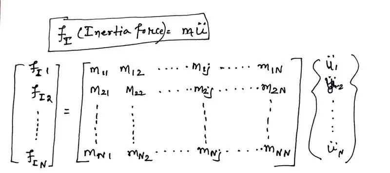
Where mj is the lumped mass associated with jth translational DOF and mjj is equal to zero for rotational DOF. The rotational inertia has negligible influence on the dynamics of structure.
[m] = mass matrix
mij= mji
- The mass representation can be simplified for multi-story building because of the constraining effects of the floor slabs.
- Each floor diaphragm is usually assumed to be rigid in its own plane but is flexible in bending in the vertical direction which is reasonable representation of the true behaviour of several types of floor system.
Stiffness component in equation of the motion
- In the equation of the motion, k represent the stiffness for SDF and [k] represent the stiffness matrix for MDF and “ku” represent the resisting force offered due to stiffness.
- The external forces Fs on the stiffness component of the structure can be related to the resulting displacement.
- For linear systems this relationship can be obtained by the method of superposition and the concept of stiffness influence coefficient.
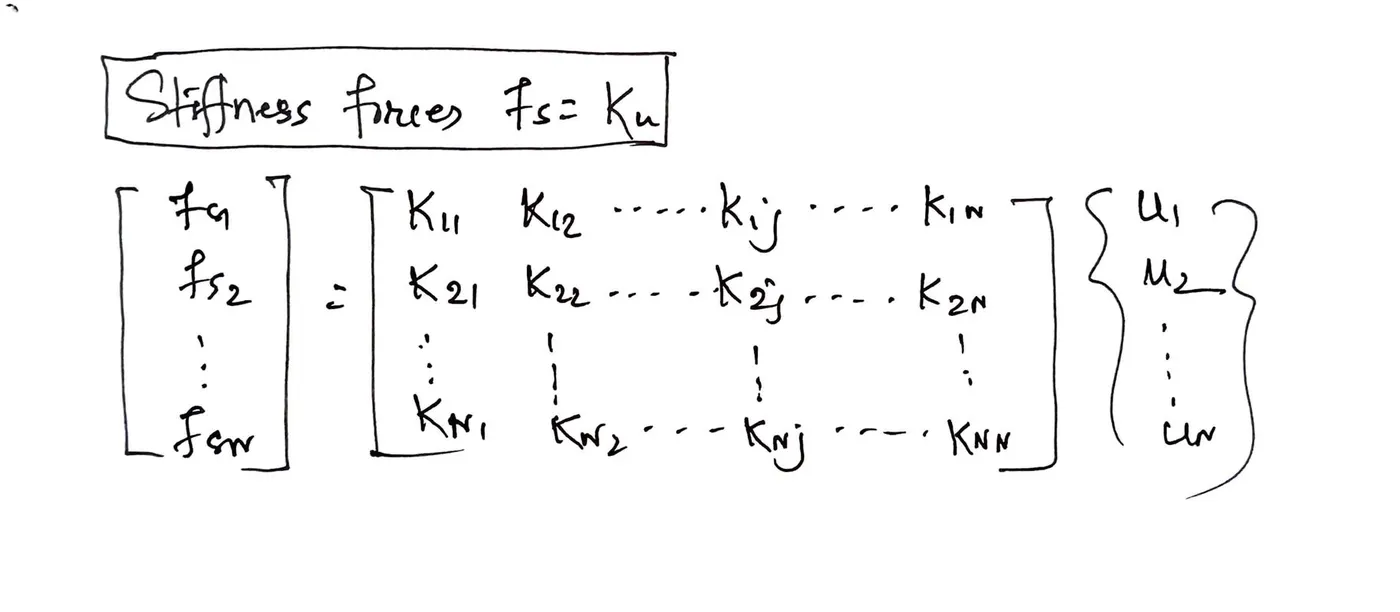
[k]= stiffness matrix of the structure
kij=kji
- Stiffness matrix is symmetric.
Damping component in equation of the motion
- Damping is the processed in the vibrational energy is dissipated by using some mechanical device.
- Its impact is evident from the steady decline in amplitude of a vibrating body.
- Sources of damping in vibrating structures
- Friction at steel connection
- Opening and closing of micro-cracks in concrete
- Friction between the structure and non-structural elements such as partition wall.
- Damping component in equation of motion is impractical to compute the co efficient cij of the damping matrix directly from the dimensions of the structure and the sizes of the structural elements.
- Therefore, damping for MDF systems is generally specified by numerical values for the damping ratio, as for SDF system based on the experimental data for similar structure.
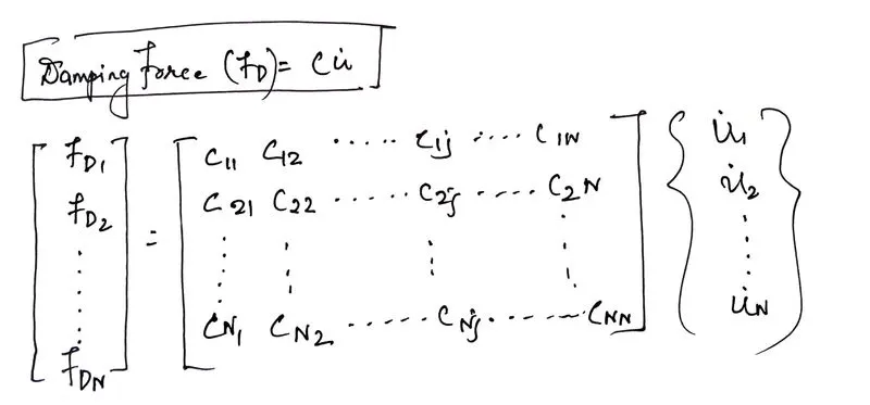
Where c= damping matrix for the structure.
-----------------------------------------------------------------------------------------------------------
4. Provide relationship between Natural period (Tn) & Natural frequency (f) and provide their definitions.
-----------------------------------------------------------------------------------------------------------
ANS-
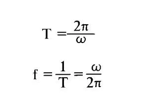
- The natural period of the structure is the time required for one cycle of free vibration. It is related to the natural circular frequency of vibration i.e. the number of rotation in radian per second and the number of cycles per second is called as the natural cyclic frequency of vibration with the unit Hz or cycles/Sec.
The relation between time period and natural circular frequency of vibration and relation between time period and natural cyclic frequency are given below,
- The term natural is used to qualify each of the above quantities to emphasize the fact that these are natural properties of the structural when it is allowed to vibrate freely without any external excitation.
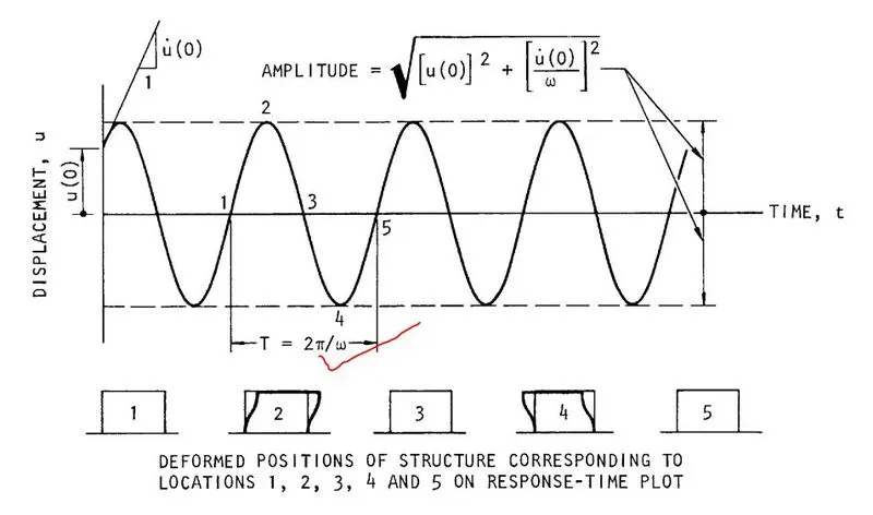
- For the free vibration of an undamped structure, the time period has been shown in the graph between time in x axis and displacement in y axis which is given below,
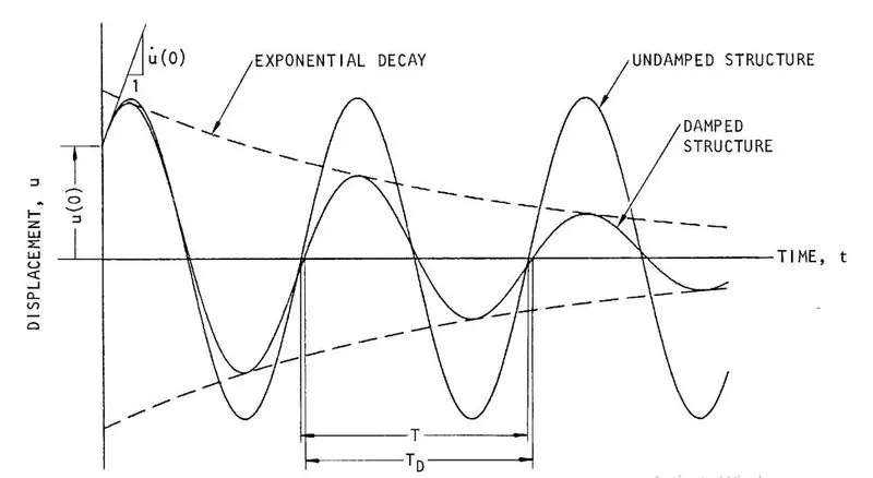
- For the free vibration of damped structure, the time period has been shown in the graph between time in x axis and displacement in y axis which is given below,
-------------------------------------------------------------------------------------------------------------------------
5. Explain in detail about Response spectrum & its Graph.
------------------------------------------------------------------------------------------------------------------------
ANS-
- Response spectrum is the graphical representation of maximum response of structure when time period is shown in x axis and maximum response of displacement, acceleration and velocity in yaxis.
- Response spectrum is a graphical representation of all the peak response of an SDOF structure to a particular earthquake or any dynamic loading, as a function of the natural period and damping ratio of structure.
- For a specific excitation of structure having a particular percentage of critical damping, the maximum response is a function of the natural period of vibration of the system. A plot of the maximum response (e.g., of relative displacement, acceleration, or velocity) against the period of vibration, or against the natural frequency of vibration or the circular frequency of vibration, is called a response spectrum.
- Response spectrum can be represented by displacement response spectrum, velocity response spectrum and acceleration response spectrum which shows the maximum response of dynamic load on the structure with different time period and damping ratio.
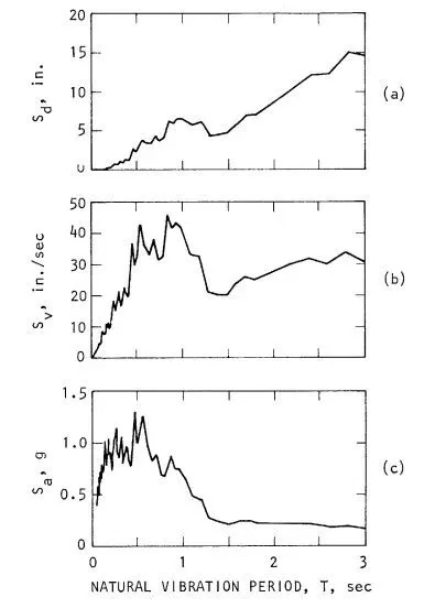
Here Sd, Sv, Sa is represented as displacement response spectrum, velocity response spectrum and acceleration response spectrum respectively.
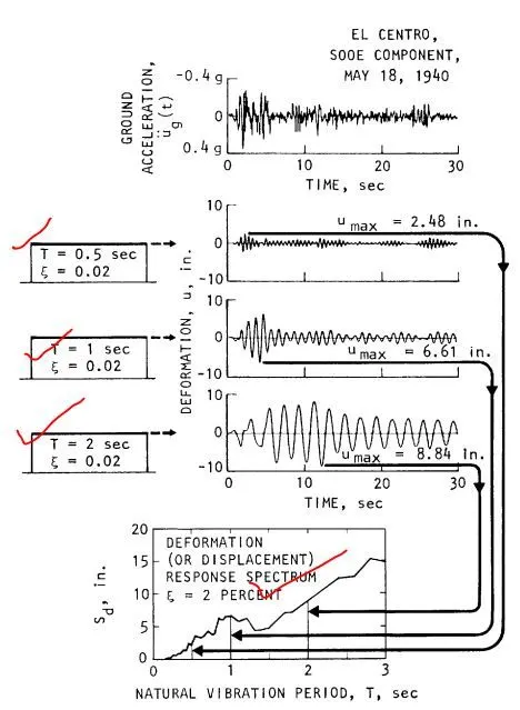
- Example of response spectrum for El centro earthquake (18 may 1940 ) with time period of 0.5 sec, 1sec, 2 sec and damping ratio of 0.02 is show below,
-----------------------------------------------------------------------------------------------------------------------