Drafting of various geometries using Chamfer, Fillet tool in AutoCad
- Aim and introduction
1.1 Aim of the challenge: - Drafting of various geometries using Filler, Fillet tool in AutoCAD.
1.2 Introduction: - Chamfering and fileting in the field of civil engineering is very important in AutoCAD. In this different types of diagram has be done with different of length type units i.e. decimal, engineering, architectural etc.
1.2.1 Chamfer- There are three ways in which chamfer tool can be used that is through ribbon, using toolbar and directly by using command.
- Using ribbon i.e. Home à Modify à fillet drop-down àchamfer
- Using tool bar i.e. Modify à chamfer
- By using command i.e. CHA (CHAMFER)
Basically, we can say, there are so many methods in which we can execute the chamfer operation. Some of them are given below,
- Creating chamfer using the distance option
- Creating chamfer using the select first line option
- Creating chamfer using the polyline option
- Creating chamfer using the angle option
- Creating chamfer using the trim option
- Creating chamfer using the multiple option.
1.2.2 Fillet- There are three ways in which fillet tool can be used that is through ribbon, using toolbar and directly by using command.
- a) Using ribbon i.e. Home à Modify à fillet chamfer drop-down àfillet
- b) Using tool bar i.e. Modify à fillet
- c) By using command i.e. F (FILLET)
Basically, we can say, there are so many methods in which we can execute the fillet operation. Some of them are given below,
- Creating fillet using the radius option
- Creating fillet using the select first object option
- Creating fillet using the polyline option
- Creating fillet using the trim option
- Creating fillet using the multiple option.
1.2.3 Commands used in all the diagrams as given in the challenges no 3
- ‘UN’ for units
- ‘LIMITS’ for specify the limit of the sheet.
- ‘L’ (for line)
- ‘O’ for offset
- ‘MI’ for mirroring the object
- ‘RO” for rotating the object
- “CO” for copy
- “XL” for construction line
- ‘TR’ for trimming the object
- ‘CHA’ for chamfer
- ‘F’ for filleting
- ‘C’ for circle
- ‘REC’ to draw rectangle
- ‘J’ to join
- ‘DIM ‘for dimension
- ‘DDIM’ for dimension style manager
- MT for multi text
1.3 Procedures Drafting of various geometries using Filler, Fillet tool.
1.3.1 For first diagram using decimal unit type
Step 1- As per the given picture, the unit should be taken in Decimal. So to select unit, UN command is used to select the units as decimal and the angle as decimal degrees, as given below.
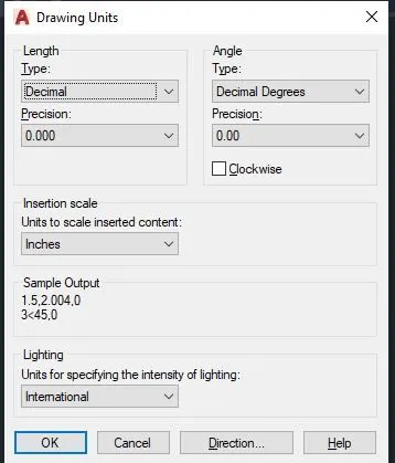
Step 2 limit should be specified the from <0.000,0.000> to <12.000,9.000> by using LIMITS command.
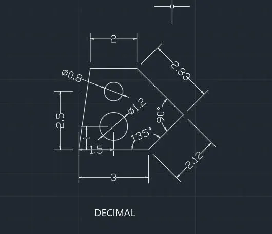
Step 3- Then by using line, circle command with the direct distance entry coordinate system, the given diagram has been drawn.
Screen shots of diagrams using decimal length type.
1.3.2 Diagram no- 2 using architectural unit type
Step 1- As per the given picture, the unit should be taken in ACHITECTURAL. So to select unit, UN command is used to select the units as architectural and the angle as decimal degrees, as given below.
Step 2 limit should be specified the from <0.000,0.000> to <12.000,9.000> by using LIMITS command.
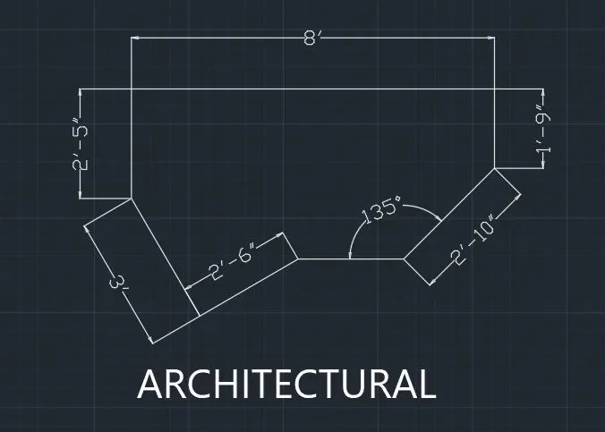
Step 3- Then by using line command with the direct distance entry coordinate system, the given diagram has been drawn.
Step 4- Dimension can be shown by using DIM command and the properties can be modified by using DDIM command.
Screen shots of diagrams using Architectural type.
1.3.3 Diagram no- 3 using engineering unit type
Step 1- As per the given picture, the unit should be taken in engineering. So to select unit, UN command is used to select the units as engineering and the angle as decimal degrees, as given below.
Step 2 limit should be specified the from <0.000,0.000> to <12.000,9.000> by using LIMITS command.
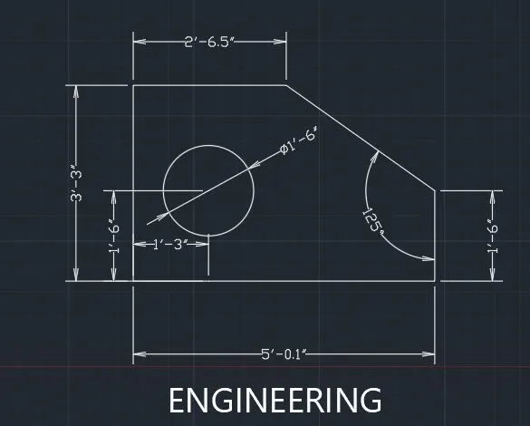
Step 3- Then by using line, circle command with the direct distance entry coordinate system, the given diagram has been drawn.
Step 4- Dimension can be shown by using DIM command and the properties can be modified by using DDIM command.
Screen shots of diagrams using engineering type.
1.3.4 Diagram no- 4 using decimal unit type
Step 1- As per the given picture, the unit should be taken in decimal. So to select unit, UN command is used to select the units as decimal and the angle as decimal degrees, as given below.
Step 2 limit should be specified the from <0.000,0.000> to <12.000,9.000> by using LIMITS command.
Step 3- Then by using line command with the direct distance entry coordinate system, the given diagram has been drawn.
Step 4- Dimension can be shown by using DIM command and the properties can be modified by using DDIM command.
Screen shots of diagrams using decimal type.
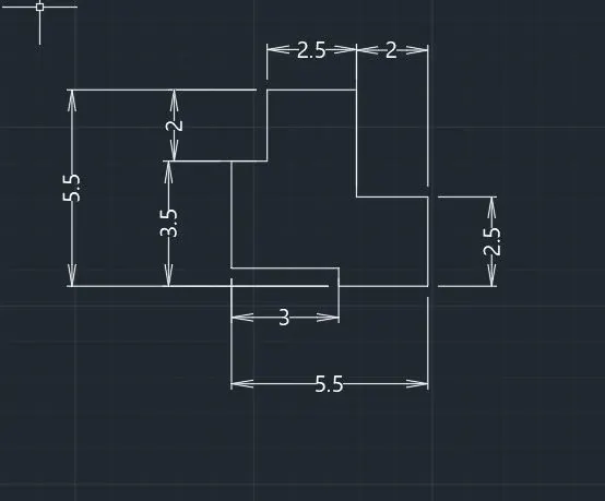
1.3.5 Diagram no- 5 using decimal unit type
Step 1- As per the given picture, the unit should be taken in decimal. So to select unit, UN command is used to select the units as decimal and the angle as decimal degrees, as given below.
Step 2 limit should be specified the from <0.000,0.000> to <12.000,9.000> by using LIMITS command.
Step 3- Then by using line command with the direct distance entry coordinate system, the given diagram has been drawn.
Offset of 6.00, 2.75, 3.00 has been used for line and circle of diameter 3.00, 2.00, 1.00 has been drawn using the C command.
Step 4- Dimension can be shown by using DIM command and the properties can be modified by using DDIM command.
Screen shots of diagrams using decimal type.
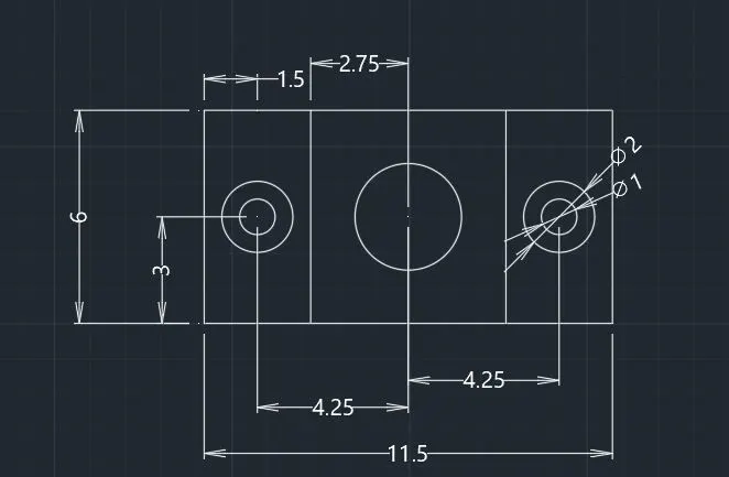
1.3.6 Diagram no- 6 using decimal unit type
Step 1- As per the given picture, the unit should be taken in decimal. So to select unit, UN command is used to select the units as decimal and the angle as decimal degrees, as given below.
Step 2 limit should be specified the from <0.000,0.000> to <12.000,9.000> by using LIMITS command.
Step 3- Then by using line command with the direct distance entry coordinate system, the given diagram has been drawn.
Offset of 0.5, 2.0, 1.5 has been used in the diagram by using the command “O”.
Step 4- Dimension can be shown by using DIM command and the properties can be modified by using DDIM command.
Screen shots of diagrams using decimal type.
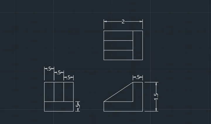
1.3.7 Diagram no- 7 using decimal unit type
Step 1- As per the given picture, the unit should be taken in decimal. So to select unit, UN command is used to select the units as decimal and the angle as decimal degrees, as given below.
Step 2 limit should be specified the from <0.000,0.000> to <12.000,9.000> by using LIMITS command.
Step 3- Then by using line command with the direct distance entry coordinate system, the given diagram has been drawn.
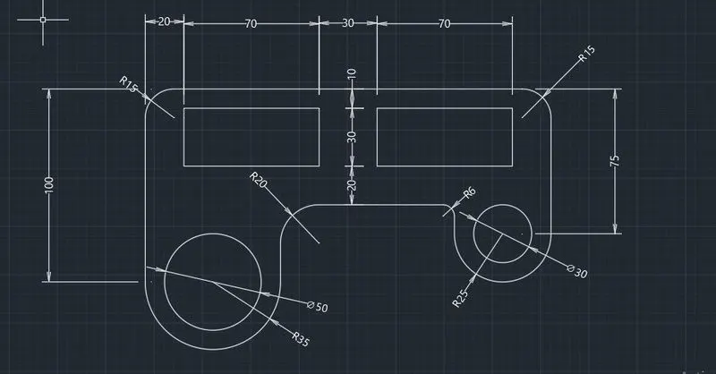
Offset of 70, 30, 10 have been used for line with “O” command.
Circle of diameter 50, 30 have been drawn using the C command.
Fillets of radius 15, 35, 20, 6, 25 have been drawn using the command “F”.
Join tools is used by using the command “J”.
Step 4- Dimension can be shown by using DIM command and the properties can be modified by using DDIM command.
Screen shots of diagrams using decimal type.
1.3.8 Diagram no- 8 using decimal unit type
Step 1- As per the given picture, the unit should be taken in decimal. So to select unit, UN command is used to select the units as decimal and the angle as decimal degrees, as given below.
Step 2 limit should be specified the from <0.000,0.000> to <12.000,9.000> by using LIMITS command.
Step 3- Then by using line command with the direct distance entry coordinate system, the given diagram has been drawn.
Offset of 4.275 have been used for line with “O” command.
Circle of diameter 5, 4, 0.9, 1.8 have been drawn using the C command.
Step 4- Dimension can be shown by using DIM command and the properties can be modified by using DDIM command.
Screen shots of diagrams using decimal type.
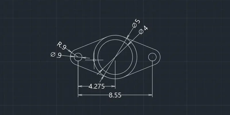
1.3.9 Diagram no- 9 using decimal unit type
Step 1- As per the given picture, the unit should be taken in decimal. So to select unit, UN command is used to select the units as decimal and the angle as decimal degrees, as given below.
Step 2 limit should be specified the from <0.000,0.000> to <12.000,9.000> by using LIMITS command.
Step 3- Then by using line command with the direct distance entry coordinate system, the given diagram has been drawn.
Offset of 32’-6” have been used for line with “O” command.
Circle of radii 8’, 9’ 41’-8” have been drawn using the C command.
Fillet of radius 20’-10” has been drawn using the command “F”.
Step 4- Dimension can be shown by using DIM command and the properties can be modified by using DDIM command.
Screen shots of diagrams using decimal type.
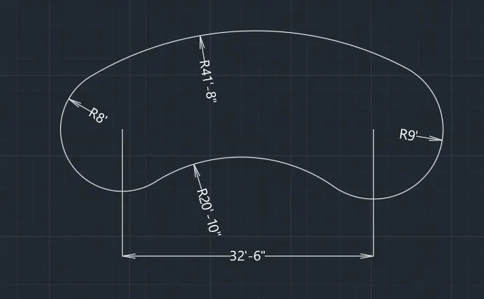
1.3.10 Diagram no- 10 using decimal unit type
Step 1- As per the given picture, the unit should be taken in decimal. So to select unit, UN command is used to select the units as decimal and the angle as decimal degrees, as given below.
Step 2 limit should be specified the from <0.000,0.000> to <12.000,9.000> by using LIMITS command.
Step 3- Then by using line command with the direct distance entry coordinate system, the given diagram has been drawn. Offset of arbitrary value is used.
Step 4- Dimension can be shown by using DIM command and the properties can be modified by using DDIM command.
Screen shots of diagrams using decimal type.
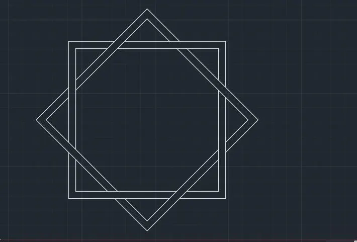
1.3.7 Diagram no- 7 using decimal unit type
Step 1- As per the given picture, the unit should be taken in engineering. So to select unit, UN command is used to select the units as engineering and the angle as decimal degrees, as given below.
Step 2 limit should be specified the from <0.000,0.000> to <12.000,9.000> by using LIMITS command.
Step 3- Then by using line command with the direct distance entry coordinate system, the given diagram has been drawn.
Offset of 20’-4”, 3’ have been used for line with “O” command.
Here, rotation, copy and mirror tools is used by using the RO, CO, MI command.
Step 4- Dimension can be shown by using DIM command and the properties can be modified by using DDIM command.
Screen shots of diagrams using engineering type.
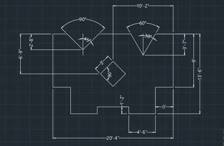
Results-
All the results of the respective diagrams have been shown as above and the .dwg file is uploaded.