Identification of Cracks
1-a- Solution
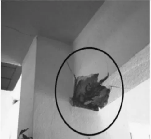
Observation
- Below the neutral axis of Concrete in the beam i.e. at the joint of column and wall is crushed and the reinforcement is exposed to outside.
- Top of the beam looks uncracked, undamaged and safe because the flange advantage of slab which supports and restrain the top of the beam.
- Internal concrete in the beam has come out of the structure which may be the sign of rupture.
- The micro crack and some major crack has been seen from bottom to top means the reinforcement yielding occurs in support bottom only.
Conclusion
- Due to stress reversal during earthquake, at the junction of the beam in the bottom part of the building under goes the tensile stress which causes the flexural failure.
- Due to stress reversal. It experiences compression on top of beam and tension on bottom, as the compression on top part of the beam is managed by slab advantage and bottom part was not satisfied by the provided reinforcement.
- It looks like the yield in reinforcement has already been occurred, so it cannot be repaired.
---------------------------------------------------------------------------------------------------------------------------
1-b- Solution
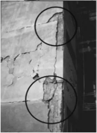
Observation
- Photograph look like it is beam column joint at the edge part. Big and wide cracks can be seen on the edge of beam-column and wide crack on the middle of the beam also.
- Beam looks detached from the column at joints and cracks seem to have developed through the structure.
- Concrete in the middle of beam is not severely crushed as nothing has been seen that bulged out of structure.
Conclusion
- This is beam pull out failure because of insufficient development length of the beam reinforcement in the beam column joint and also due to inadequate anchorage of reinforcement.
- At the time of earthquake, due to horizontal movement of the structure, the horizontal member like beam starts detaching from the column member.
- By providing the sufficient anchorage length in the beam column joint, but for existing concrete, it very difficult to provide the development length. So it is not repairable.
--------------------------------------------------------------------------------------------------------------------------
1-c- Solution
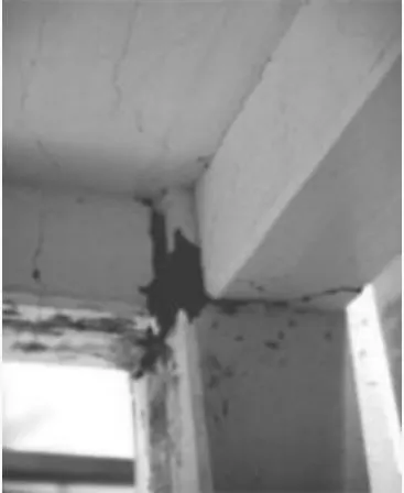
Observation
- In the given photograph, it is clearly visible that two beam is connected to one column in which cracks has been developed at the joint at the junction of beam and column.
- Cracks in beam is developed through the entire beam width and also some cracks also be developed on the slab along with the beam cracks.
Conclusion
- This is a plastic hinged failure due to stress reversal plastic moment is achieved near the joint.
- Due to the lateral loading and stress reversal at the joint led to this type of damage and it is clearly seen that damage is occurred at the joint only.
- Due to heavy tensile stress developed on the top of beam, the slab participated to its best to resist this tensile stress and unable to control the damage and some cracks has also seen on the slab surface.
- As the damage does not look critical crack, so the joint can strengthened.
----------------------------------------------------------------------------------------------------------------------------
2-a- Solution
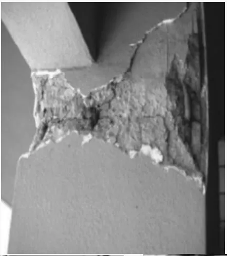
Observation
- Spalling of concrete has been seen in the column and little bit of reinforcement is exposed to outside, beam is safe.
- Concrete in column is damaged at the top of column and it is all around on the column only.
- The location of column looks at edge of the building and it is slightly buckle just below the joint.
- No walls are built along the column means it might be a ground floor structure for movement of parking car.
Conclusion
- This is a plastic hinged failure as it clearly seen that plastic hinge is formed just below the joint in the column and soft storey failure.
- Due to free space under the beam at the ground floor, the plastic hinged form at top of ground storey column during lateral movement due mass irregularity.
- Based on the development of the crushing or spalling of concrete, it can either be repairable or non-repairable.
---------------------------------------------------------------------------------------------------------------------------
2-b- Solution
Observation
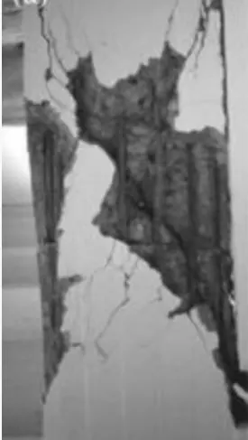
- In this photo, it is clearly seen that spalling of concrete and the damage is diagonal.
- Longitudinal reinforcements are intact and in place.
- One of the shear reinforcement is slightly displaced and spacing between two shear reinforcement looks wider.
Conclusion
- It is a pure shear failure.
- It is impossible to provide the shear reinforcement in the existing concrete so it is not repairable.
-------------------------------------------------------------------------------------------------------------------------
2-c- Solution
Observation
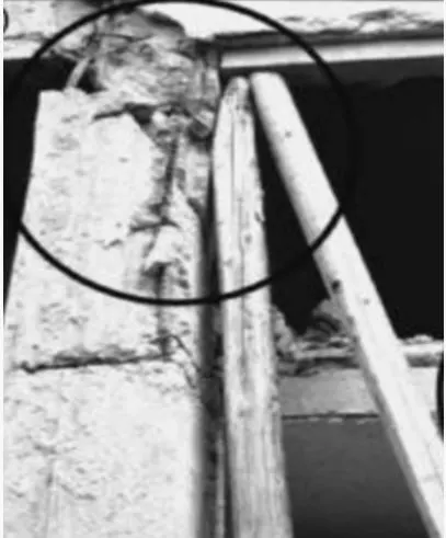
- Column is complete failed and there is no bonding between upper column and bottom columns.
- Damage is observed at top of the column.
- There are two slabs connected to the column, probably one at the mid height of the column.
- The wooden piles is used to support after column failed, providing temporary prop to avoid collapse of entire structure.
Conclusion
- It is a short column failure.
- A heavy shear force is generated due to an additional slab or beam connected to a column in mid height leads to this type of effect.
- This leads to failure if the connection is unintentional and not accounted in design,
- This type of failure is not at all repairable.
--------------------------------------------------------------------------------------------------------------------------------