3D Creation of Ceiling, Roof, Architectural plan, Structural plan, Sectional view, Elevation view and Camera specific view for a house plan using REVIT
QUE-1) Based on the project saved from Week 3, proceed from the First Floor Level. Model a Ceiling from the architecture tab above the walls at the first-floor level.
------------------------------------------------------------------------------------------------------------------------------------------
1.1 AIM- To model a Ceiling from the architecture tab above the walls at the first-floor level based on the project saved from week 3.
1.2 PROCEDURE- All the details procedure in modeling of the ceiling at the first floor level is discussed below,
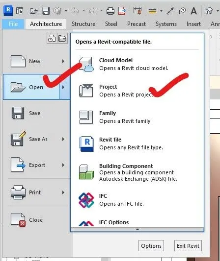
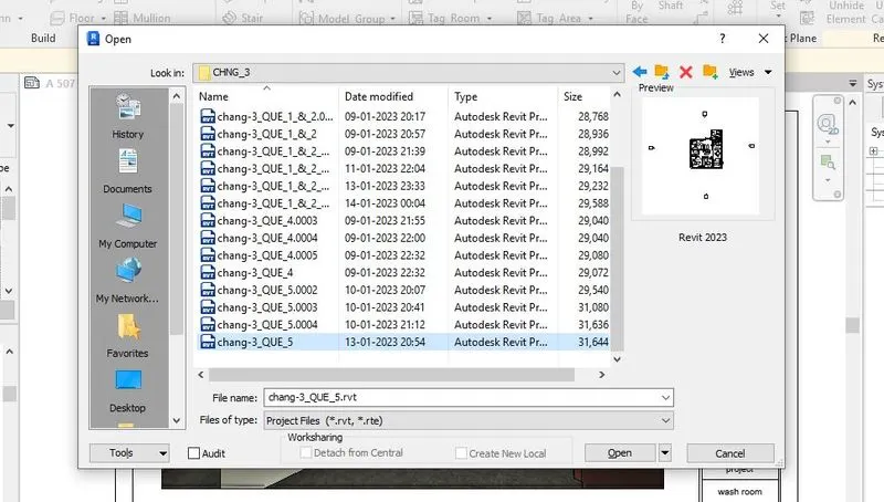
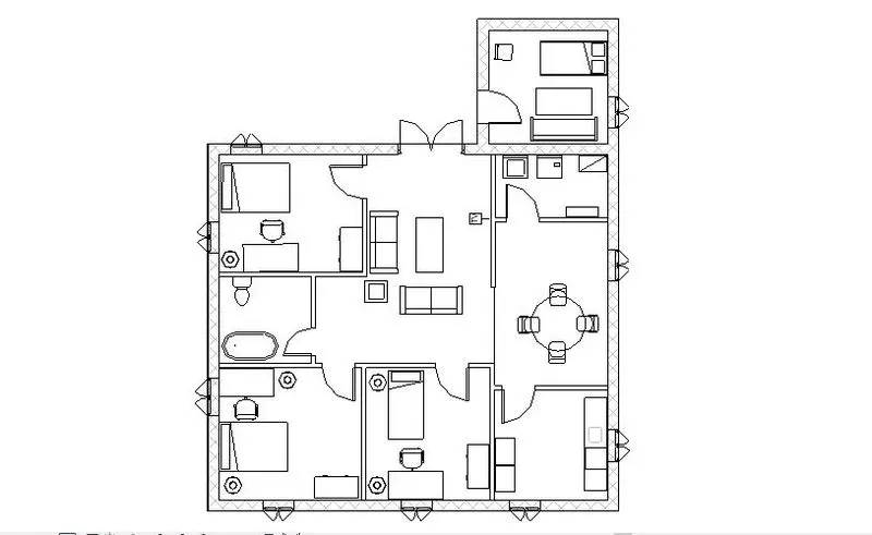
Step 1- Opening of the floor plan with furniture of the chng_3 by using the open tab from the file.
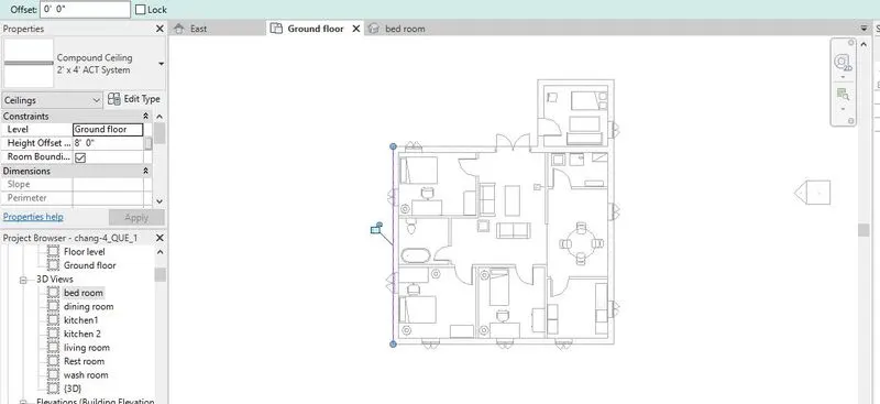
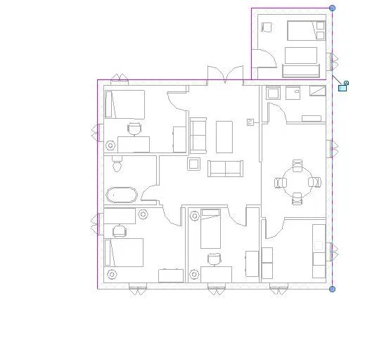
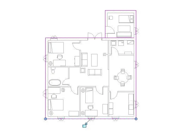
Step-2- After opening the rvt file from chng_3, the select the ceiling option from the architecture where the sketch ceiling option is to be selected for drafting of the ceiling in the required place.
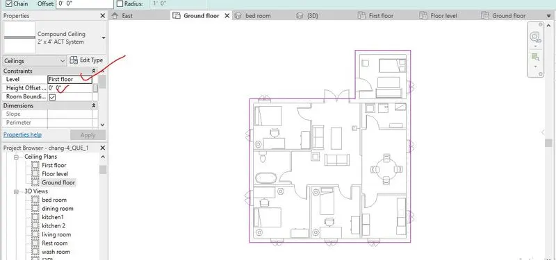
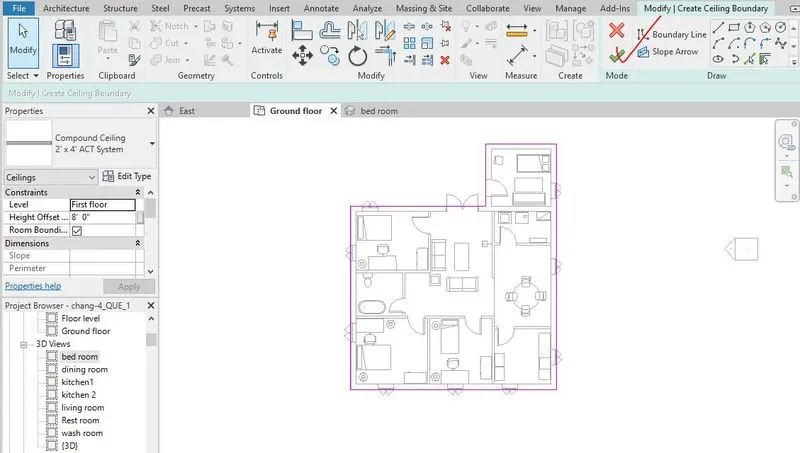
Step-3- After opening of the modify/ created ceiling boundary, by selecting the pick line or line option, the required ceiling where is to be drawn as per the project requirements and required level with appropriate height offset.
Step-4- In case of multi floor building, the ceiling can be pasted to the other floor also.
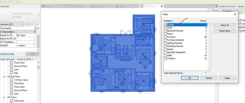
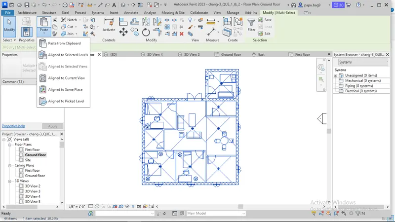
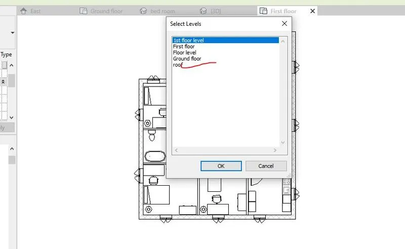
For the pasting of the ceiling in the other floor, first of all the ceiling of the ground floor is selected, then the selected object is copied by selecting the copy option from the modified/ multi select tab and then the copied item is pasted to the required floor by choosing the aligned to the selected level and then pop up will appear where the selected level is selected.
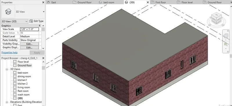
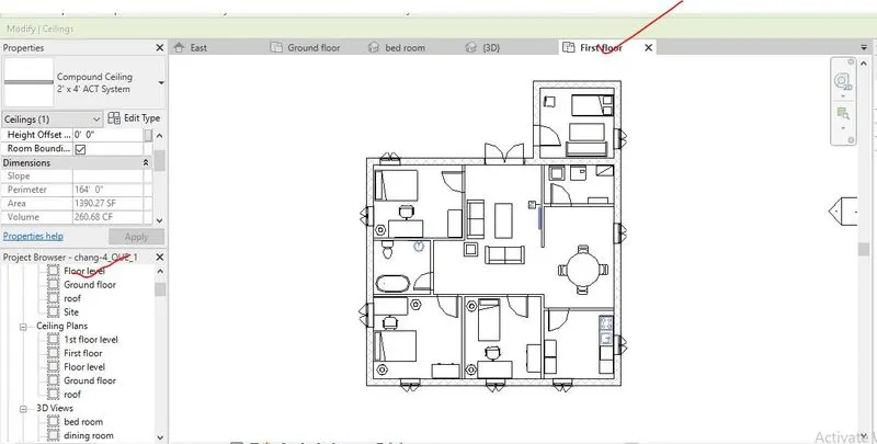
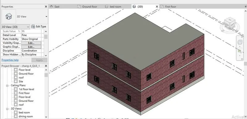
Screenshot of modelling of a Ceiling from the architecture tab above the walls at the first-floor is given below,




1.3 RESULTS-
The results of modelling of a Ceiling from the architecture tab above the walls at the first-floor i.e. the .rvt file is uploaded named as 'chang-4_QUE_1'.
-----------------------------------------------------------------------------------------------------------------------------------------
QUE-2) Model a roof above the ceiling by selecting the footprints of the ceiling. Using the adjustment toolbars appearing on-screen adjust the roof slope to 10 degrees.
-------------------------------------------------------------------------------------------------------------------------------------
2.1 AIM- To model a roof above the ceiling by selecting the footprints of the ceiling by using the adjustment toolbars appearing on-screen adjust the roof slope to 10 degrees.
2.2 PROCEDURE- All the details procedure in modeling of the roof above the ceiling by selecting the footprints of the ceiling by using the adjustment toolbars appearing on-screen adjust the roof slope to 10 degrees is discussed below,
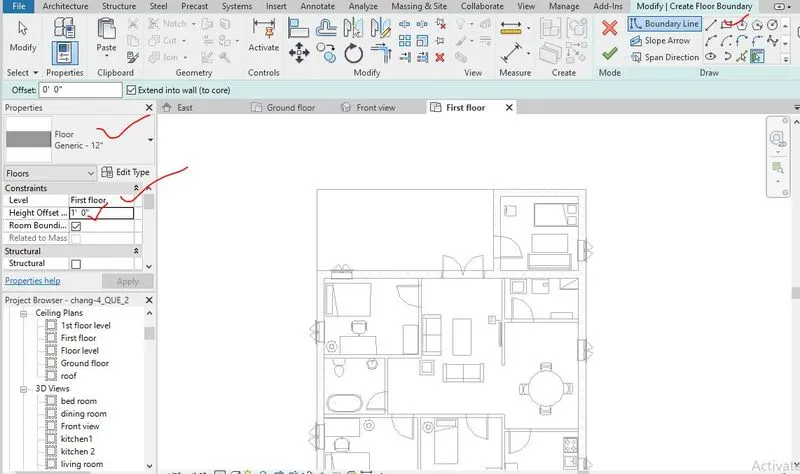
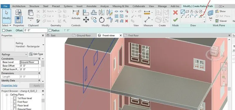
Step 1- To create roof, first the roof option is selected from the architecture tab where the different type of floors like roof by footprint, roof by extrusion, roof by face, soffit roof, fascia roof, gutter roof can be selected, as per the project requirement, the roof by footprint is to selected.
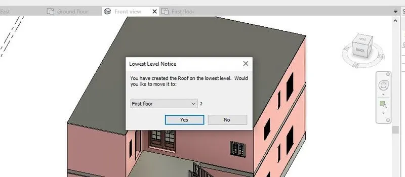
Step-2- As soon as the roof by footprint is selected, a pop up box will where the lowest level notice is selected as first level.
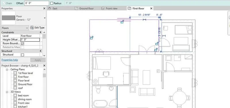
a modify / create floor boundary tab will open where the roof can be drawn by selecting the any option like line, pick line, rectangular etc.
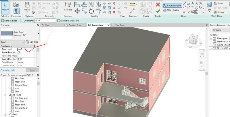
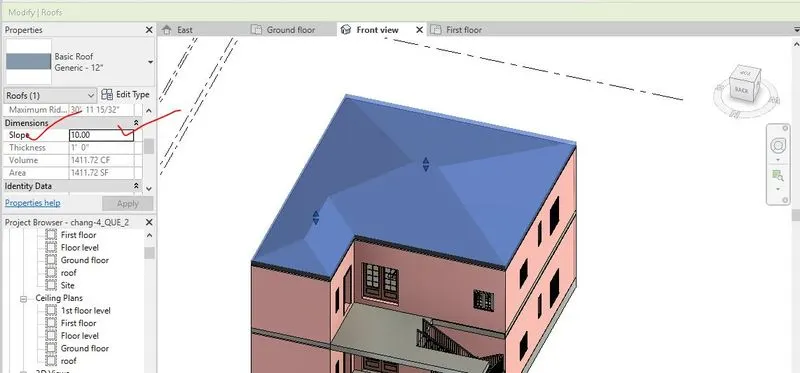
Step-3- From the properties browser, the different type of roof, base level height, slope etc. is selected, in this project thickness floor of 12”’ and base level height of 0’ as the roof level selected which is created earlier is selected and type of floor i.e. Basic roof generic 12”.
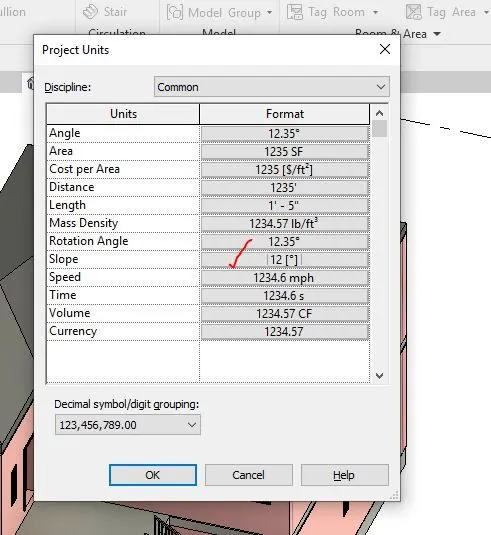
Step-4- from the properties browser, the slope of the roof is changed to the 10 degrees.
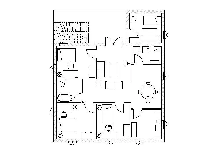
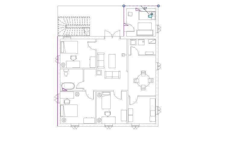
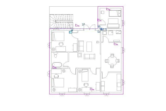
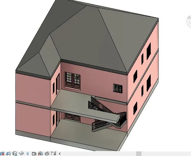
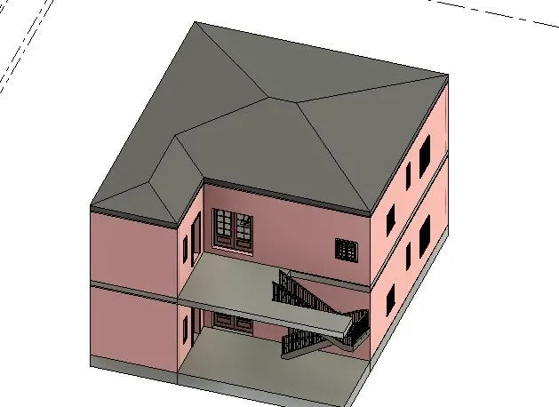
Screenshot of modelling of roof above the ceiling by selecting the footprints of the ceiling by using the adjustment toolbars appearing on-screen adjust the roof slope to 10 degrees is given below,



2.3 RESULTS-
The results of modeling of the roof above the ceiling by selecting the footprints of the ceiling by using the adjustment toolbars appearing on-screen adjust the roof slope to 10 degrees i.e. the .rvt file is uploaded named as 'chang-4_QUE_2'.
-----------------------------------------------------------------------------------------------------------------------------------------
QUE-3) Using the file saved from weeks 2 to 4, create plan views for ground floor level and first-floor level including all the walls, floors, and components. Separate them to architecture and structural plans.
a. Architecture plan must have walls, floors, and all the components placed within the building
b. Structure plan must have details of only walls, floors, and columns
-------------------------------------------------------------------------------------------------------------------------------------
3.1 AIM- To create plan views for ground floor level and first-floor level including all the walls, floors, and components. Separate them to architecture and structural plans.
3.2 PROCEDURE- All the details procedure in creating plan views for ground floor level and first-floor level including all the walls, floors, and components and Separating them to architecture and structural plans is discussed below,
Step-1- First the floor plan of the challenge 2 is opened by using file option from where the file is saved.
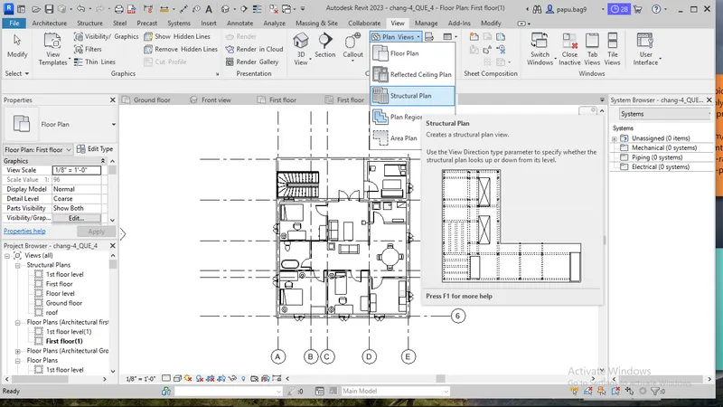
Step-2- To view the architectural plan and structural plan, the view option is selected.
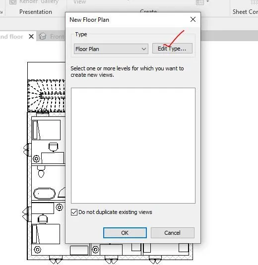
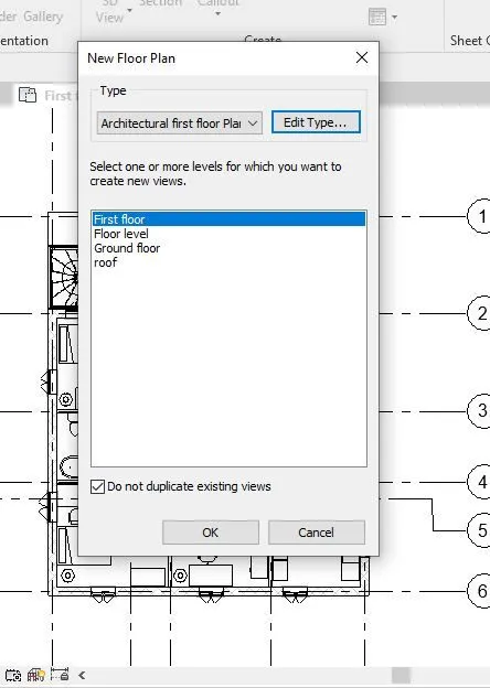
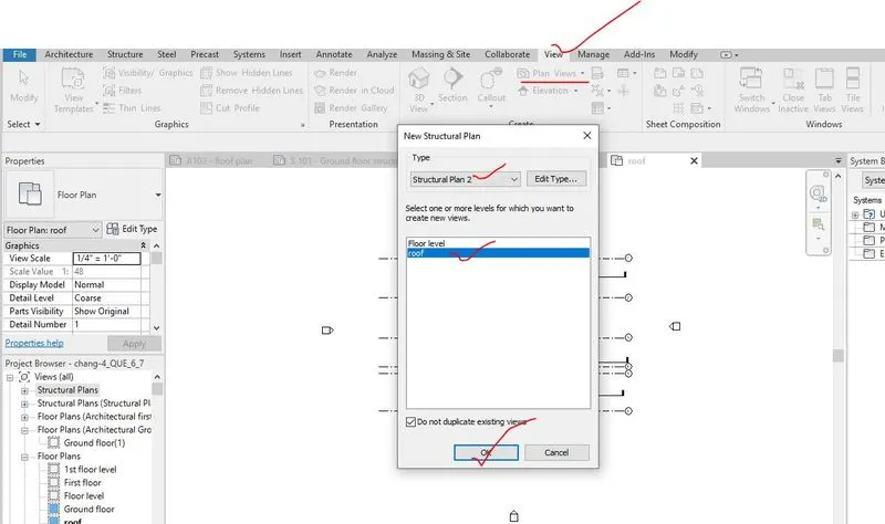
Step-3- after selecting the view option, then plan views is selected where a pop-up will open where the floor plan is selected for architectural plan and structural plan is chose for structural plan.
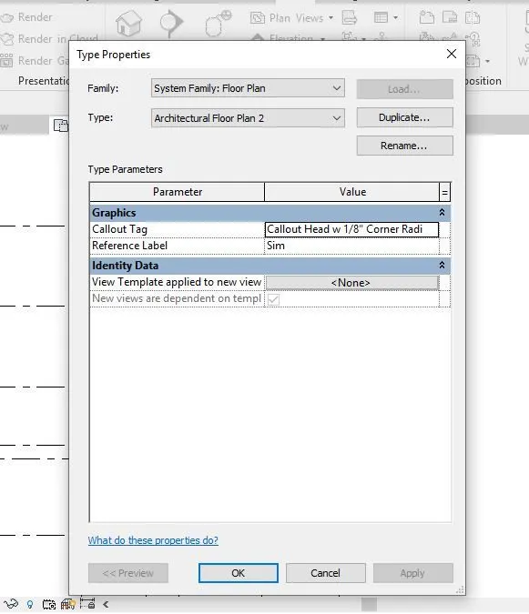
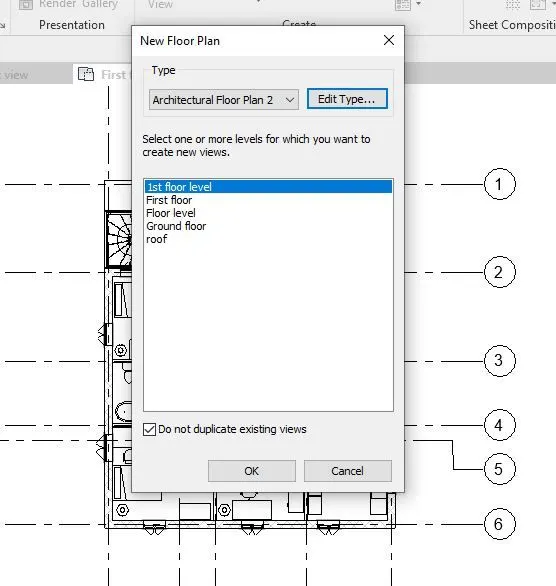
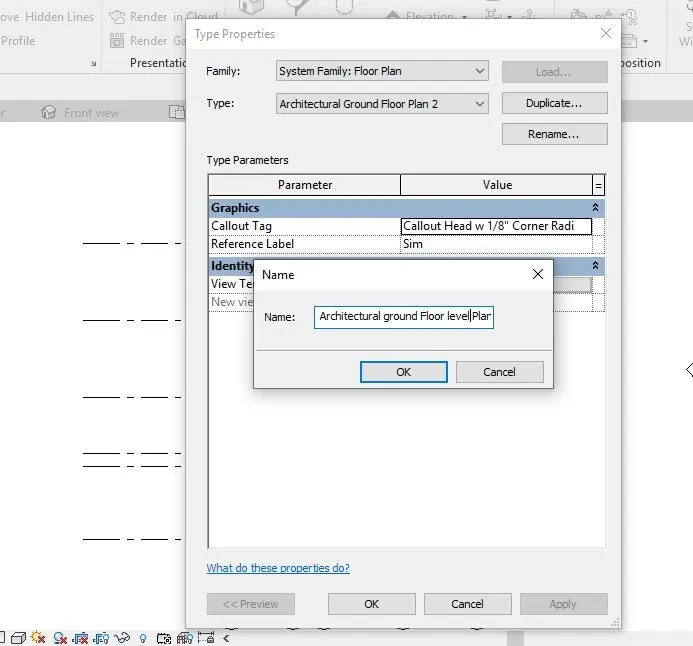
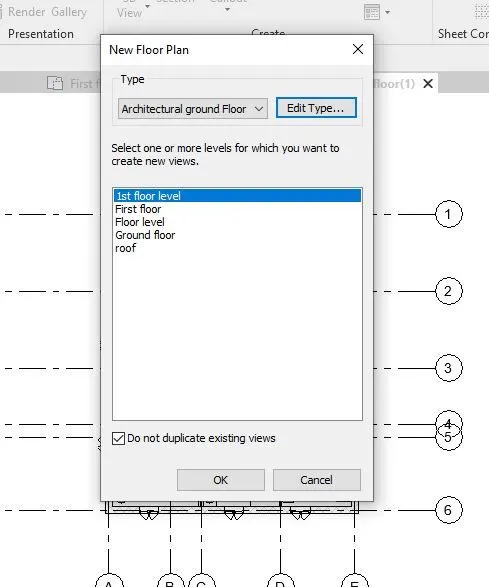
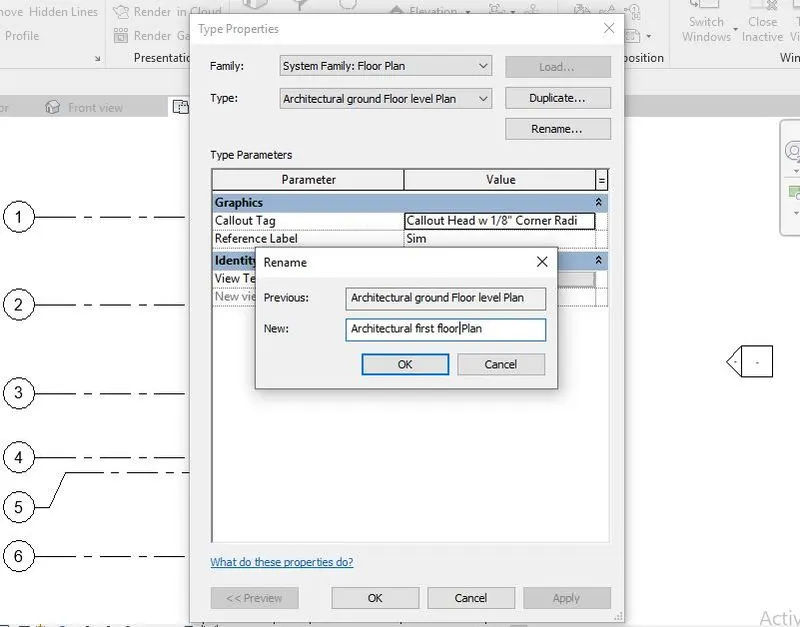
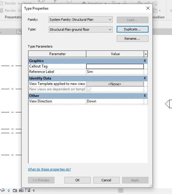
Step-4- after selection of the floor plan, pop up box will open where the required floor can be selected as per required by clicking of the edit type and the name of the floor plan also changed.
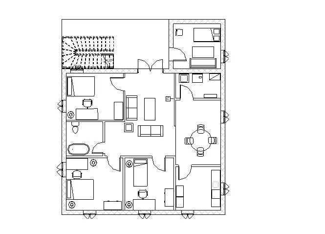
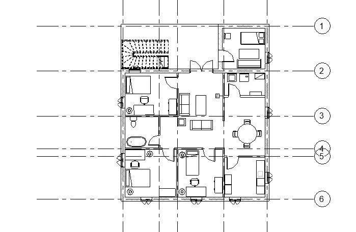
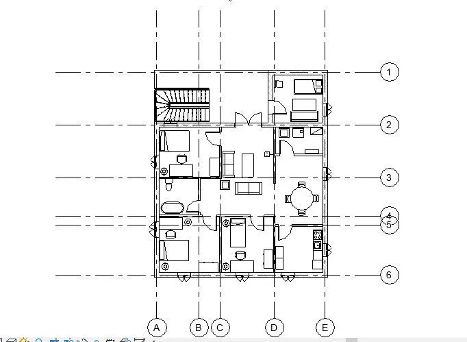
Step-5- After editing the name of the architectural plan, by selecting the required level, the architectural plan is opened.
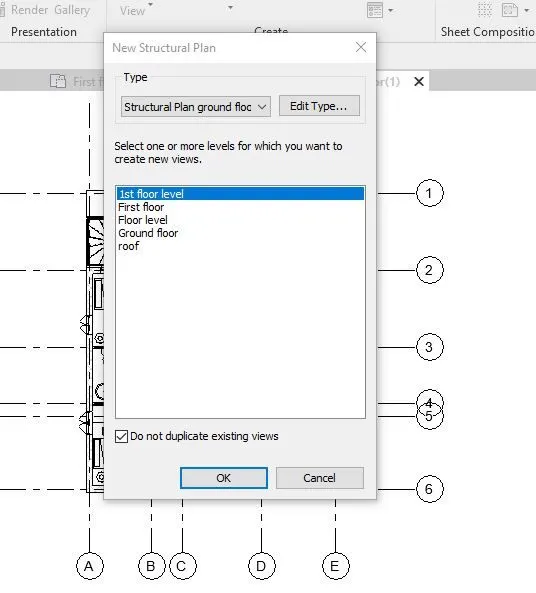
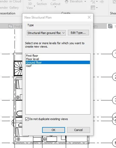
Step-6- The structural plan is also obtained the same way the architectural plan has been obtained.
Screenshot of creating plan views for ground floor level and first-floor level including all the walls, floors, and components and Separating them to architecture and structural plans is given below,

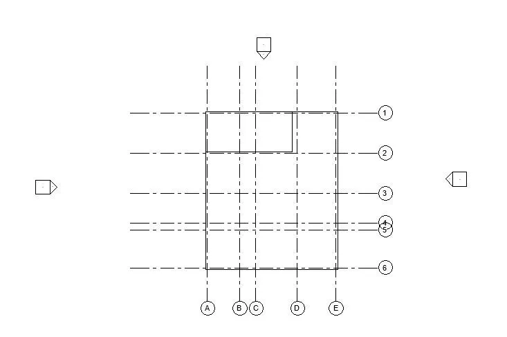
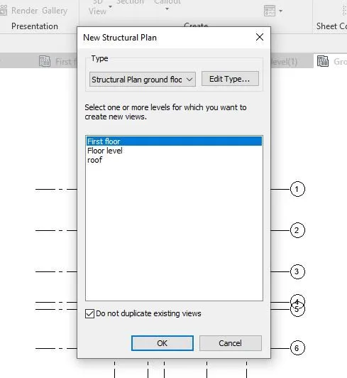
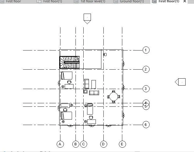
3.3 RESULTS-
The results of creating plan views for ground floor level and first-floor level including all the walls, floors, and components and Separating them to architecture and structural plans i.e. the .rvt file is uploaded named as 'chang-4_QUE_3'.
-----------------------------------------------------------------------------------------------------------------------------------------
QUE-4) Using annotate toolbar add dimensions to all the walls and floors with reference to the longitudinal and transverse grids created in the project file.
a. The architecture plan dimensions include details on where the components are placed within the buildings with relation to grids. Overall dimensions are sufficient for architecture plans.
b. The Structure plan dimensions must include details on the position of all the walls and interior walls with reference to grids. Locate all the framing components of the building with reference to a fixed point using Structural plans.
-------------------------------------------------------------------------------------------------------------------------------------
4.1 AIM- To add dimensions to all the walls and floors with reference to the longitudinal and transverse grids created in the project file.
4.2 PROCEDURE- All the details procedure to add dimensions to all the walls and floors with reference to the longitudinal and transverse grids created in the project file is discussed below,
Step-1- First the floor plan of the challenge 2 is opened by using file option from where the file is saved.
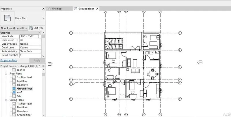
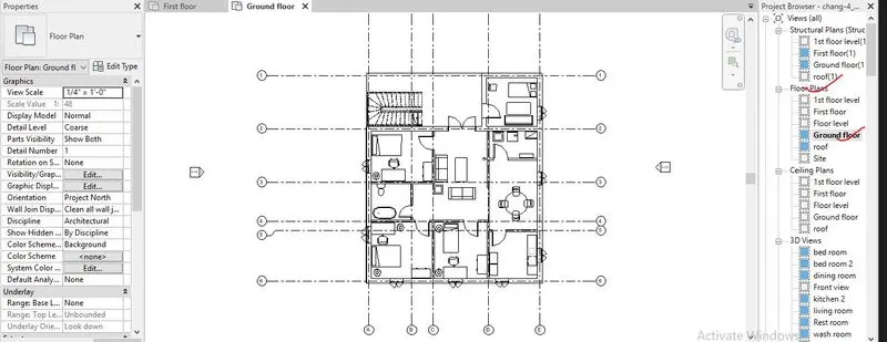
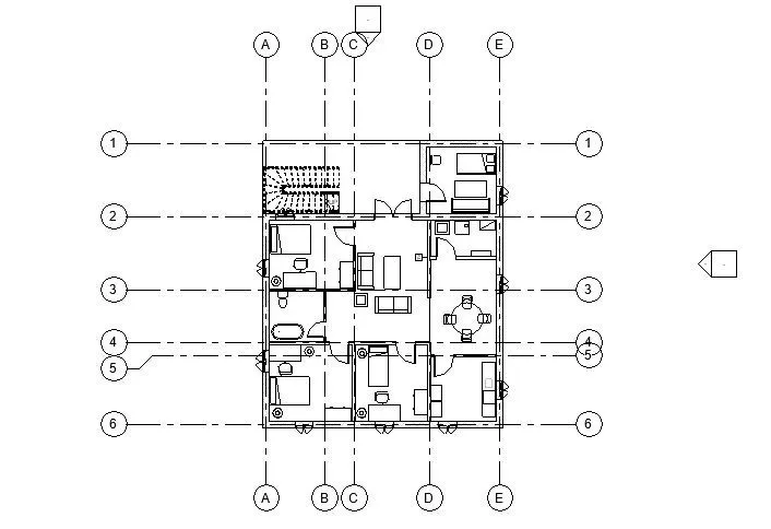
Step-2- after creation of the architectural plan and structural plan by using view option. To annotate the all the component of the architectural plan and structural plan in the building, the annotate is selected.
Step-3- From the properties browser, the floor plan i.e. the architectural plan of ground floor is selected.
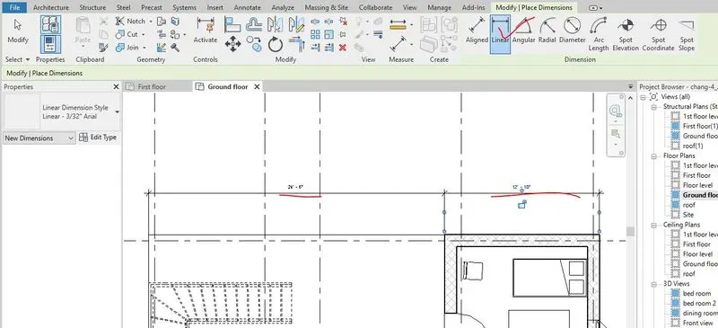
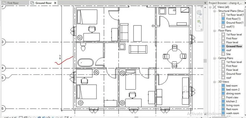
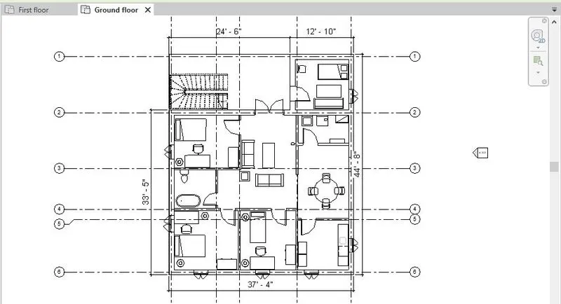
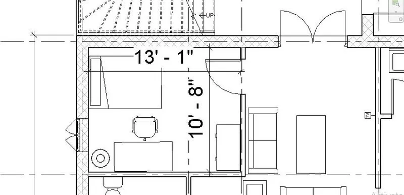
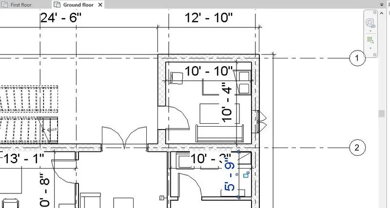
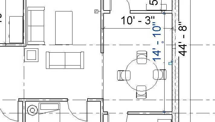
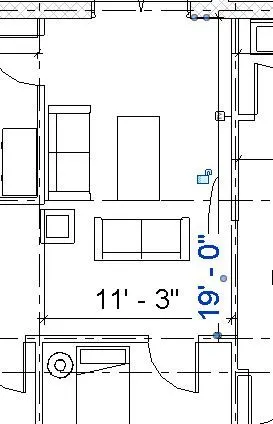
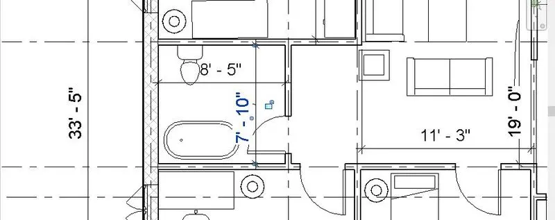
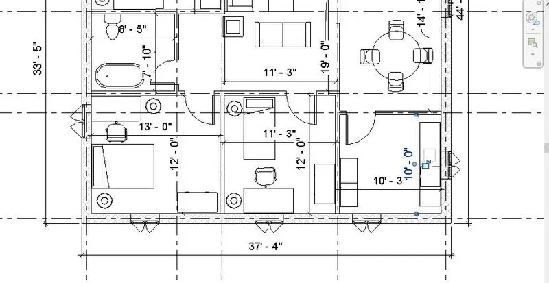
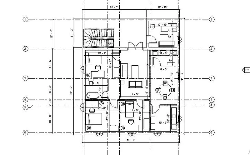
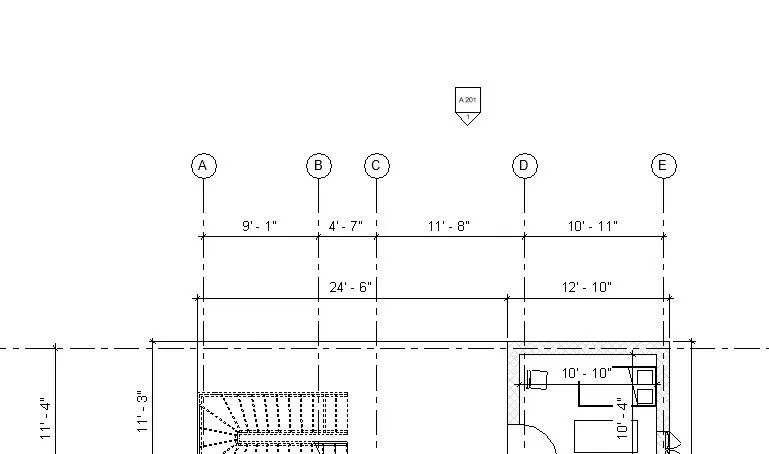
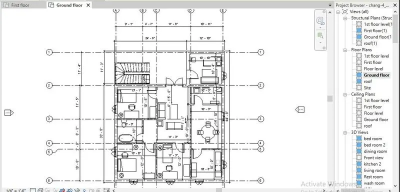
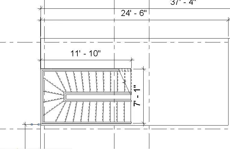
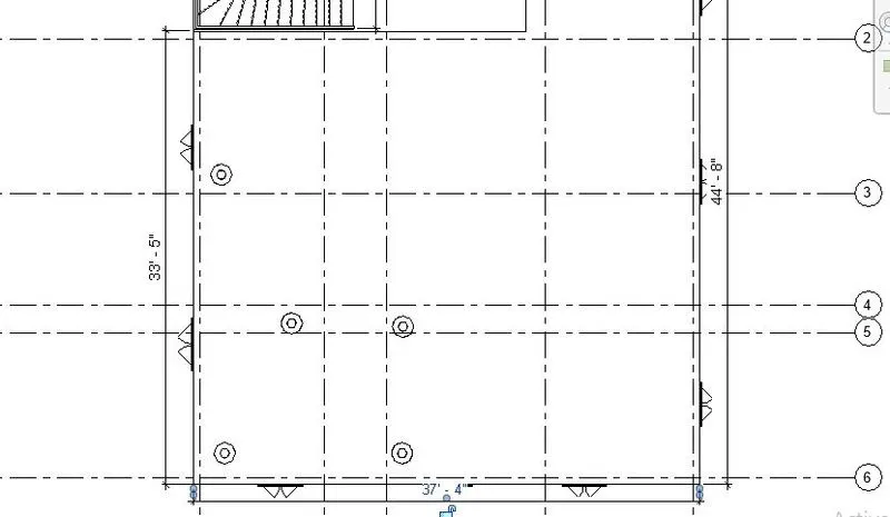
Step-4- after selection of the floor plan, then the annotate tab is selected, where by using the linear and aligned dimension, all the dimension of wall to wall and room is annotated.
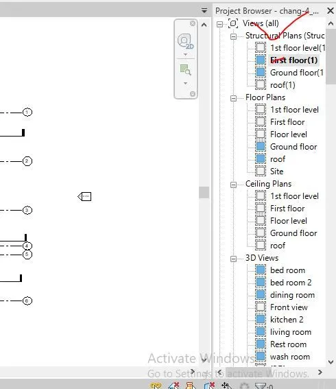
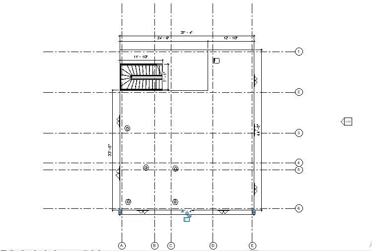
Step-5- To annotate the structural plan, first of all the structural plan is selected here in this project the structural plan of first floor plan is selected from the properties browser.
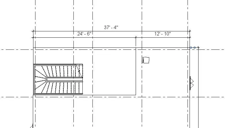
Step-6- after selection of the structural plan, then the annotate tab is selected, where by using the linear and aligned dimension, all the dimension of wall to wall and structural component like stair is annotated.
Screenshot of adding dimensions to all the walls and floors with reference to the longitudinal and transverse grids created in the project file is given below,
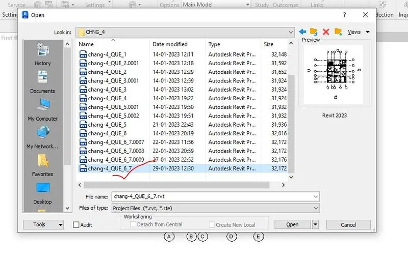


4.3 RESULTS-
The results of adding dimensions to all the walls and floors with reference to the longitudinal and transverse grids created in the project file i.e. the .rvt file is uploaded named as 'chang-4_QUE_6_7'.
-----------------------------------------------------------------------------------------------------------------------------------------
QUE-5) Create a sheet template from the view tab and adjust the parameters on the sheet to add appropriate views.
-------------------------------------------------------------------------------------------------------------------------------------
5.1 AIM-To create a sheet template from the view tab and adjust the parameters on the sheet to add appropriate views.
5.2 PROCEDURE- All the details procedure in creating a sheet template from the view tab and adjust the parameters on the sheet to add appropriate views is discussed below,
Step-1- First the floor plan of the challenge 2 is opened by using file option from where the file is saved.
Step-2- By clicking on the view tab, the sheet tools are selected to add the appropriate view of the projects.
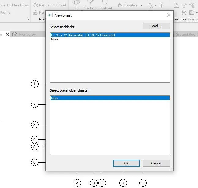
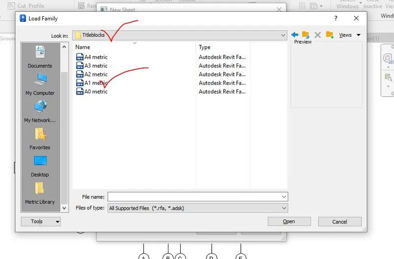
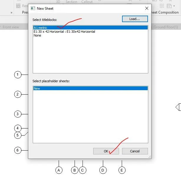
Step-3- After selecting the sheet tool, a pop up box will open where the title-blocks can be loaded as per the required size. Here the A1 matric has been chose from the title blocks.
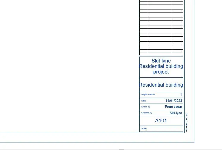
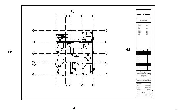
Step-4- After selection of the A1 matric sheet, an A1 size sheet has been open where the project information is updated.
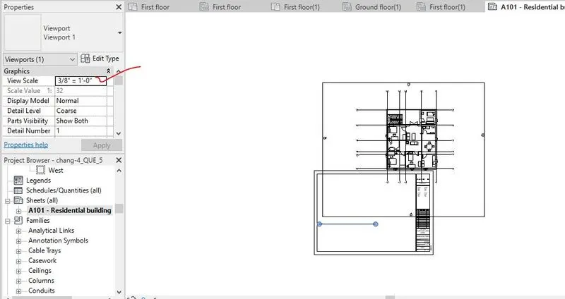
Step-5- From the project browser, the floor plan or any other project documents is added to the sheet and by changing the scale, an appropriate size is adjusted.
Screenshot of creating a sheet template from the view tab and adjust the parameters on the sheet to add appropriate views is given below,

5.3 RESULTS-
The results of creating a sheet template from the view tab and adjust the parameters on the sheet to add appropriate views i.e. the .rvt file is uploaded named as 'chang-4_QUE_5'.
-----------------------------------------------------------------------------------------------------------------------------------------
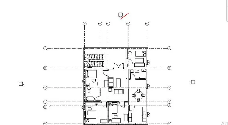
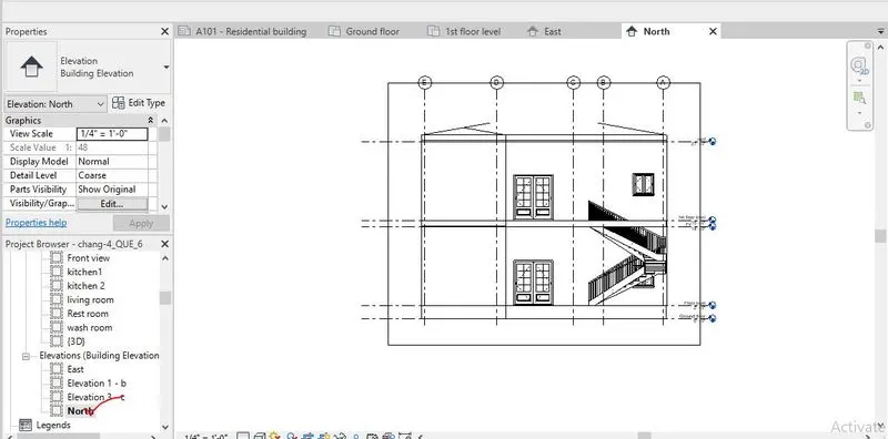
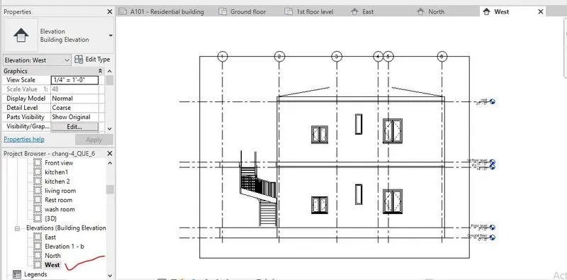
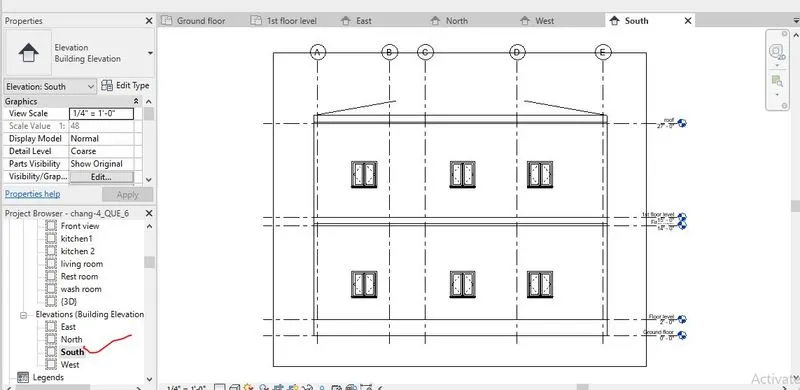
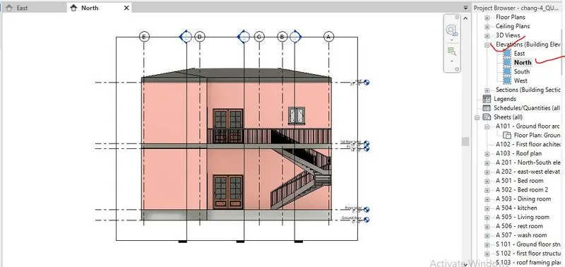
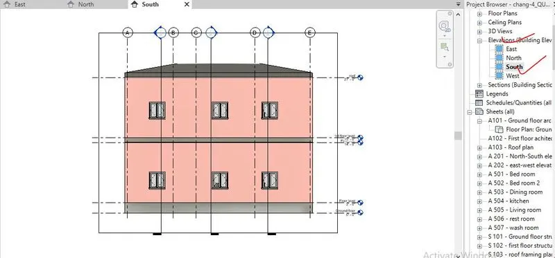
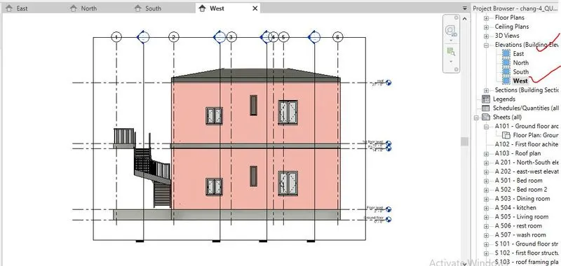
QUE-6) Using the elevation tab create the elevation views, looking at your building from East, North, South, and West.
-------------------------------------------------------------------------------------------------------------------------------------
6.1 AIM- To create the elevation views, looking at your building from East, North, South, and West by using the elevation tab.
6.2 PROCEDURE- All the details procedure in creating the elevation views, looking at your building from East, North, South, and West by using the elevation tab is discussed below,
Step-1- First the floor plan of the challenge 2 is opened by using file option from where the file is saved.
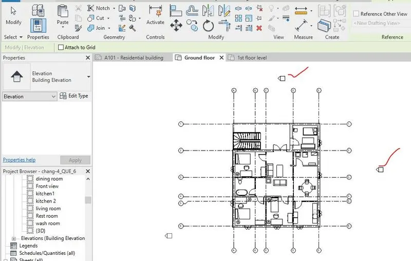
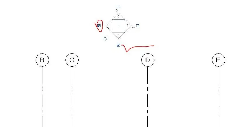
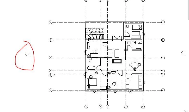
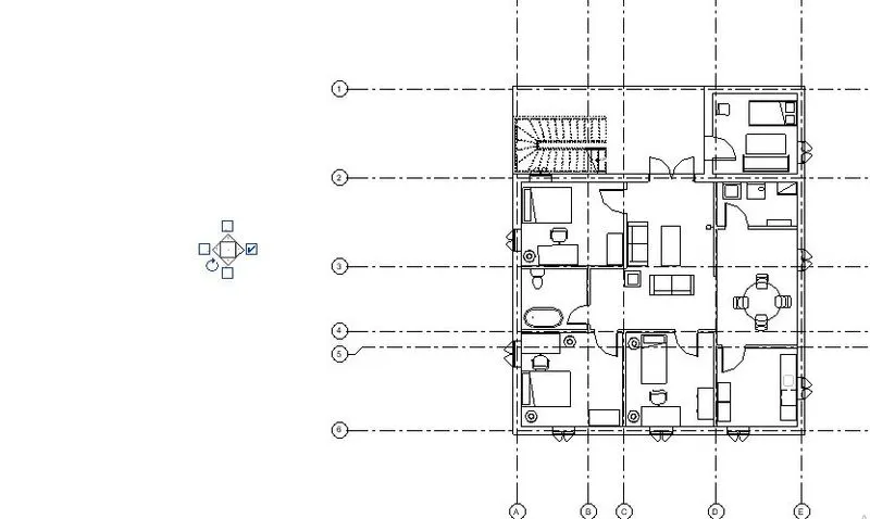
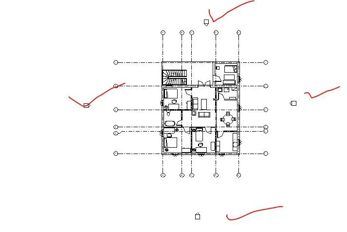
Step-2- By clicking on the elevation tool from the view tab, an elevation box will be open with the direction where the requited direction can be selected as per required view.
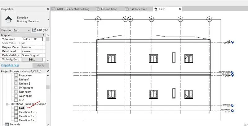
Step-3- the elevation view is named by selecting the rename option which is selected by right clicking on the correspondence view from project browser like east, west, north, south etc.
Step-4- The elevation view is viewed by clicking on the respective selection from the project browser.
Screenshot of creating the elevation views, looking at your building from East, North, South, and West by using the elevation tab is given below,

6.3 RESULTS-
The results of creating the elevation views, looking at your building from East, North, South, and West by using the elevation tab i.e. the .rvt file is uploaded named as 'chang-4_QUE_6'.
-----------------------------------------------------------------------------------------------------------------------------------------
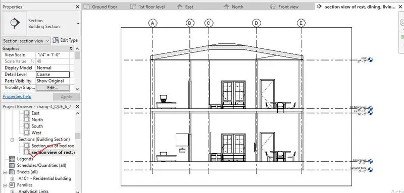
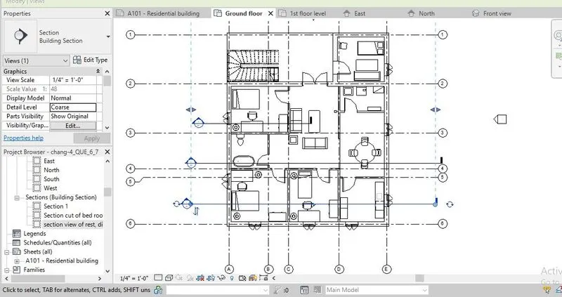
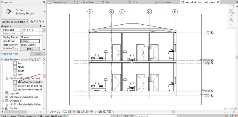
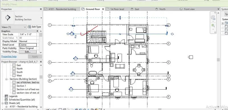
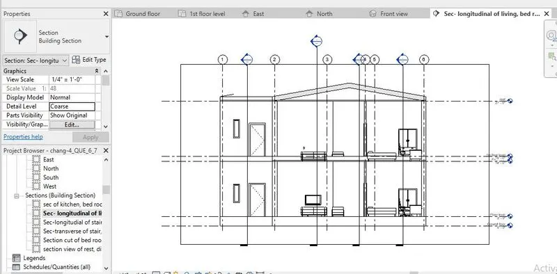
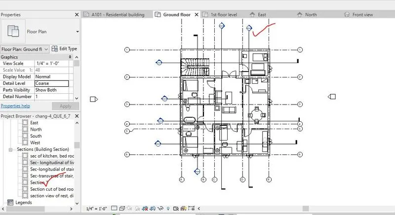
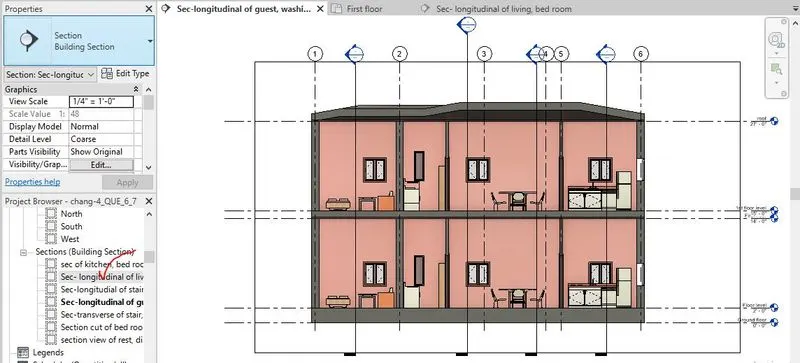
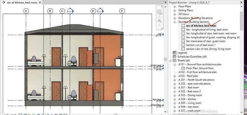
QUE-7) Produce section cut through each room either cutting across longitudinally or in a transverse direction.
-------------------------------------------------------------------------------------------------------------------------------------
7.1 AIM- To produce section cut through each room either cutting across longitudinally or in a transverse direction.
7.2 PROCEDURE- All the details procedure to produce section cut through each room either cutting across longitudinally or in a transverse direction is discussed below,
Step-1- First the floor plan of the challenge 2 is opened by using file option from where the file is saved.
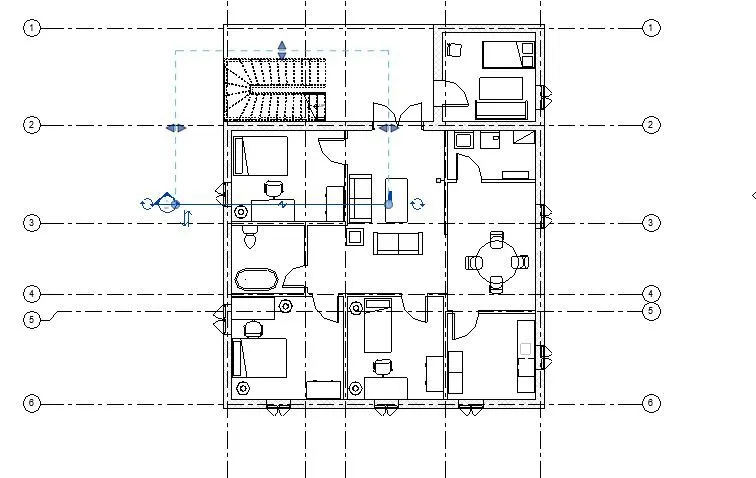
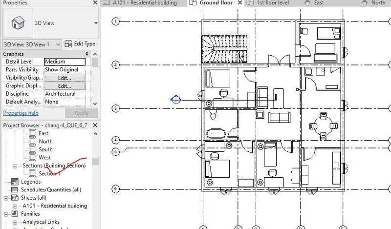
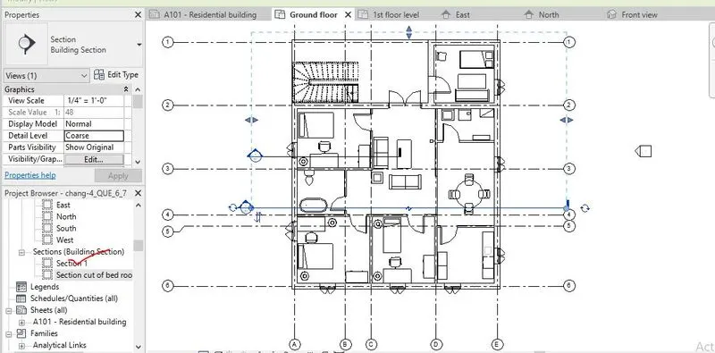
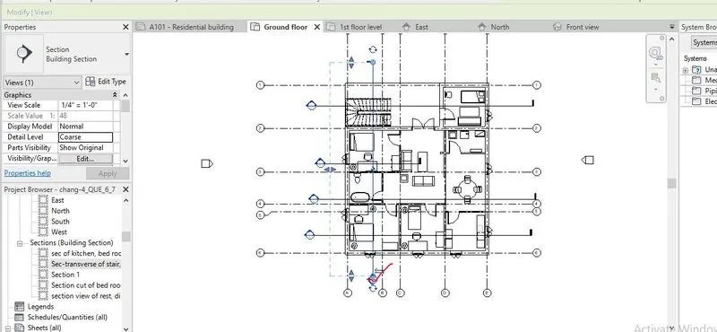
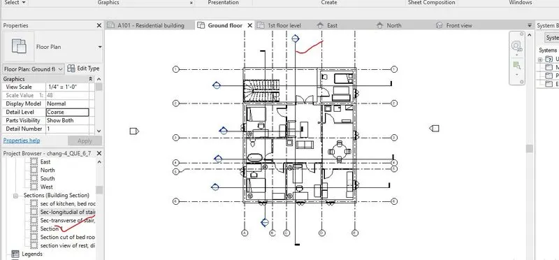
Step-2- By clicking on the selection tool from the view tab, a selection line will be opened with the direction where the requited direction can be selected as per required view.
Step-3- the selection view is named by selecting the rename option which is selected by right clicking on the correspondence view from project browser.
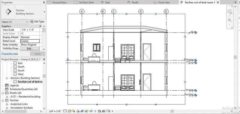
Step-4- The sectional view is viewed by clicking on the respective selection from the project browser.
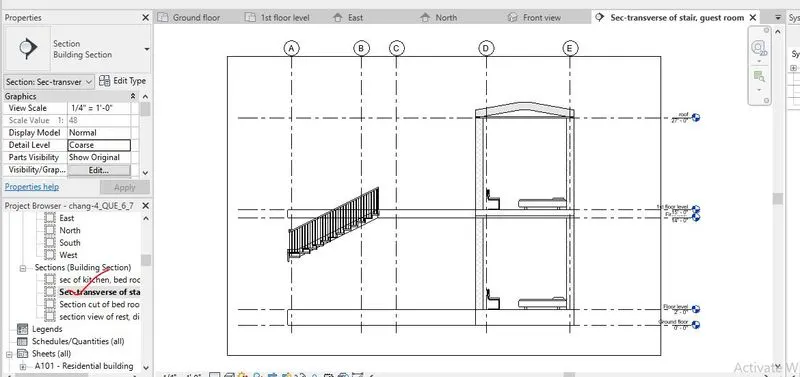
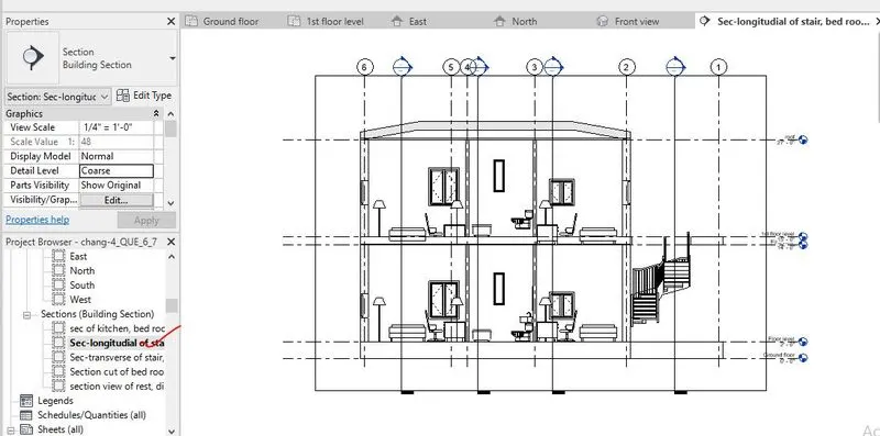
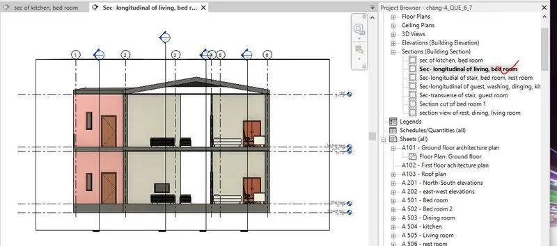
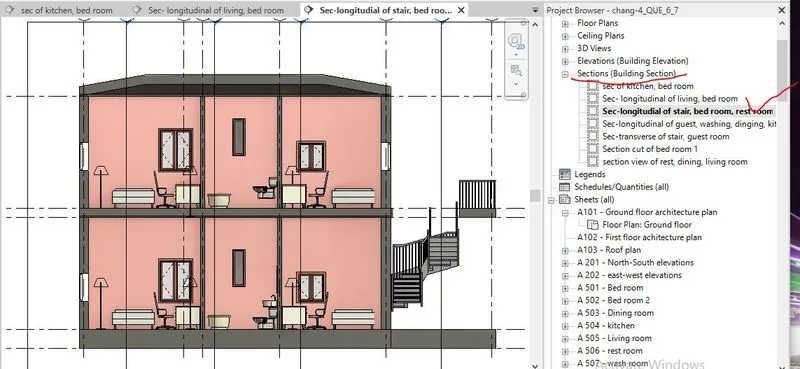
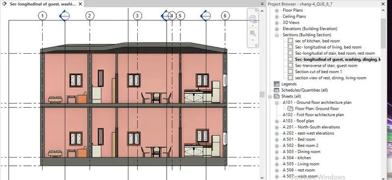
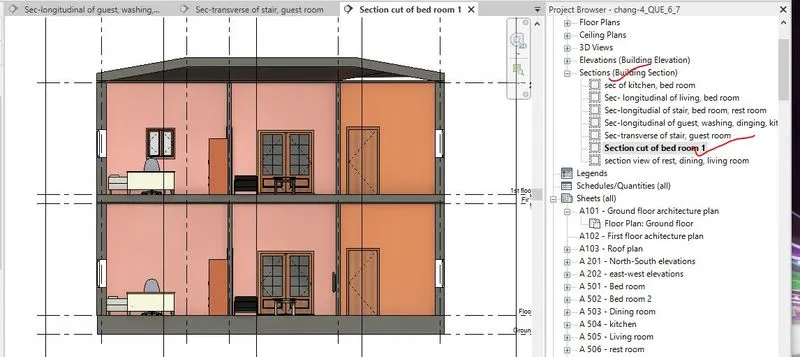
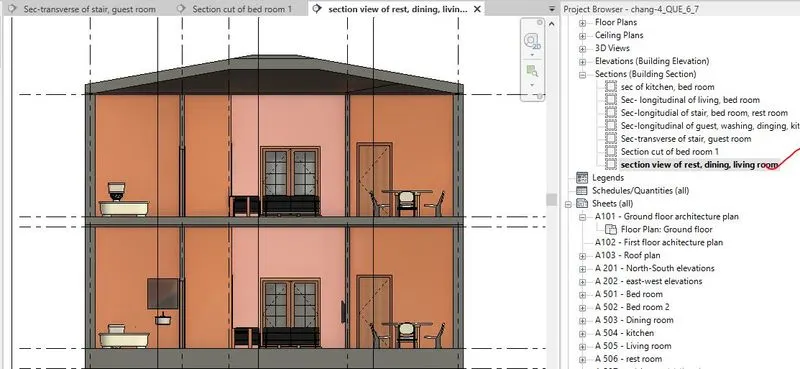
Here in this project, transvers and longitudinal section is cut of the stair, bed room, rest room, living room, dining room, kitchen.
Screenshot of obtaining section cut through each room either cutting across longitudinally or in a transverse direction is given below,

7.3 RESULTS-
The results of obtaining section cut through each room either cutting across longitudinally or in a transverse direction i.e. the .rvt file is uploaded named as 'chang-4_QUE_6_7'.
-----------------------------------------------------------------------------------------------------------------------------------------
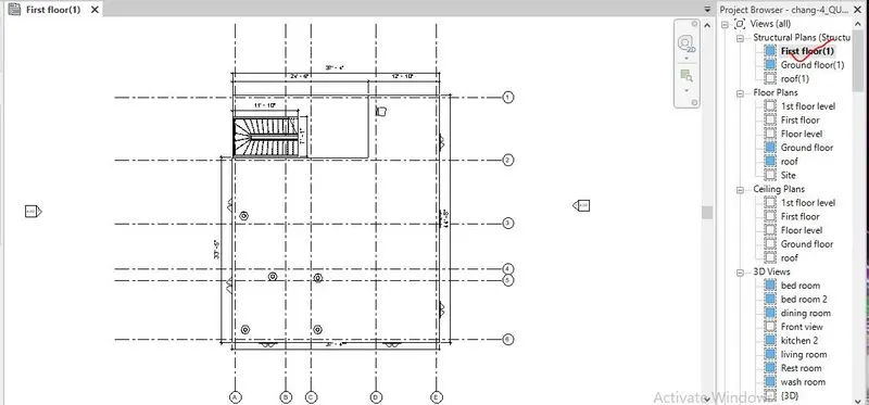
QUE-8) Classify the views, Plan Views, Section Views, and Elevation views to either Design or Documentation category using Properties browser.
-------------------------------------------------------------------------------------------------------------------------------------
8.1 AIM- To classify the views, Plan Views, Section Views, and Elevation views to either Design or Documentation category using Properties browser.
8.2 PROCEDURE- All the details procedure in classifying the views, Plan Views, Section Views, and Elevation views to either Design or Documentation category using Properties browser is discussed below,
Step-1- First the floor plan of the challenge 2 is opened by using file option from where the file is saved.
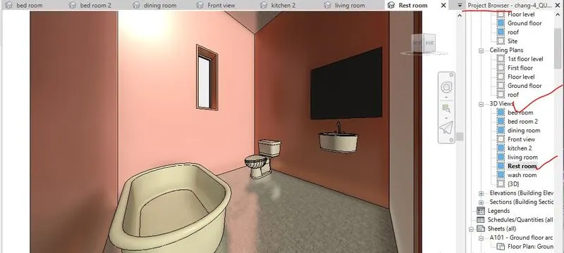
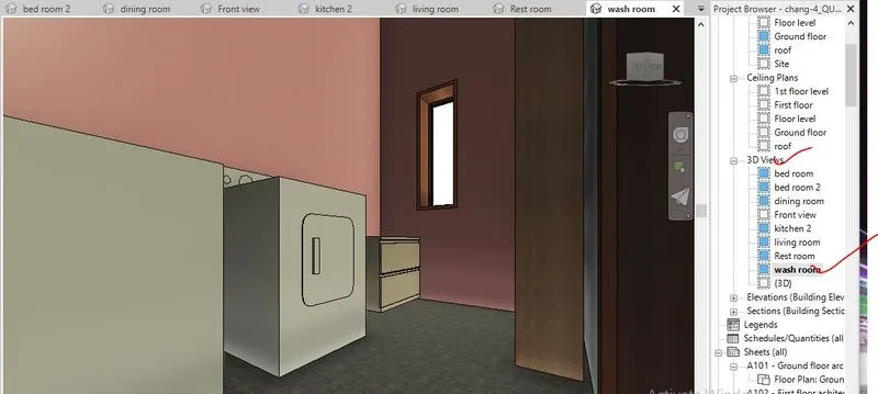
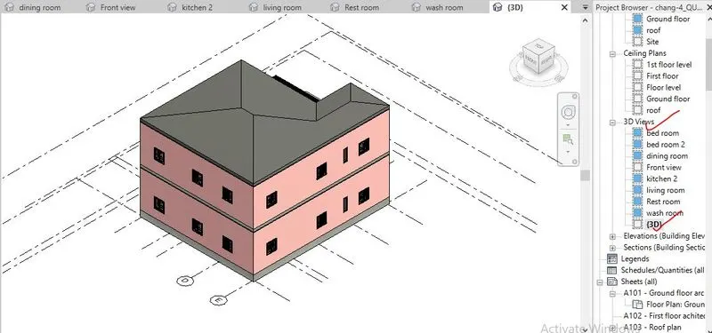
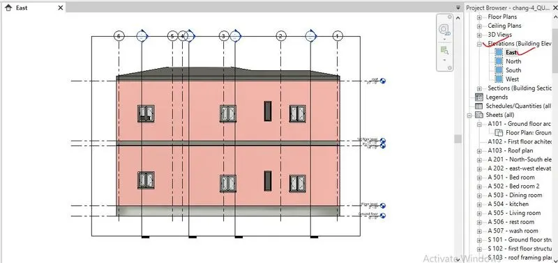
Step-2- To classify the view i.e. plan views, section views, elevation views to either design or documentations using properties browsers, the first step is to go the properties browsers.
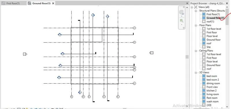
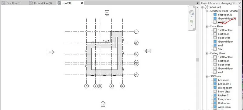
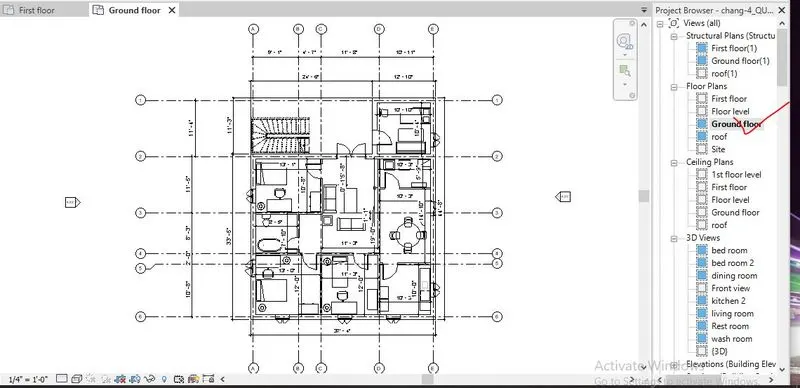
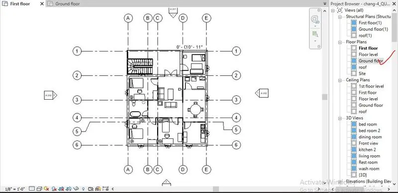
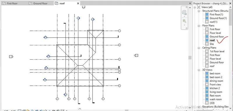
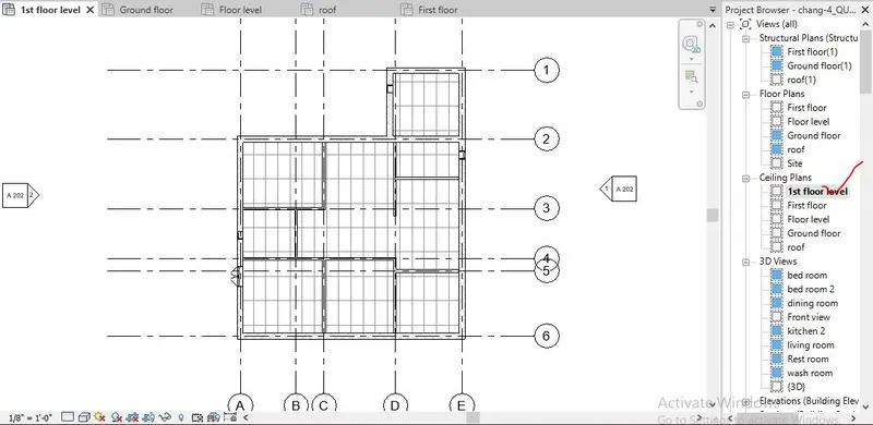
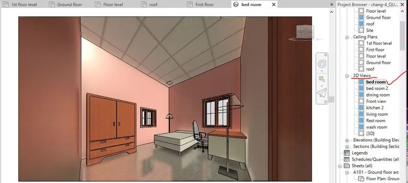
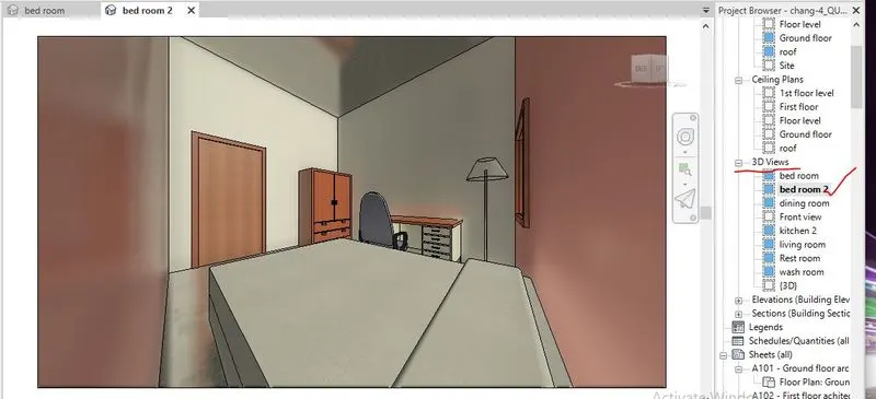
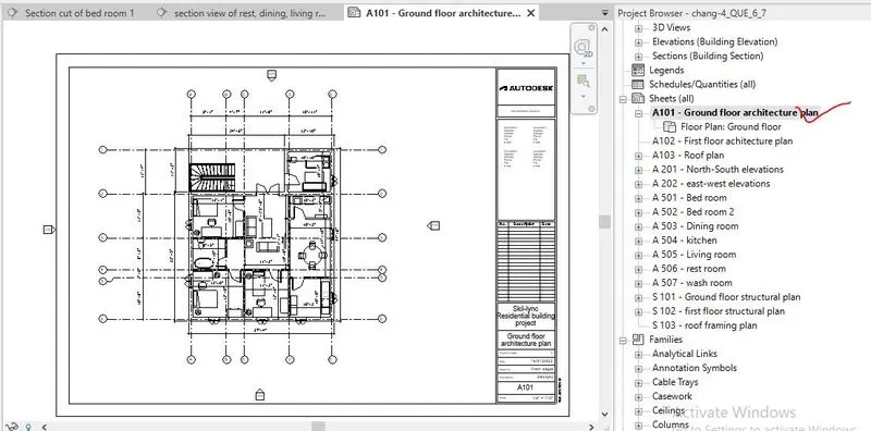
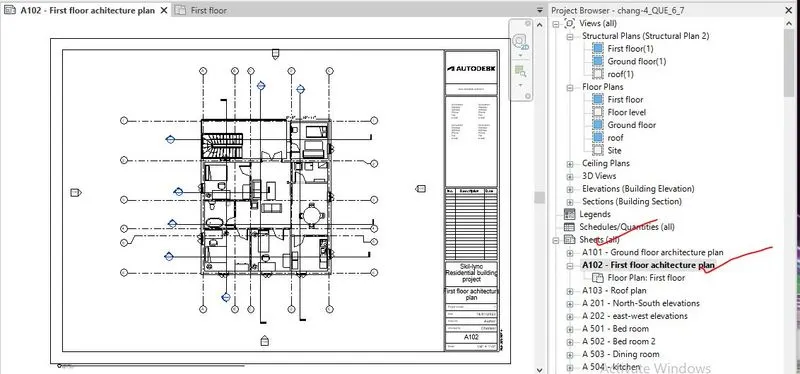
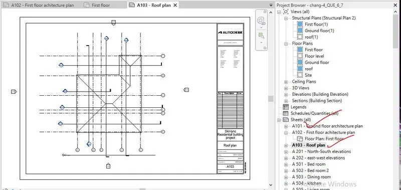
Step-3- As per the required views i.e. the structural plan, floor plan, elevation views, section views, all the view is obtained by double clicking the on views on properties browser and it appears.
Step-4- For all the views, same procedure has been followed.
Screenshot of classifying the views, Plan Views, Section Views, and Elevation views to either Design or Documentation category using Properties browser is given below,
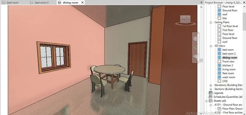
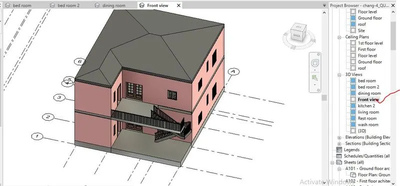
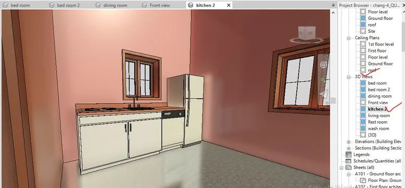
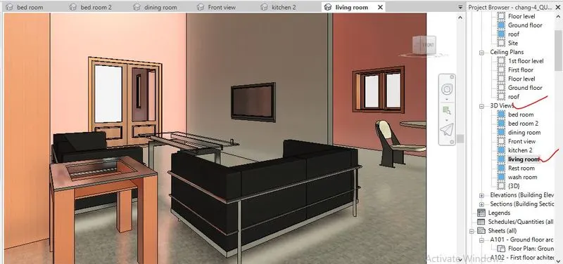
8.3 RESULTS-
The results of classifying the views, Plan Views, Section Views, and Elevation views to either Design or Documentation category using Properties browser i.e. the .rvt file is uploaded named as 'chang-4_QUE_6_7'.
-----------------------------------------------------------------------------------------------------------------------------------------
QUE-9) Using the sheet template produced create multiple sheets as follows
a. A 101- Ground Floor Architecture Plan
b. A 102- First Floor Architecture Plan
c. A 103- Roof Plan
d. S 101- Ground Floor Structural Plan
e. S 102- First Floor Structural Plan
f. S 103- Roof Framing Plan
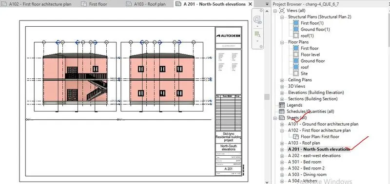
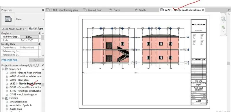
g. A-201- North-South Elevations
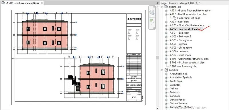
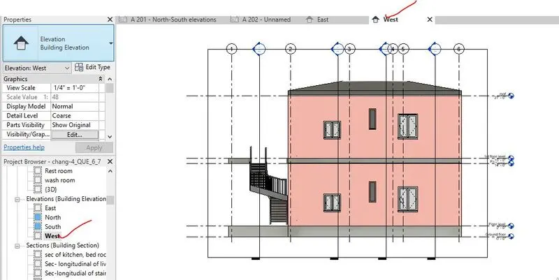
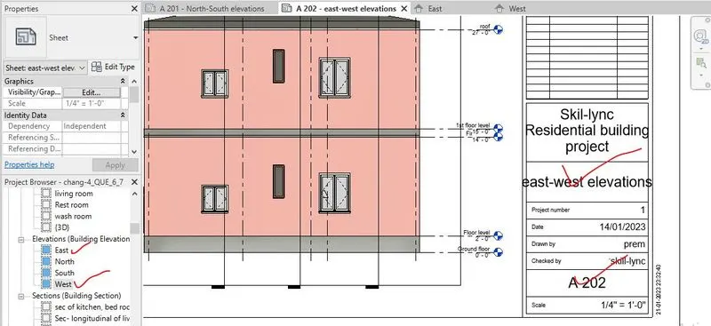
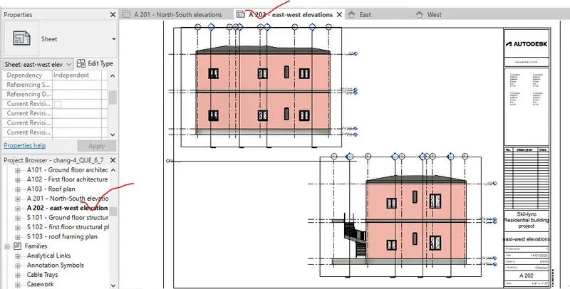
h. A-202- East-West Elevations
Add additional sheets based on the sections created in your Revit file.
-------------------------------------------------------------------------------------------------------------------------------------
9.1 AIM- To create multiple sheets for addition of the following documents and diagrams,
- A 101- Ground Floor Architecture Plan
- A 102- First Floor Architecture Plan
- A 103- Roof Plan
- S 101- Ground Floor Structural Plan
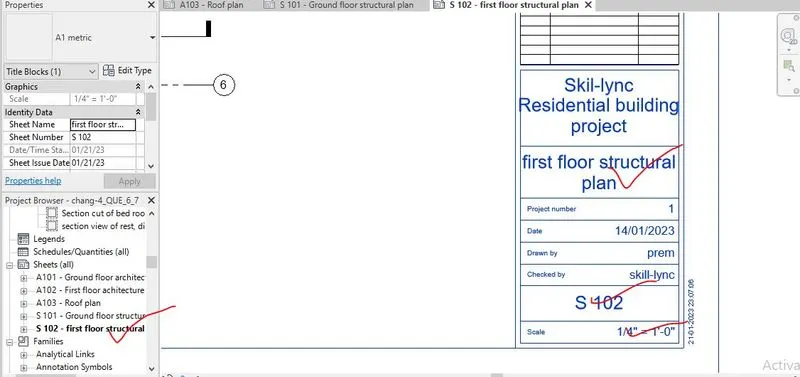
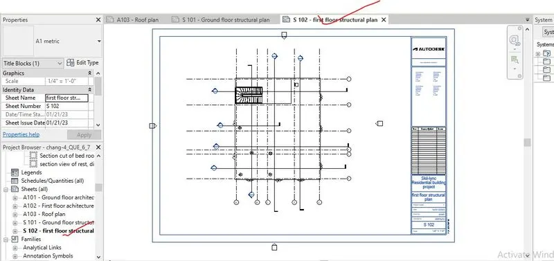
- S 102- First Floor Structural Plan
- S 103- Roof Framing Plan
- A-201- North-South Elevations
- A-202- East-West Elevations
9.2 PROCEDURE- All the details procedure in creating multiple sheets for addition of the differents documents and diagrams i.e. Ground Floor Architecture Plan, First Floor Architecture Plan, Roof Plan, Ground Floor Structural Plan, First Floor Structural Plan, Roof Framing Plan, North-South Elevations and East-West Elevations is discussed below,
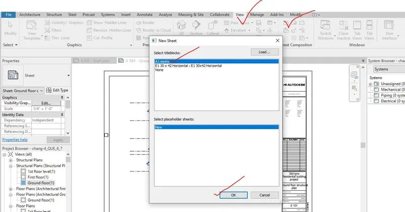
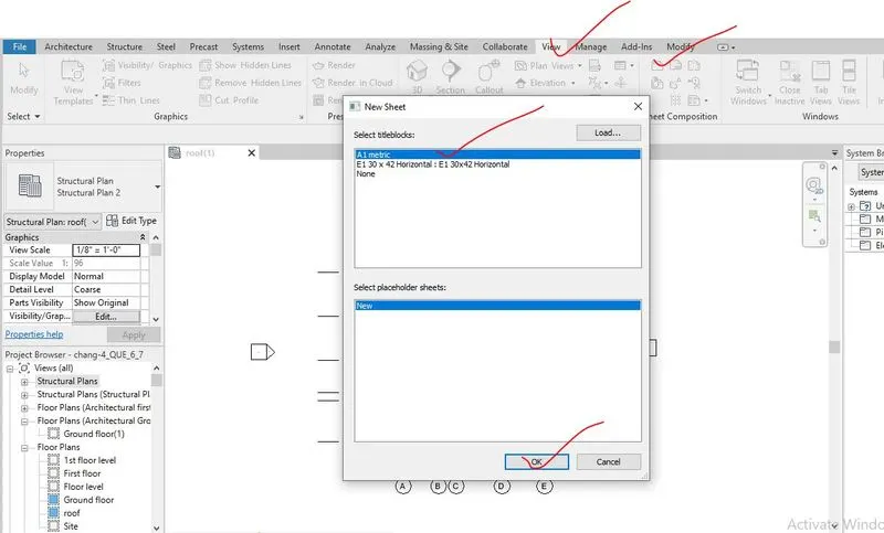
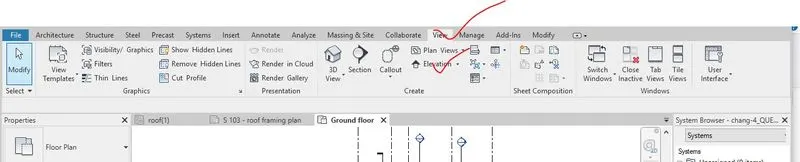
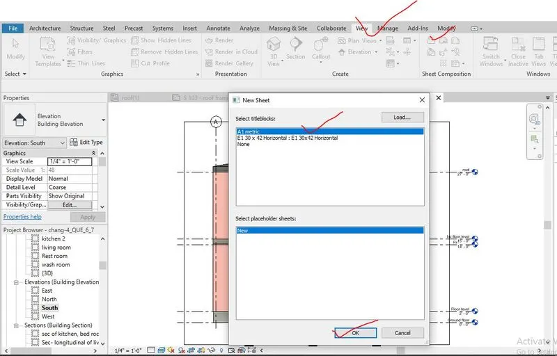
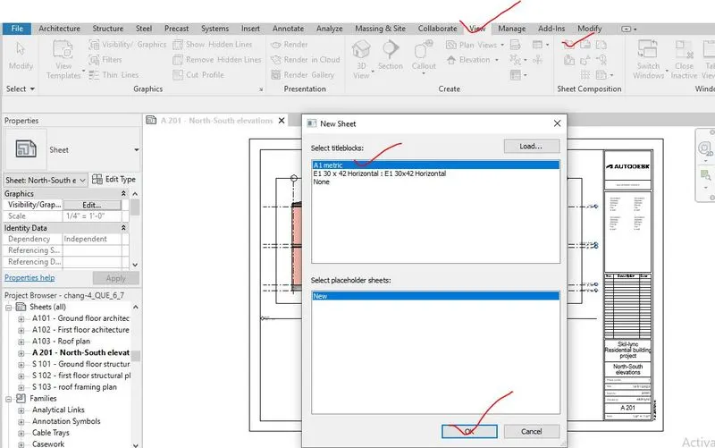
Step-1- for opening of the templates to add the documents or design diagram, by clicking on the view tab, the sheet tools are selected to add the appropriate view of the projects.
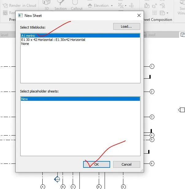
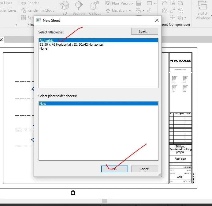
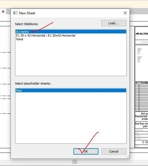
Step-2- After selecting the sheet tool, a pop up box will open where the title-blocks can be loaded as per the required size. Here the A1 matric has been chose from the title blocks.
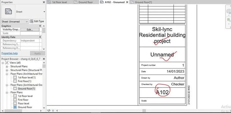
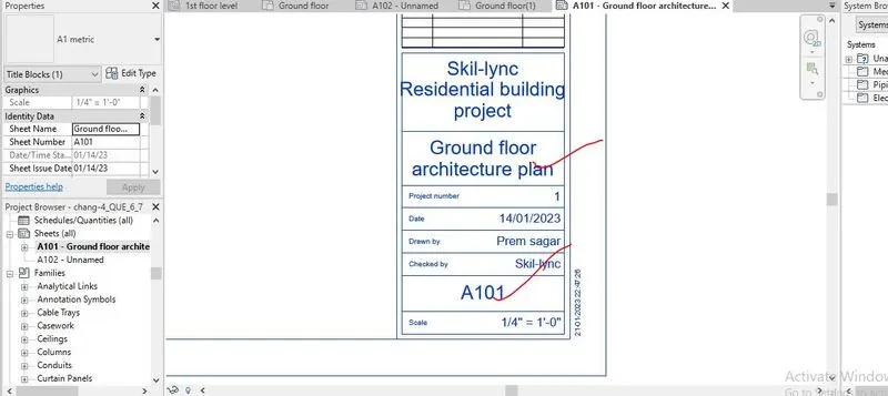
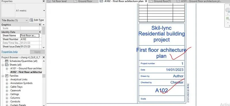
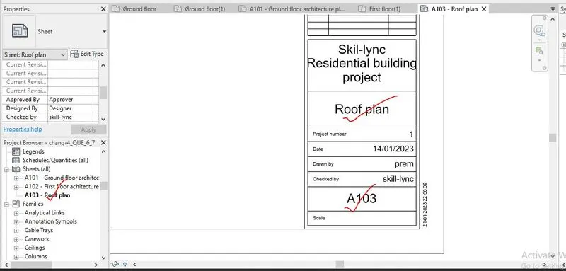
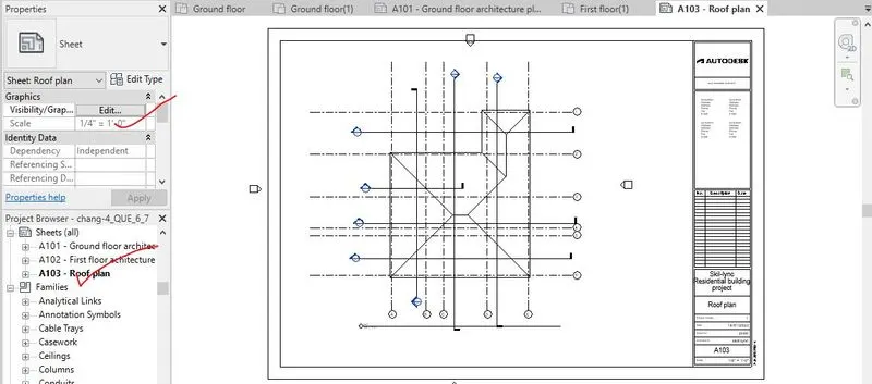
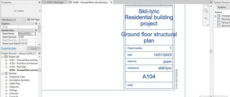
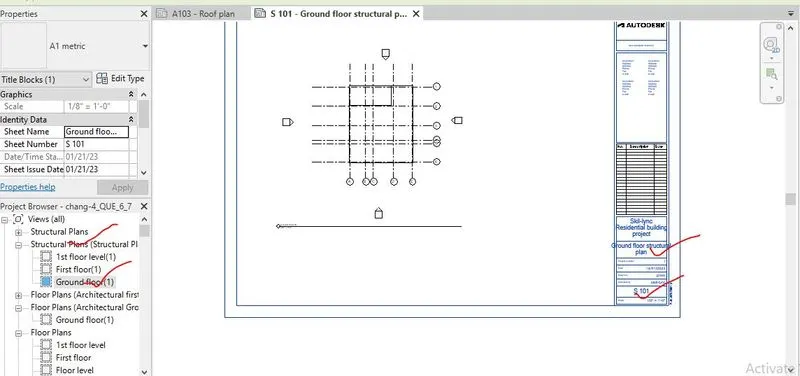
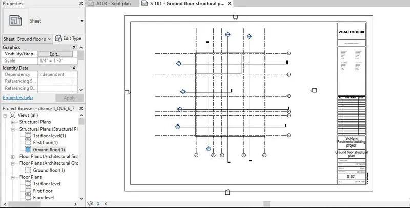
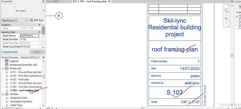
Step-3- After selection of the A1 matric sheet, an A1 size sheet has been open where the project information is updated, here in this project, the project name, sheet name and the diagram name has been named as per the given data that is given below,
- A 101- Ground Floor Architecture Plan
- A 102- First Floor Architecture Plan
- A 103- Roof Plan
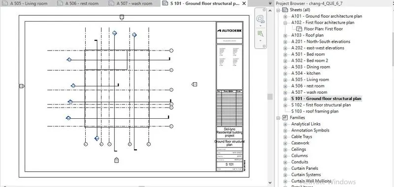
- S 101- Ground Floor Structural Plan
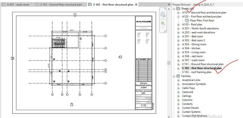
- S 102- First Floor Structural Plan
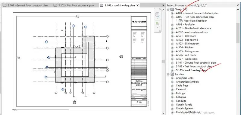
- S 103- Roof Framing Plan
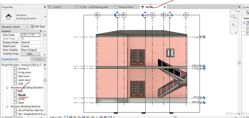
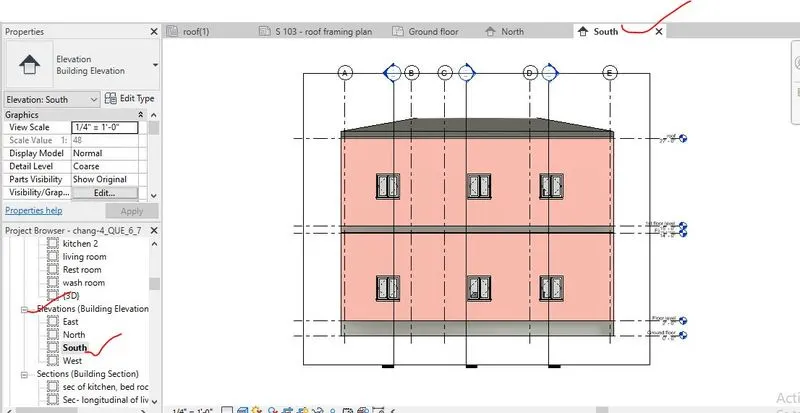
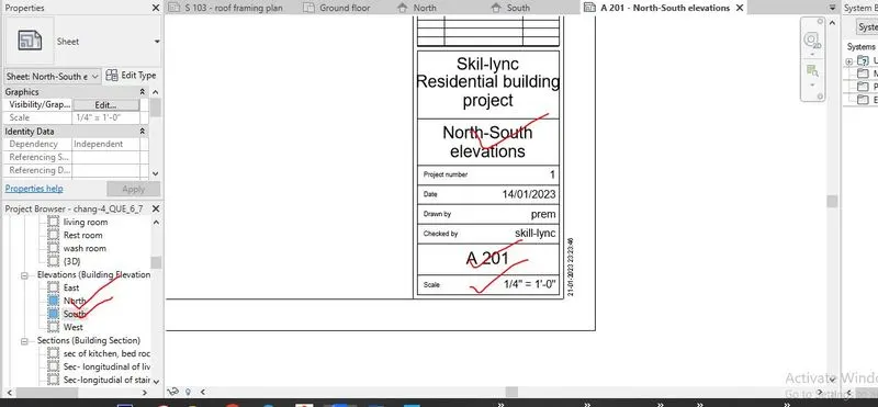
- A-201- North-South Elevations
- A-202- East-West Elevations
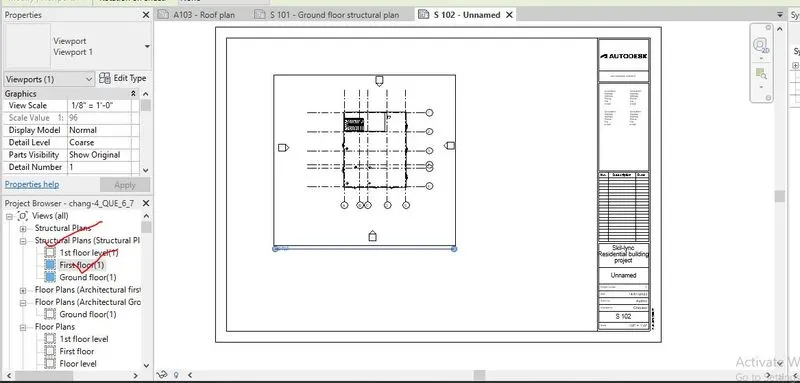
For every insertion of the diagrams and documents, a new sheet is created as per the required size and then diagram name, sheet name is edited.
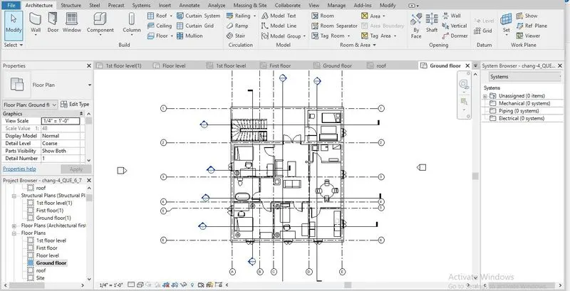
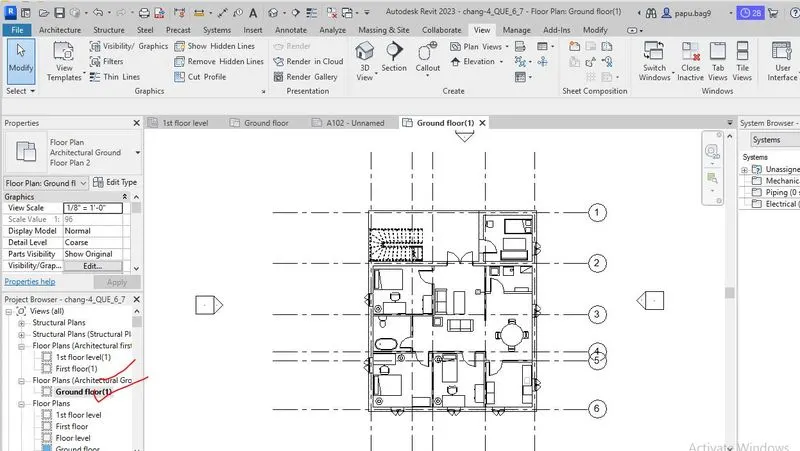
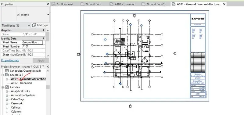
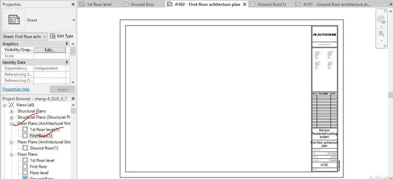
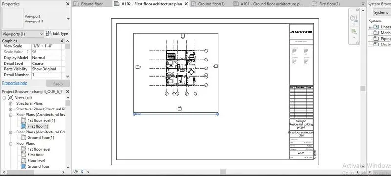
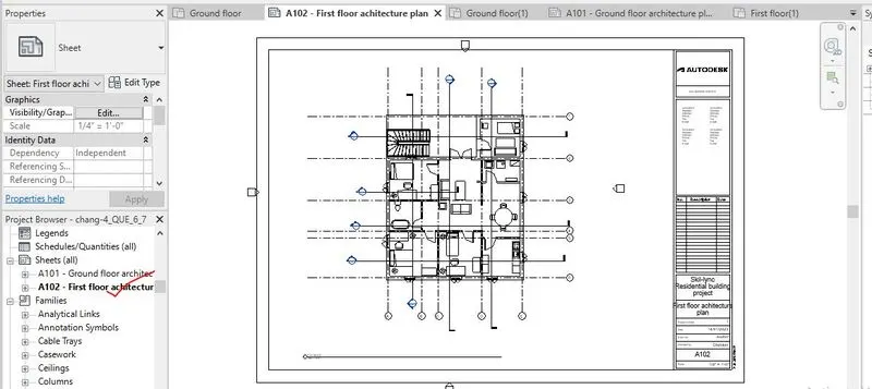
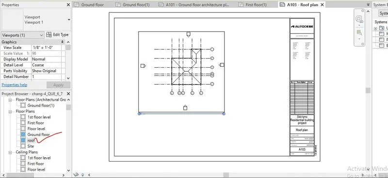
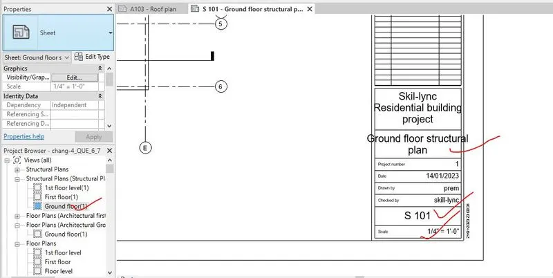
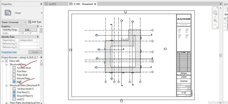
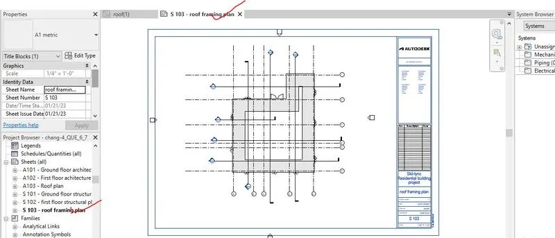
Step-4- From the project browser, the floor plan or any other project documents which is asked to add in the sheet i.e. Ground Floor Architecture Plan, First Floor Architecture Plan, Roof Plan, Ground Floor Structural Plan, First Floor Structural Plan, Roof Framing Plan, North-South Elevations and East-West Elevations, are added to the sheet by select and dragging to the suitable place in the sheet, scale, an appropriate size is adjusted.
For every insertion of the diagrams and documents, a new sheet is created as per the required size and then diagram name, sheet name is edited.
Screenshot of creating multiple sheets for addition of the differents documents and diagrams i.e. Ground Floor Architecture Plan, First Floor Architecture Plan, Roof Plan, Ground Floor Structural Plan, First Floor Structural Plan, Roof Framing Plan, North-South Elevations and East-West Elevations is given below,


9.3 RESULTS-
The results of creating multiple sheets for addition of the differents documents and diagrams i.e. Ground Floor Architecture Plan, First Floor Architecture Plan, Roof Plan, Ground Floor Structural Plan, First Floor Structural Plan, Roof Framing Plan, North-South Elevations and East-West Elevations i.e. the .rvt file is uploaded named as 'chang-4_QUE_6_7'.
-----------------------------------------------------------------------------------------------------------------------------------------
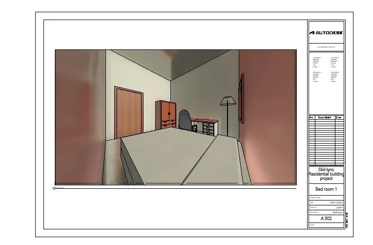
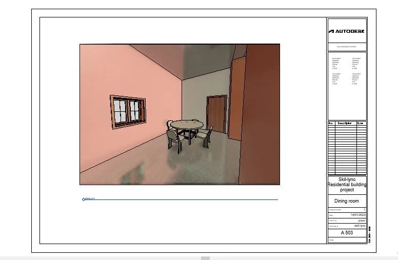
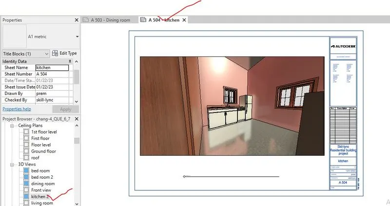
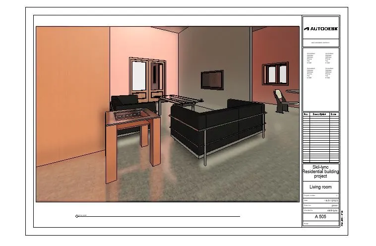
QUE-10) Create a camera-specific view or a 3D view in each room ( living, dining, bedroom). Based on the views create a new set of sheets starting A-501 (you can add as many sheets after, 502, 503.. n)to place the 3D view images. Produce the sheets as a part of project drafting.
-------------------------------------------------------------------------------------------------------------------------------------
10.1 AIM- To create a camera-specific view or a 3D view in each room ( living, dining, bedroom, kitchen, rest room, bed room etc) based on the views create a new set of sheets to place the 3D view images.
10.2 PROCEDURE- All the details procedure in creating a camera-specific view or a 3D view in each room ( living, dining, bedroom, kitchen, rest room, bed room etc) based on the views create a new set of sheets to place the 3D view images is discussed below,
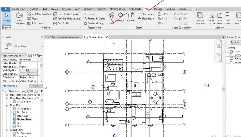
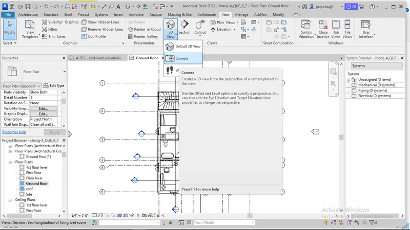
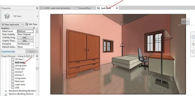
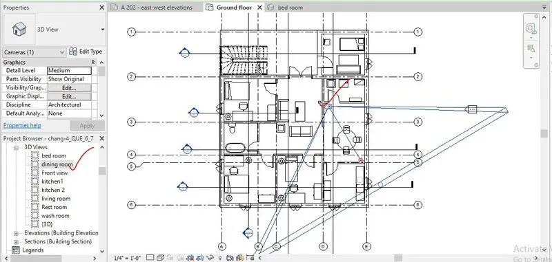
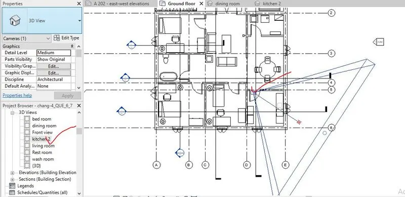
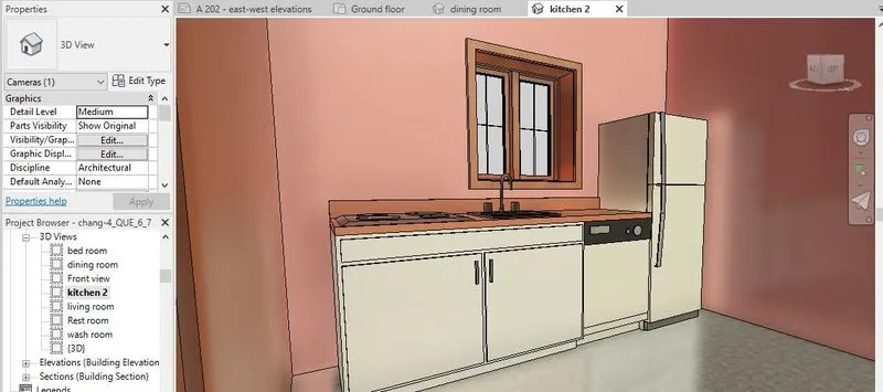
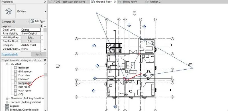
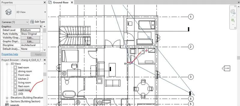
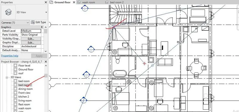
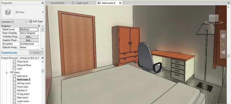
Step-1- To see the 3D image of the all the room in the building, the 3d view is to obtained. For this the camera view is selected from the view tab.
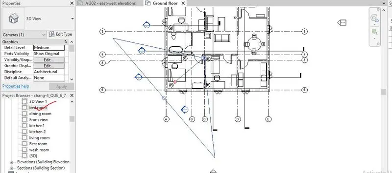
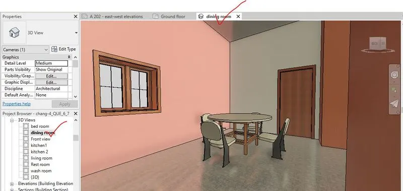
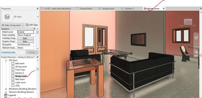
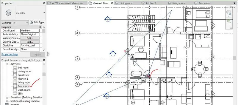
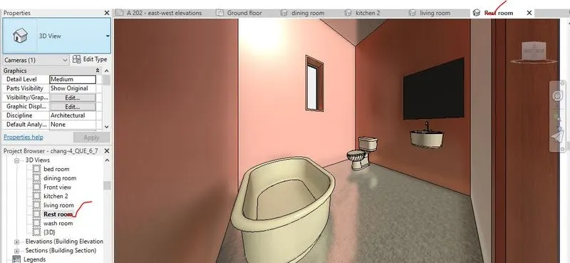
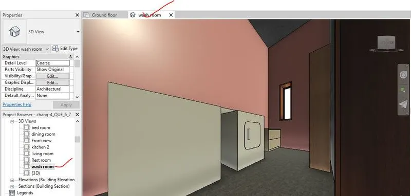
Step-2- After selection of the camera view, the camera is placed at the bed room, living room, dining room, rest room, kitchen, wash room.
Step-3- After placing of the camera, the height of the camera and target of the camera is selected as per the suitability and visibility of the room. Here in the project,
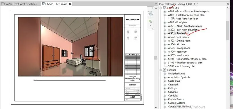
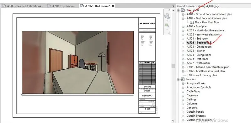
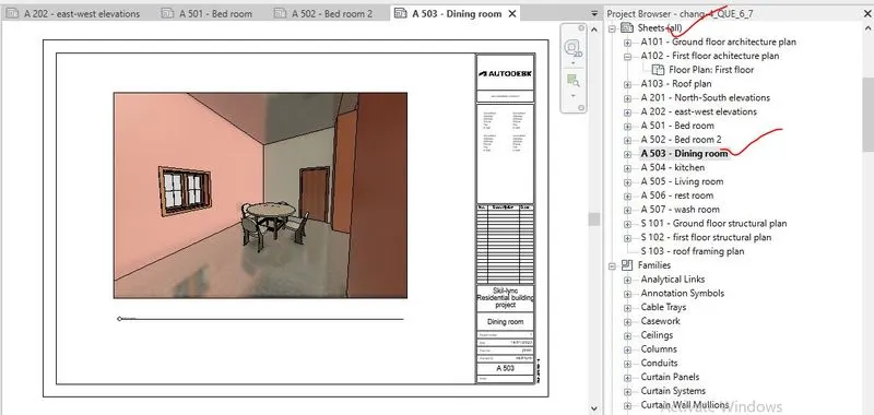
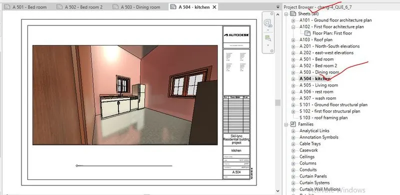
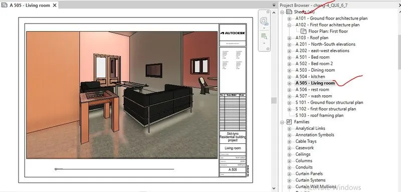
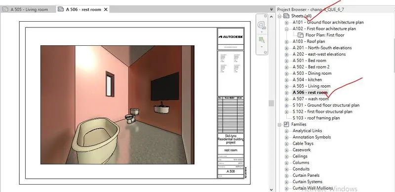
Step-4- from the properties browser, the name of the 3D views is changed as per the respective room and the views that has been taken by using the camera i.e. bed room, bed room 2, living room, dining room, rest room, kitchen, wash room.
Step-5- to add all the 3D views to the sheet, the A1 matric sheet is chosen from the view tab.
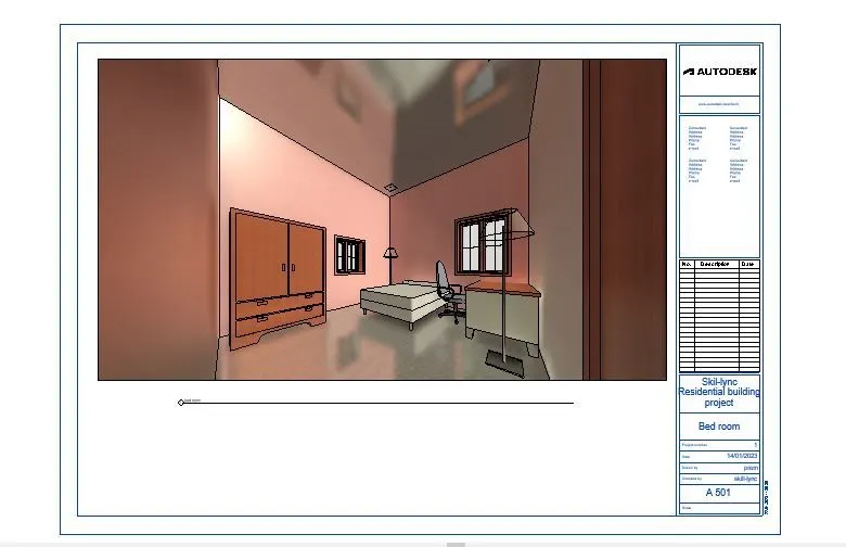
Step-6-After choosing the A1 matric type sheet form the sheet, the respective 3D views is add the sheet by clicking and dragging the appropriate place in the sheet with proper scale and size.
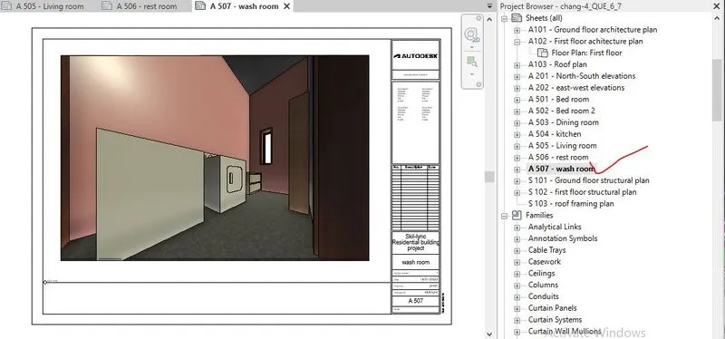
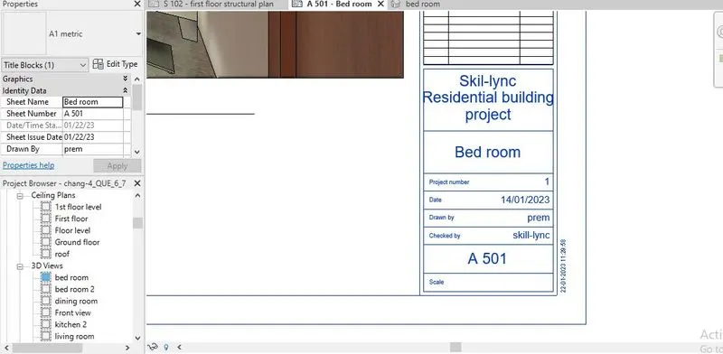
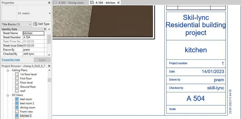
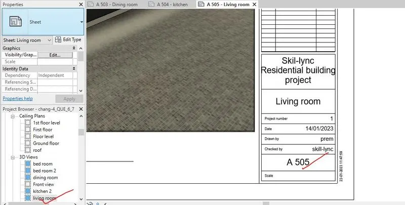
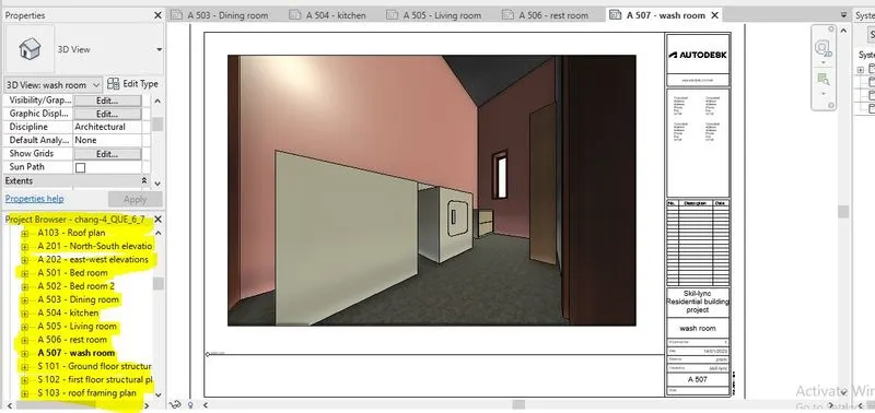
Step-7- After placing of the 3D views, the name of the sheet according to their respective room is changed and the numbered to every 3D views which is given below whatever is named and numbered.
- A 501-Bed room
- A 502-Bed room 2
- A 503-Dining room
- A 504-Kitchen
- A 505- Living room
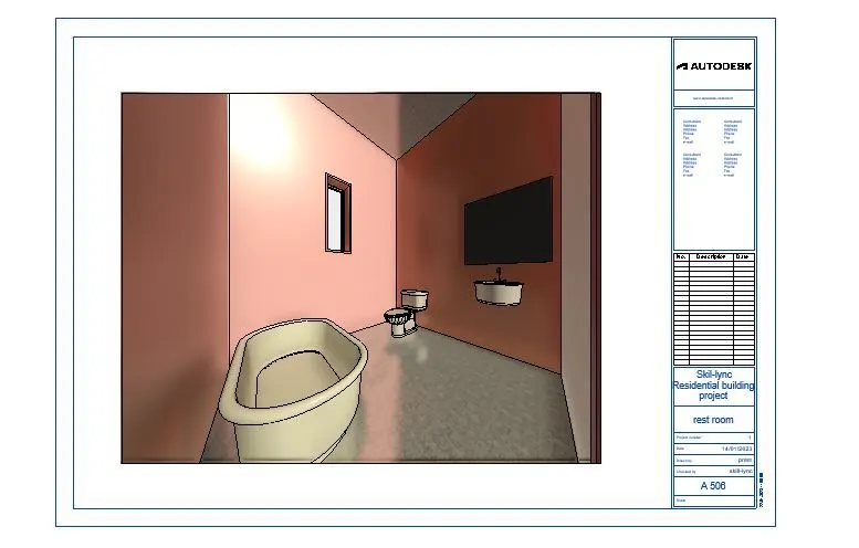
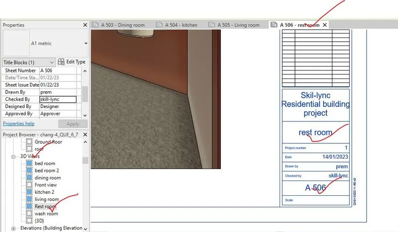
- A 506-Rest room
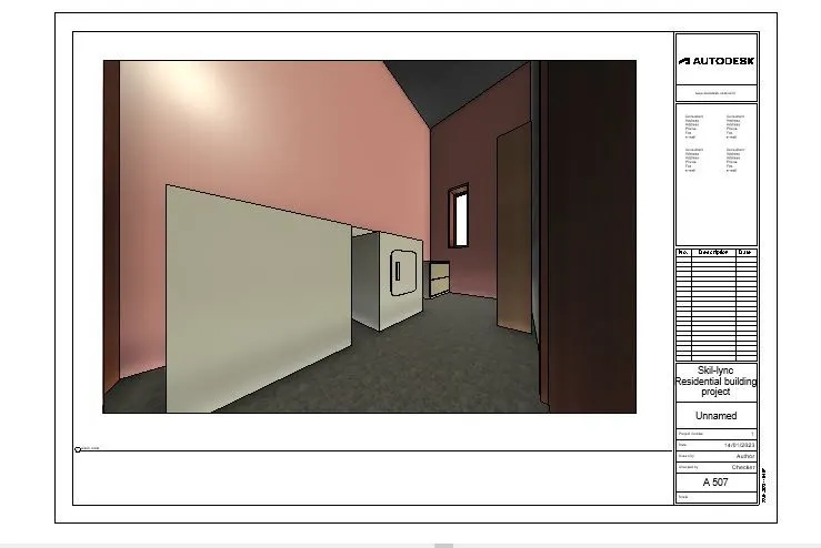
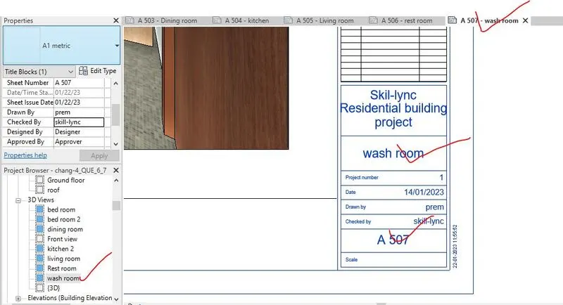
- A 507-Wash room
Screenshot of creating a camera-specific view or a 3D view in each room ( living, dining, bedroom, kitchen, rest room, bed room etc) based on the views create a new set of sheets to place the 3D view images is given below,

10.3 RESULTS-
The results of creating a camera-specific view or a 3D view in each room ( living, dining, bedroom, kitchen, rest room, bed room etc) based on the views create a new set of sheets to place the 3D view images i.e. the .rvt file is uploaded named as 'chang-4_QUE_7'.
-----------------------------------------------------------------------------------------------------------------------------------------