Reinforcement Detailing of Beams from ETABS output
1.1Aim of the project- To know the design of RC beam using ETAB analysis, the basics of beam reinforcement detailing with respect to primary standards using AUTOCAD and to ensure the ductility reinforcement required by IS 13920-2016 satisfied in ETABS design.
1.2 Introduction-
- Plan and 3d elevation of G+4 building with beam size and column size is given below,
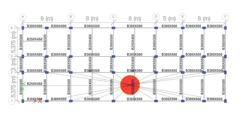
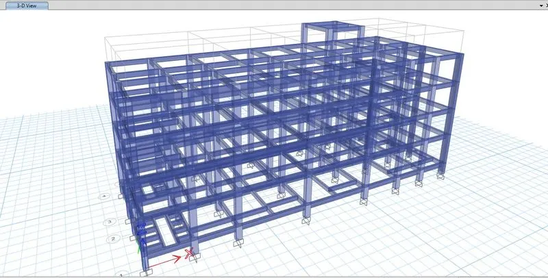
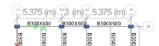
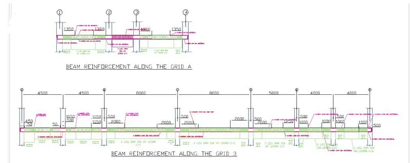
- 3 span continuous beam along grid A of the building plan is given below,
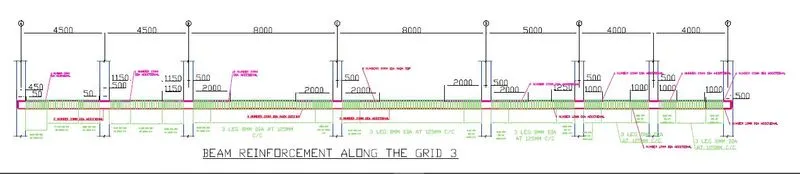
- 7 span continuous beam along grid 3 of building plan is given below,

2.1 Procedure-
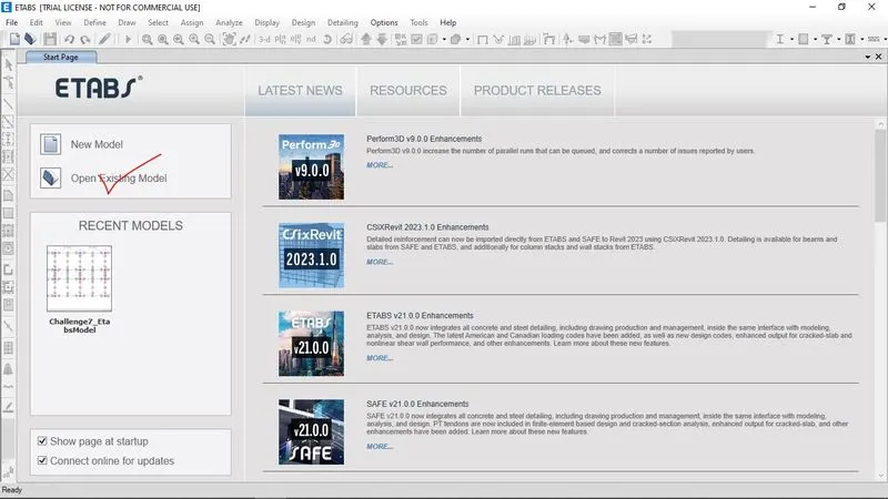
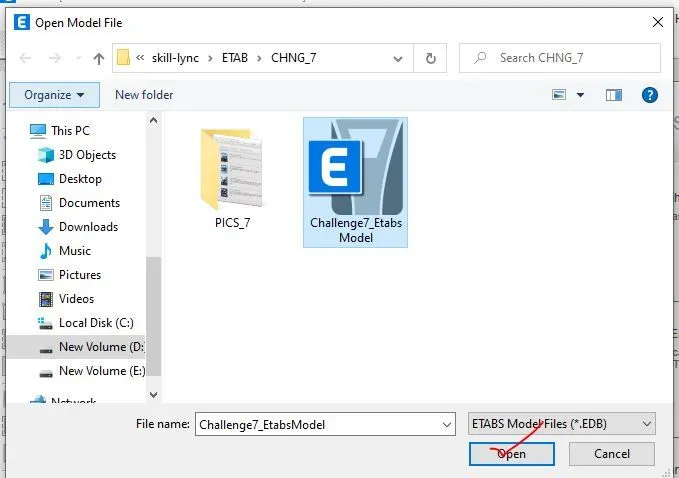
Step-1 – Firstly the ETABS file has been opened and every material properties and load properties has been checked.
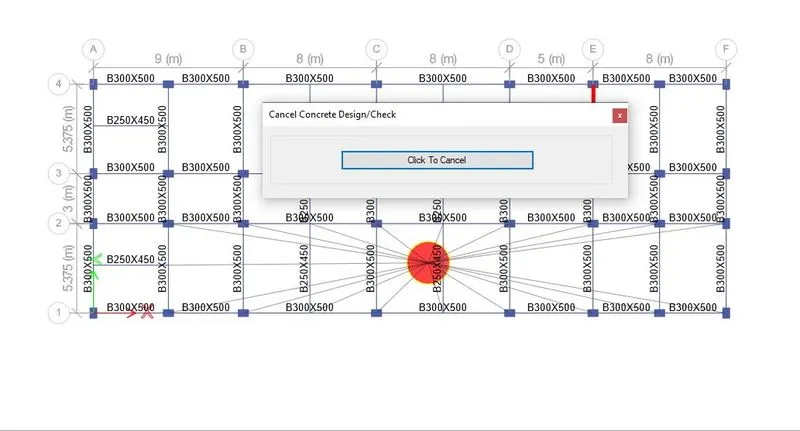
Step-2- After verification of material properties and load properties, the model has been analysed by F5 bottom or by directly clicking on run analysis bottom on ETABS.
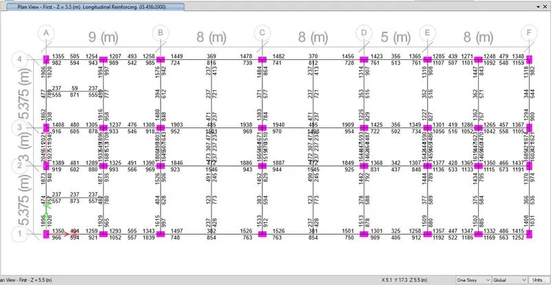
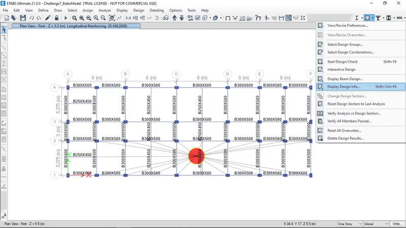
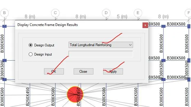
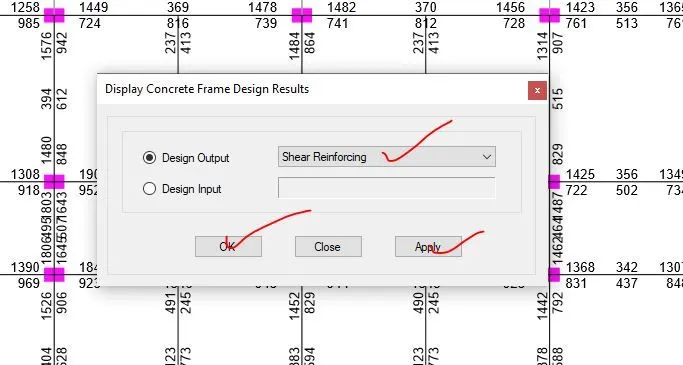
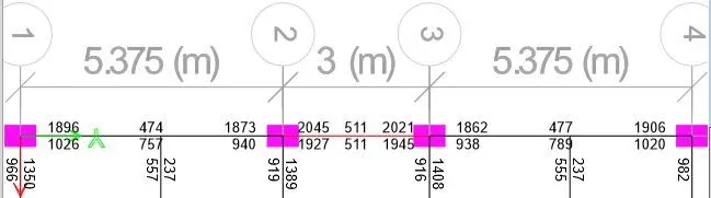
Step-3- After completion of analysis, the analysed model has been design by clicking on the concrete frame design bottom which designs the longitudinal reinforcement and shear reinforcement for all the load combination of all the members in the model which can be checked by clicking on drop down bottom of concrete frame design and the by clicking on display design info.
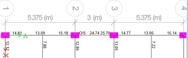
The amount longitudinal reinforcement and shear reinforcement has been given below,
Amount of longitudinal reinforcement
Amount of shear reinforcement
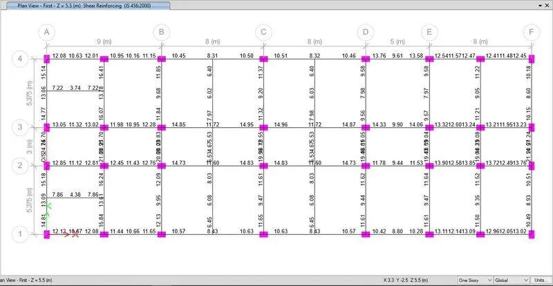
Step-4- Design details i.e. flexural details and shear details for all the load combination of every members in the model can be checked by right clicking on the required members and directly the designs can be access.
Step-5 After finding the design details, then the given grids has been done the detailing.
2.2 All the step wise screen shots in analysing and designing the concrete frame structure is given below,




3.1 Results and Discussion
- Detailing rule of reinforcement concrete members
- Minimum reinforcement for shrinkage and temperature
- Reinforcement required for limiting cracking width
- Ultimate limit state design rebar reinforcement
- Ductility rebar reinforcement
RC beam detailing is chose whichever is greater among above condition 1, 2, 3 and 4.
- Minimum longitudinal reinforcement as per IS 13920-2016 clause 6.2.1.
AS= 360 mm2
- Minimum shear reinforcement as per IS 456-2000 clause 26.5.1.6 assuming 1 meters spacing in the formula,
ASV= 332 mm2
- Development length as per IS 456-2000 clause 26.2.1
Ld= 41 × diameter of bar
For 20mm dia, Ld= 41 × 20mm= 820mm
For 25 mm dia, Ld= 41 × 25mm= 1025mm
For 12mm dia, Ld= 41 × 12mm= 492mm
- longitudinal reinforcement for Grid A
- longitudinal reinforcement for Grid 3
- Shear reinforcement for Grid A
- Shear reinforcement for Grid 3
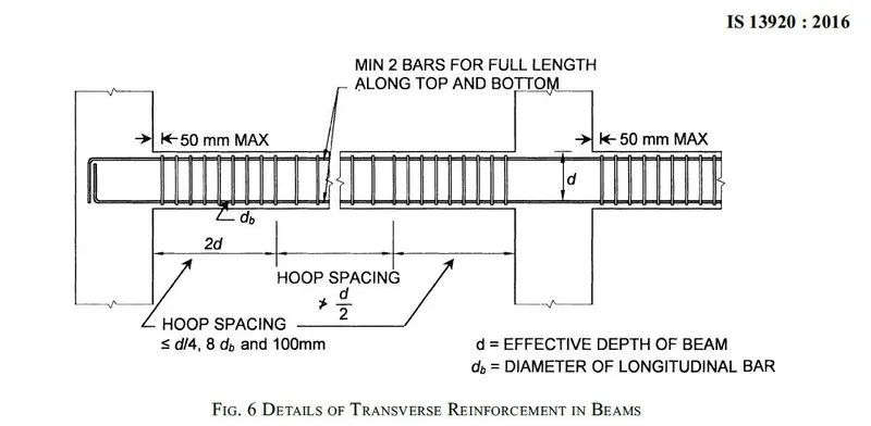
- Additional reinforcement for guideline from IS 13920-2016
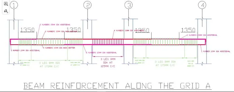
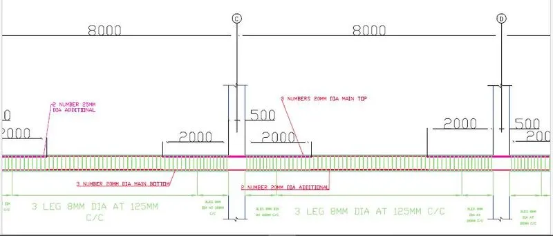
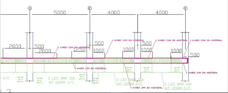
4.1 After getting the value of longitudinal reinforcement and shear reinforcement for grid A and grid 3, the detail reinforcement has been drafted using AUTOCAD which is given below,
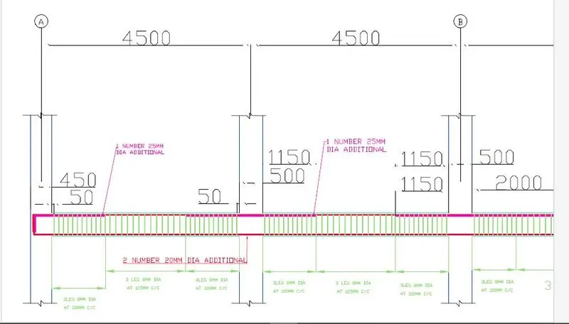
5.1 Reasons for failure of the middle span along grid A
- Failure is due to shear stress occur due to shear force and torsion together which exceeds maximum allowed.
- Possible ways to resolve this issue.
- Shear capacity of the concrete which can be increased by improving grade of concrete.
- As this beam fail in shear, this could be mitigate by providing higher numbers of stirrup.
- Shear stress developed due to shear force and torsion can be reduced by increasing the size of the beam.
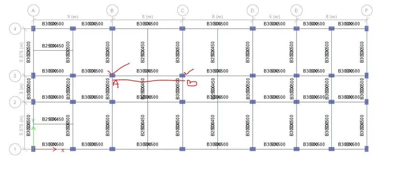
6.1 Calculation value of the maximum shear force in the span in both the continuous beams in grid 3 of first floor, as per clause 6.3.3 (b) in IS 13920 – 2016
Beam in grid 3 from first floor has been chosen, that is given below,
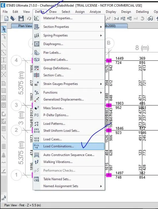
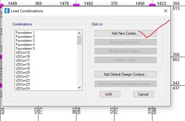
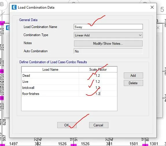
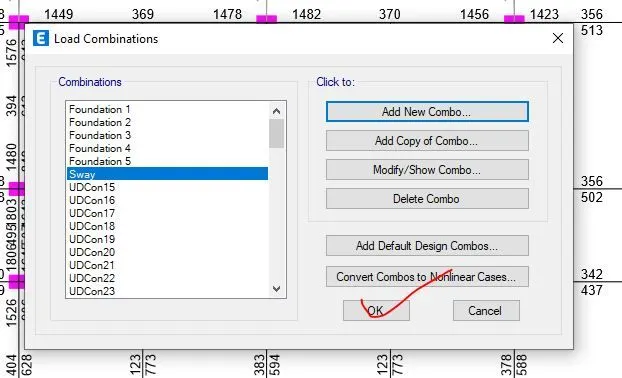
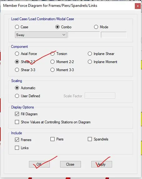
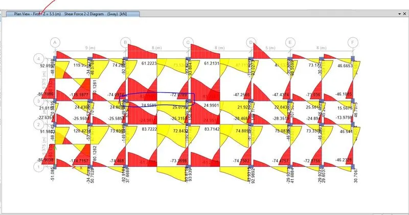
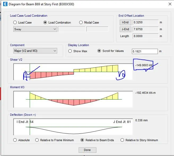
6.2 All the step wise screen shots of Procedure in analysing and designing of the model with new load combination for sway to find out the shear force for sway by taking factor of safety for 1.2 for dead load and live load,


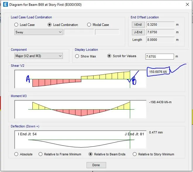
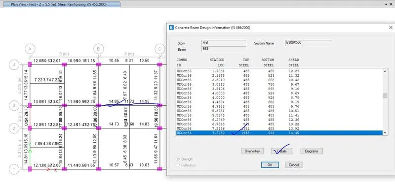
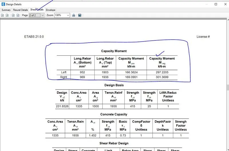
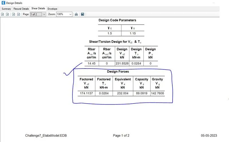
6.3 Calculation value of the maximum shear force in the span in both the continuous beams in grid 3 of first floor, as per clause 6.3.3 (b) in IS 13920 – 2016,
As per IS 13920-2016 clause 6.3.3 (b)
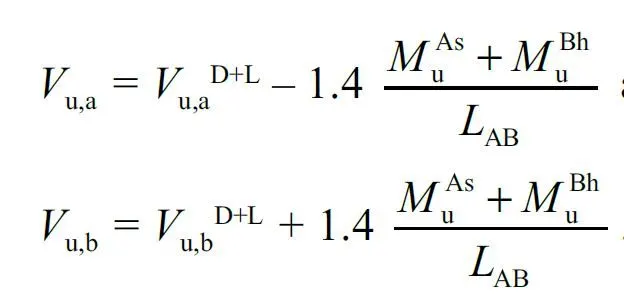
For sway to right, shear force is given by,
For sway to left, shear force is given by,
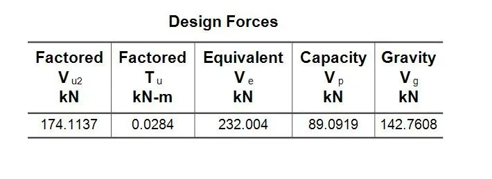
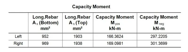
After the analysis and design of the concrete frame, we get,
From the above results, we found that,
Va,uD+L = 149.0603 kN
Vb,uD+L = 150.6876 kN
MuAs= 166.3624 kN-m
MuAh= 297.2205 kN-m
MuBs= 169.0981 kN-m
MuBh=301.3699 kN-m
LAB= 7500 mm= 7.5 m
For sway to right, shear force is equal to,
Va,u= `149.0603- (1.4×(166.3624+301.3699)/( 7.5))` = 61.75 Kn
Vb,u= `150.6876 + (1.4×(166.3624+301.3699)/( 7.5))` = 237.0 kN
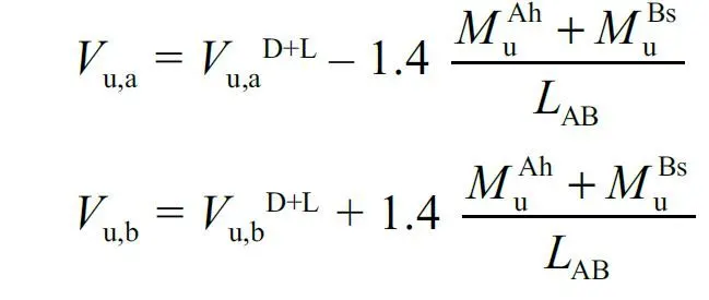
For sway to left, shear force is equal to,
Va,u= 149.0603- (1.4*(297.2205 +169.0981)/( 7.5)) = 62.01 Kn
Vb,u= `150.6876 + (1.4×(297.2205 +169.0981)/( 7.5))` = 237.733 Kn
From the above data, higher value is considered, i.e.
Va,u=62.01 Kn
Vb,u=237.733 Kn
Existing shear capacity in beam as per IS 456-2000 clause 40.4 i.e.

Where, fy= 415 N/mm2
Asv= 150.797 mm2
d= 470 mm
SV= 100 mm
Vus=`((0.87×415×150.797×470)/100)` =25589270 N= 255.893 kN
Hence the shear force in the drawing is Ok as Va,u and Vb,u are less than Vus.
NOTE-
The results in analysing and designing of the buildings as per the given data by using ETAB i.e. the .edb file named as “Challenge7_EtabsModel” and detailing of reinforcement for grid A and grid 1 which has been drafted in AUDOCAD i.e. dwg file named as “Chng_7_beam_REINFORCEMENT” have been uploaded below.