Creation of geometries by Coordinate system methods using AutoCad
ANS. 1. Aim and introduction
1.1 Aim of the challenge: - Creation of the geometries from picture of P1 to P2 using all the coordinates system methods by using line tool to create the geometries and circle tool also and for other images P4, P5, P7, P8, P9, P10 by using any one of the three coordinate methods.
Creation of the civil related profile and trusses using any one of the three coordinate methods.
1.2 Introduction: - Coordinates are the major part of the any type of the drawing which describe the location and position of any points or objects that makes the drawing perfect to study and find the location.
There are three type of coordinates system. That is given below,
- Absolute coordinates
- Relative coordinates
- Relative rectangular coordinates
- Relative polar coordinates
- Direct distance entry coordinates system.
1.3 Procedures to draft image using above three coordinates methods.
Before drafting of the images, creation of the new drawing should be done, as per challenge, imperial unit system should be chosen.
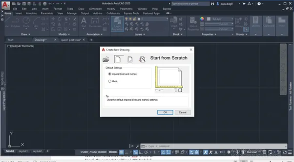
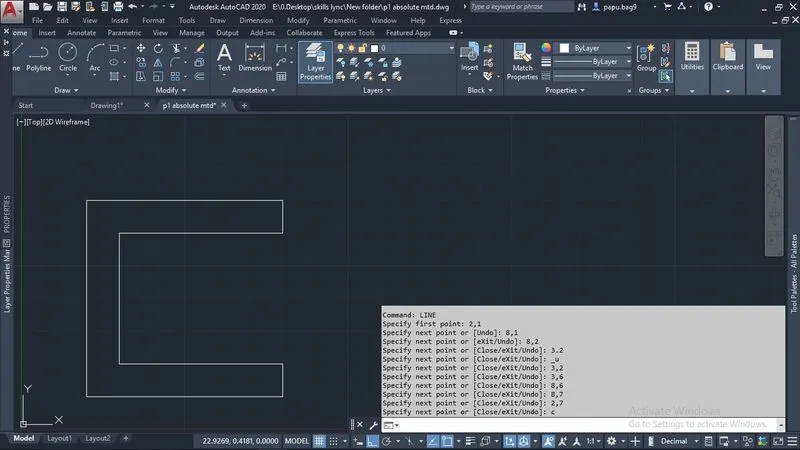
1.3.1 Procedures to draft the picture P1 using absolute coordinate system
Choose the line tool (use command L enter and ensure that the Dynamic input button is not chosen)
LINE specify the first point: 2,1
(X=2, and Y=1)
Specify the next point or [Undo]: 8,1
(X=8, and Y=1)
Specify the next point or [Undo]: 8,2
Specify the next point or [Close/ eXit/ Undo]: 3,2
Specify the next point or [Close/ eXit/ Undo]: 3,6
Specify the next point or [Close/ eXit/ Undo]: 8,6
Specify the next point or [Close/ eXit/ Undo]: 8,7
Specify the next point or [Close/ eXit/ Undo]: 2,7
Specify the next point or [Close/ eXit/ Undo]: C
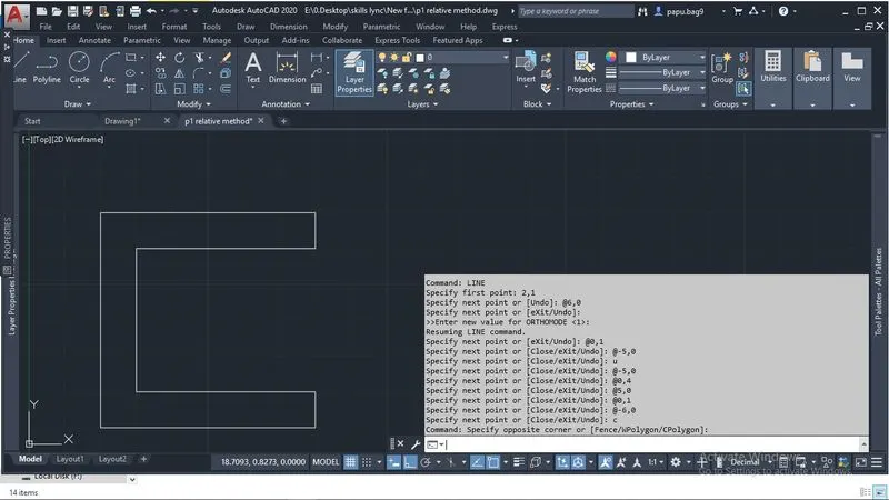
1.3.2 Procedures to draft the picture P1 using relative coordinate system
Choose the line tool (using command L enter)
LINE specify the first point: 2,1
Specify the next point or [Undo]: @ 6,0
Specify the next point or [eXit/ Undo]: @ 0,1
Specify the next point or [Close/ eXit/ Undo]: @ -5,0
Specify the next point or [Close/ eXit/ Undo]: @ 0,4
Specify the next point or [Close/ eXit/ Undo]: @ 5,0
Specify the next point or [Close/ eXit/ Undo]: @ 0,1
Specify the next point or [Close/ eXit/ Undo]: @ -6,0
Specify the next point or [Close/ eXit/ Undo]: C
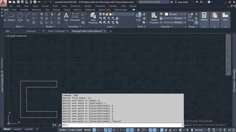
1.3.3 Procedures to draft the picture P1 using direct distance entry coordinate system
Choose the line tool (use command L enter)
LINE specify the first point: 2,1
Specify the next point or [Undo]: 6
Specify the next point or [eXit/ Undo]: 1
Specify the next point or [Close/ eXit/ Undo]: 5
Specify the next point or [Close/ eXit/ Undo]: 4
Specify the next point or [Close/ eXit/ Undo]: 5
Specify the next point or [Close/ eXit/ Undo]: 1
Specify the next point or [Close/ eXit/ Undo]: 6
Specify the next point or [Close/ eXit/ Undo]: C
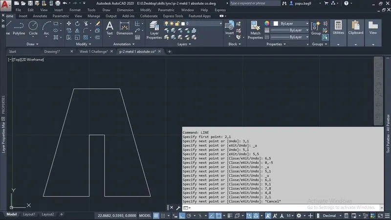
1.3.4 Image with command to draft the picture P2 using absolute coordinate system
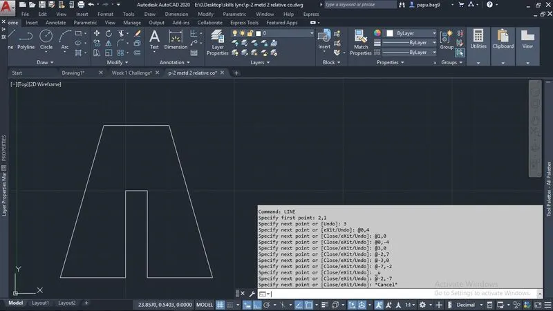
1.3.5 Image with command to draft the picture P2 using relative coordinate system
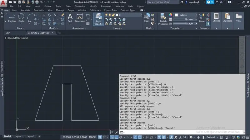
1.3.6 Image with command to draft the picture P2 using direct distance entry coordinate system
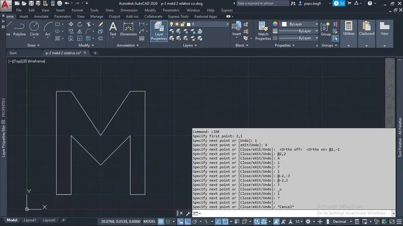
1.4 Procedures to draft image using direct distance entry coordinates methods for P4, P5, P7, P8, P9, P10.
1.4.1 Procedures to draft image using direct distance entry coordinates methods for P4
Choose the line tool (use command L enter)
LINE specify the first point: 2,1
Specify the next point or [Undo]: 1
Specify the next point or [eXit/ Undo]: 4
Specify the next point or [Close/ eXit/ Undo]: @2,2
Specify the next point or [Close/ eXit/ Undo]: 4
Specify the next point or [Close/ eXit/ Undo]: 1
Specify the next point or [Close/ eXit/ Undo]: 7
Specify the next point or [Close/ eXit/ Undo]: 1
Specify the next point or [Close/ eXit/ Undo]: @-2, -3
Specify the next point or [Close/ eXit/ Undo]: @-2, 3
Specify the next point or [Close/ eXit/ Undo]: 7
Specify the next point or [Close/ eXit/ Undo]: 1
Specify the next point or [Close/ eXit/ Undo]: 7
Specify the next point or [Close/ eXit/ Undo]: C
1.4.2 Procedures to draft image using direct distance entry coordinates methods for P5
Choose the line tool (use command L enter)
LINE specify the first point: 2,1
Specify the next point or [Undo]: 1
Specify the next point or [eXit/ Undo]: 7
Specify the next point or [Close/ eXit/ Undo]: 5
Specify the next point or [Close/ eXit/ Undo]: 6
Specify the next point or [Close/ eXit/ Undo]: 3
Specify the next point or [Close/ eXit/ Undo]: 1
Specify the next point or [Close/ eXit/ Undo]: 4
Specify the next point or [Close/ eXit/ Undo]: 8
Specify the next point or [Close/ eXit/ Undo]: 7
Specify the next point or [Close/ eXit/ Undo]: C
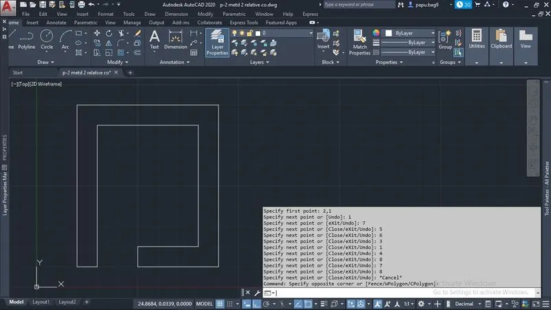
1.4.3 Image with commands to draft image using direct distance entry coordinates methods for P7
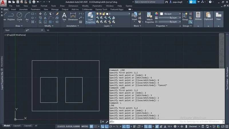
1.4.4 Image with commands to draft image using direct distance entry coordinates methods for P8
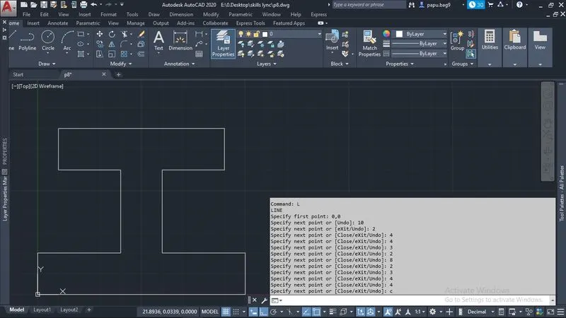
1.4.5 Image with commands to draft image using direct distance entry coordinates methods for P7
1.4.6 Image with commands to draft image using direct distance entry coordinates methods for P10
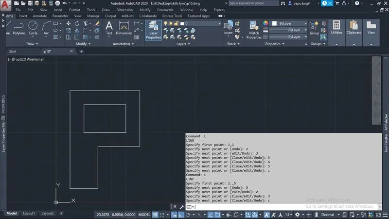
1.5 Procedure to draft the civil related profile and trusses using direct distance entry coordinate methods.
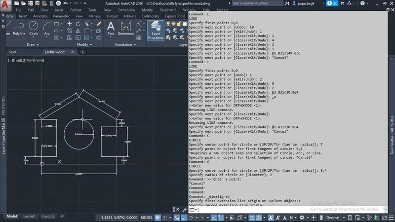
1.5.1 Image and commands to draft the profile-wood using direct distance entry coordinate methods.
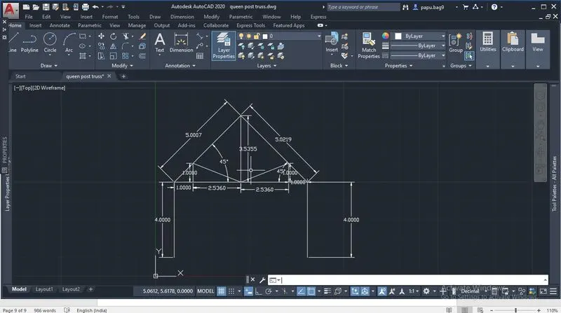
1.5.2 Image and commands to draft the queen-post-truss using direct distance entry coordinate methods.
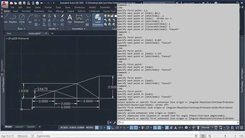
1.5.3 Image and commands to draft the mono-pitch-truss using direct distance entry coordinate methods.
1.6 Results
All the geometries has been drawn using all three coordinates system which has been shown above.