Creating Conceptual mass in REVIT and Creation of Sinusoidal curve and a Parametric stadium using Dynamo
1) Using Dynamo create a set of sinusoidal points and create a curve and create a surface out of the curve.
---------------------------------------------------------------------------------------------------------------------------------------
1.1 Aim of the project- To create a set of sinusoidal points, a curve and surface out of the curve in DYNAMO with relation to REVIT.
1.2 Procedure-
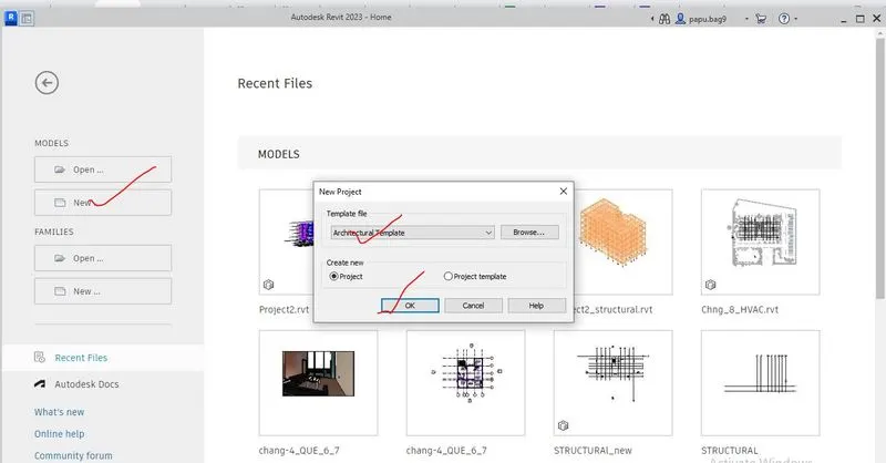
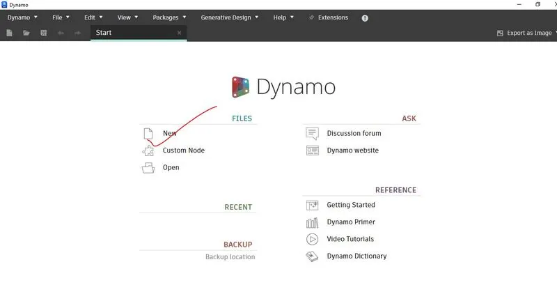
Step-1- First of all, the architectural template has been opened, and then to open the Dynamo, from manage tool the dynamo option has been selected.
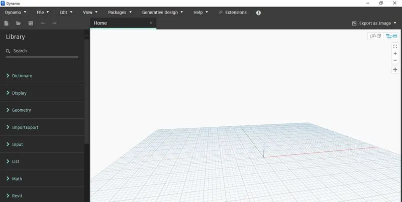
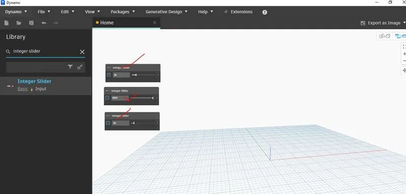
Step-2-After opening of the Dynamo software, by searching the integer slider, three integer slider has been created by coping the one integer slider.
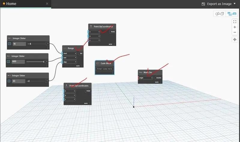
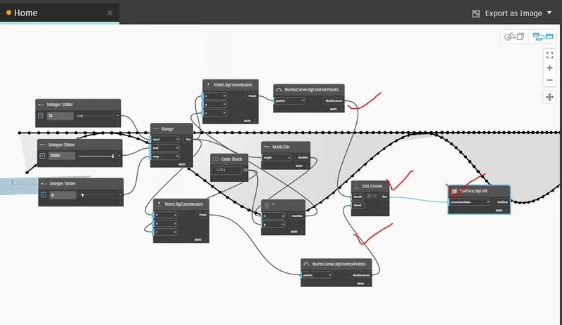
Step-3- Then, range has been created and one slider is connected to start in the range tool, second slider is connected to end and third slider has been connected to step.
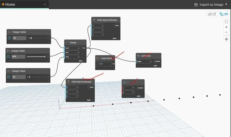
Step-4-After creation of the range, two point by coordinate has been created and a code block has been created and the number 50 has been added to the code block. To add sinusoidal path, a math.sin function in dynamo has been used.
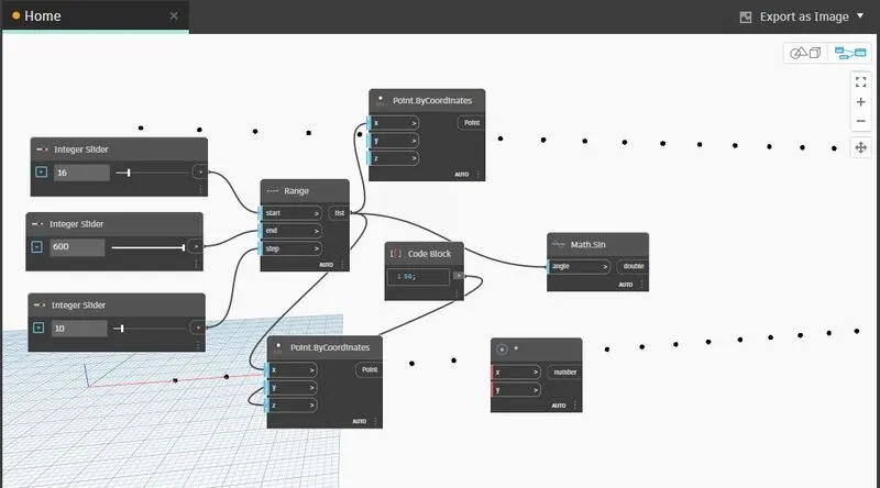
Step-5- Now, connect the range to x coordinate in first point by coordinate, connect range to angle option in math.sin and range to x coordinate in second point by coordinate.
Step-6-Then after constructing a product function which is multiplication code block, the code block is connected to z in second point by coordinate, math.sin has been connected to y in second point by coordinate, math.sin to product x and code block has been connect to product y.
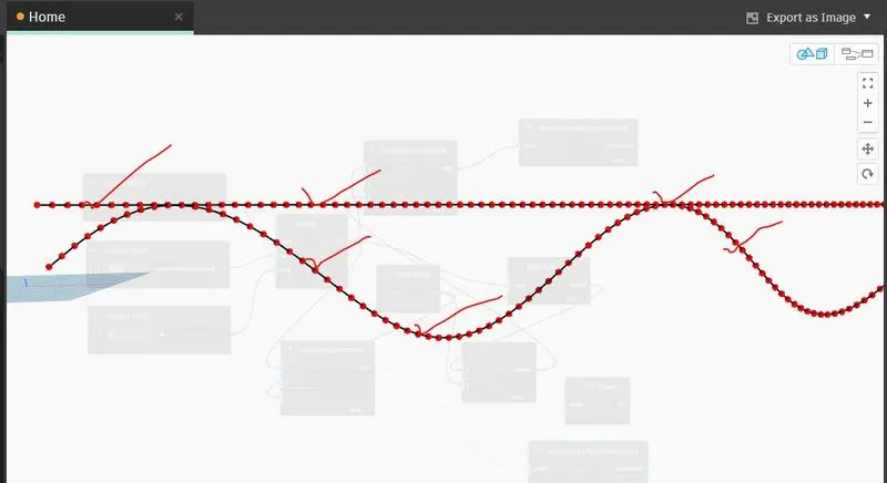
And now the product variant is connected to z in first point by coordinate, up to the sinusoidal point has been created.
Step-7- In order to make to sinusoidal curve, two nurbs by control point has been constructed.
first point by coordinate is connected to points in 1st nurbs by control point and second point by coordinate is connected to the point in 2nd nurbs by control point.
Step-8- A list create has been created and two items has been added as item0 and item 1 in the list create.
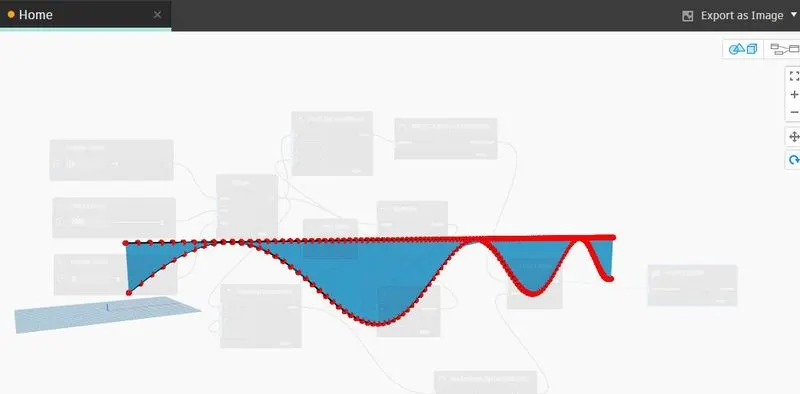
Step-9- Now, the curve has been created by loft option i.e. surface by loft and connect the list to cross-section in surface by loft.
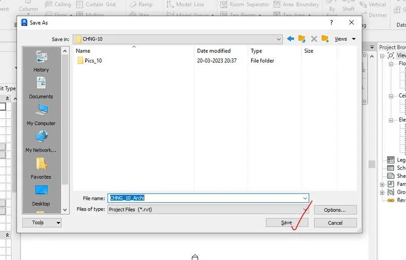
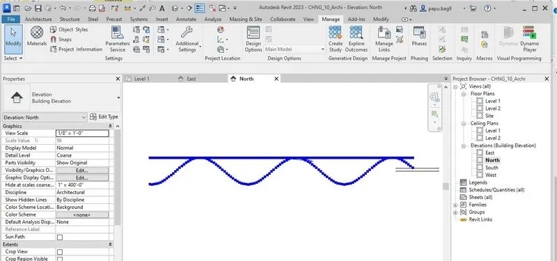
1.2.1 All the step wise screenshots in creating a set of sinusoidal points, a curve and surface out of the curve in DYNAMO is given below,

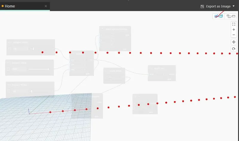
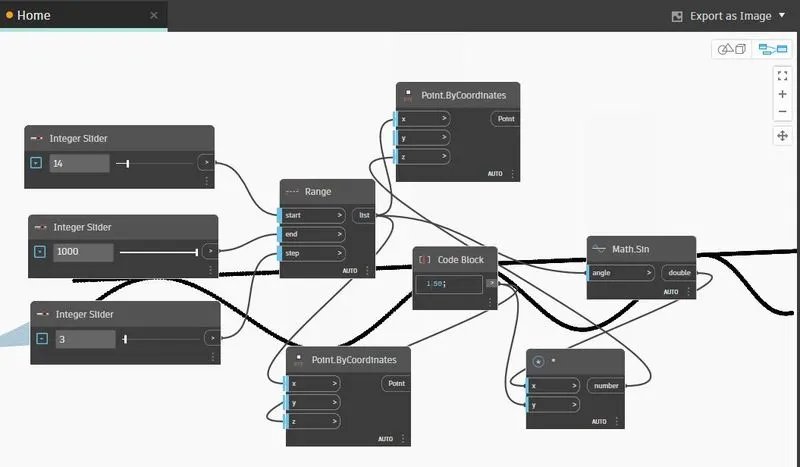
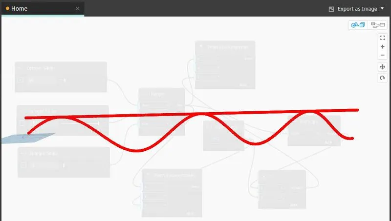
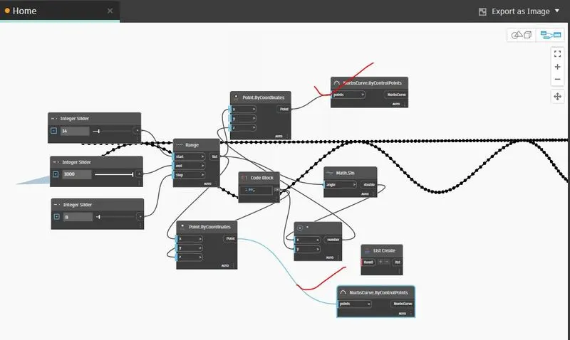
1.3 Results-
The results of creating a set of sinusoidal points, a curve and surface out of the curve in DYNAMO and REVIT i.e. the .rvt file and .dyn is uploaded named as 'CHNG_10_Archi.rvt' and "sinusoidal.dyn" respectively.
-----------------------------------------------------------------------------------------------------------------------------------
2) Create a conceptual layout of floor plan in dynamo . Using the tools available in dynamo link the lines to appropriate model elements in Revit by choosing the wall types and wall parameters. Make use of the sliders to slide through the height of the wall and length of the wall.
-----------------------------------------------------------------------------------------------------------------------------------
2.1 Aim of the project- To create a conceptual layout of floor plan in dynamo and by using the tools available in dynamo link the lines to appropriate model elements in REVIT by choosing the wall types and wall parameters.
2.2 Procedure-
Step-1- First of all, the architectural template has been opened, and then to open the Dynamo, from manage tool the dynamo option has been selected.
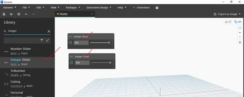
Step-2-After opening of the Dynamo software, by searching the integer slider, three integer slider has been created by coping the one integer slider.
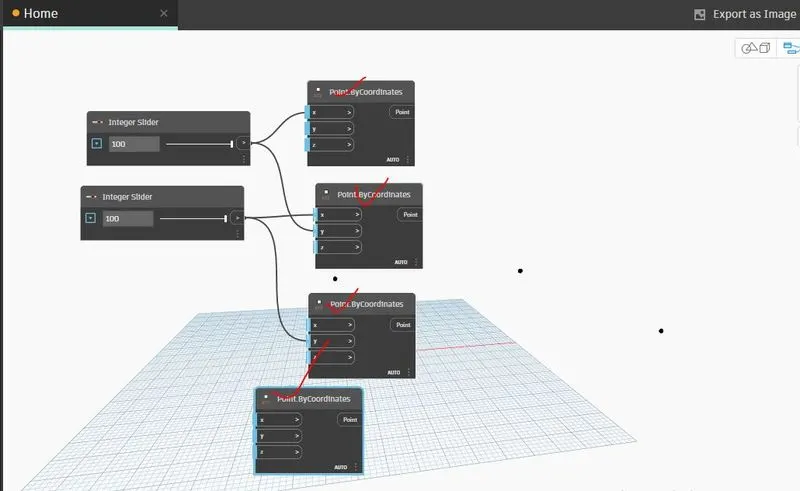
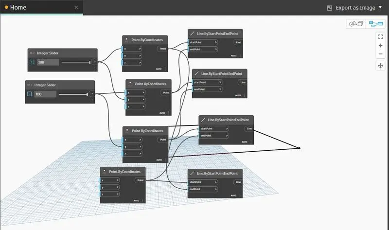
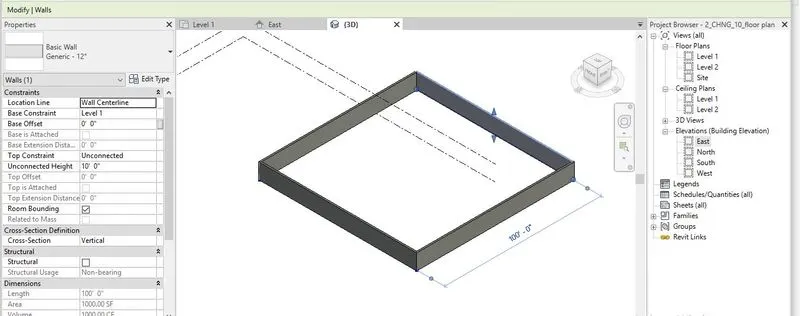
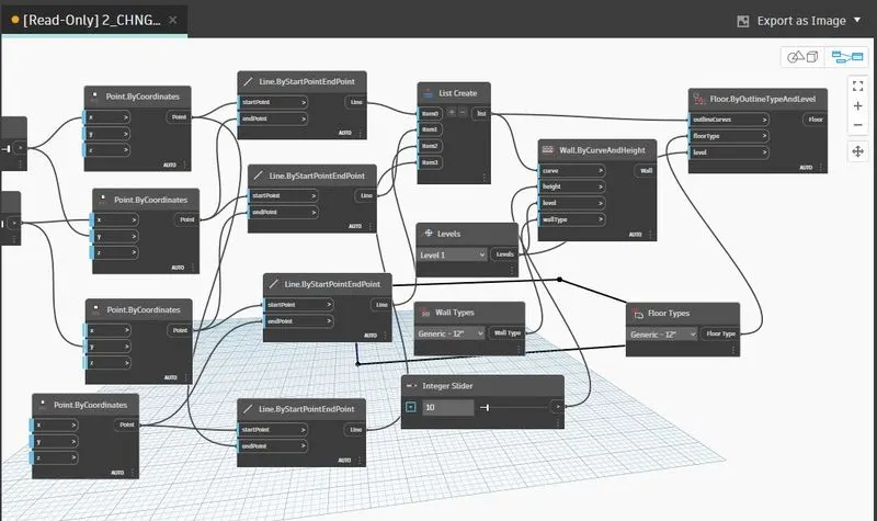
Step-3-For constructing the wall, four point by coordinate tools has been created for four sides of the wall.
Connection
the 1st integer slider to x in 1st point by coordinate,
the 1st integer slider to y in 2nd point by coordinate,
the 2nd integer slider to x in 2nd point by coordinate,
the 2nd integer slider to y in 3rd point by coordinate,
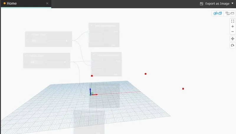
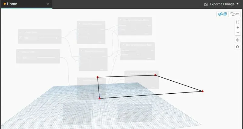
By the above connection, four points has been created.
Step-4- Now, these four points has been connected by four lines i.e. Line by start point end point as four lines is required to join the four points.
Connection
1st point has been connected to 1st line start
2nd point has been connected to 1st line end
1st point has been connected to 4th line end
2nd point has been connected to 2nd line start
3rd point has been connected to 2nd line end
3rd point has been connected to 3rd line start
4th point has been connected to 3rd line end
4th point has been connected to 4th line start
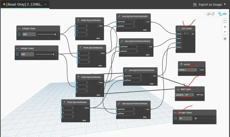
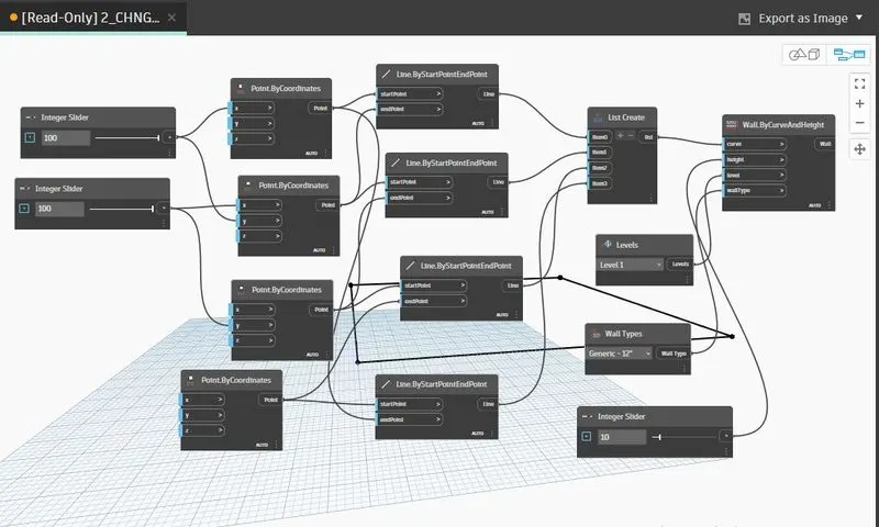
Step-5- To make them 4 set of line to make complete wall, a list create option is required and four items i.e. item0, item1, item2, item3 has been added to list created.
Now connect the 1st line by start point end point to item0, 2nd line by start point end point to item1, 3rd line by start point end point to item2 and 4th line by start point end point to item3.
Step-6- Create a level, wall type, insert one integer slider, wall by curve and height option.
And connect list create to curve, level to level, wall type to wall type and integer slider to height.
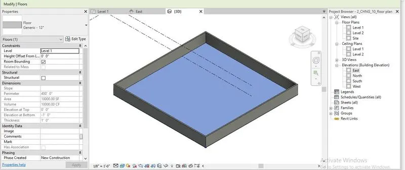
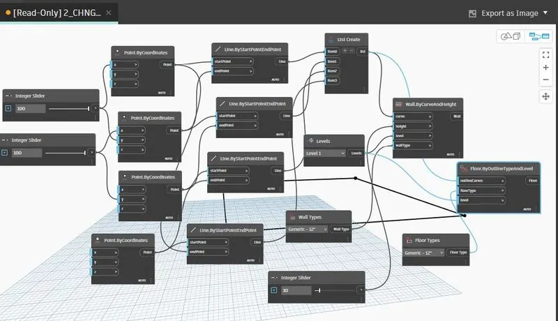
Step-7- In order to create the floor, a floor type and floor by outlined type and level tool has been created.
Step-8- Now connect the list create to outlined curve, floor type to floor type and level to level.
2.2.1 All the step wise screenshots in creating a conceptual layout of floor plan in dynamo and by using the tools available in dynamo link the lines to appropriate model elements in REVIT by choosing the wall types and wall parameters. is given below,

2.3 Results-
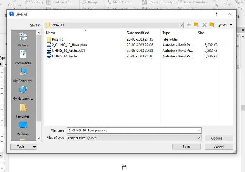
The results of "creating a conceptual layout of floor plan in dynamo and by using the tools available in dynamo link the lines to appropriate model elements in REVIT by choosing the wall types and wall parameters" i.e. the .rvt file and .dyn is uploaded named as '2_CHNG_10_floor plan.rvt' and "2_CHNG_10_floor plan.dyn" respectively.
-----------------------------------------------------------------------------------------------------------------------------------
3) Create an array of model elements in Revit. Use dynamo to vary the properties of model elements by using the slider or code block.
-------------------------------------------------------------------------------------------------------------------------------------------
3.1 Aim of the project- To use dynamo to vary the properties of model elements by using the slider or code block.
3.2 Procedure-
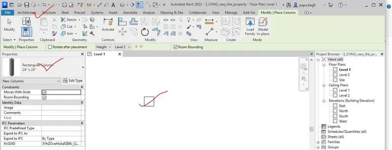
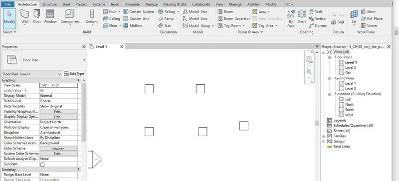
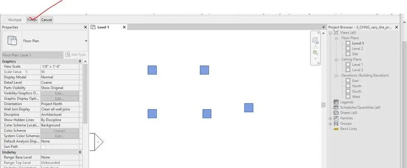
Step-1- First of all, an array of column has been created in the REVIT and then DYNAMO has been opened from the manage tab.
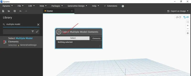
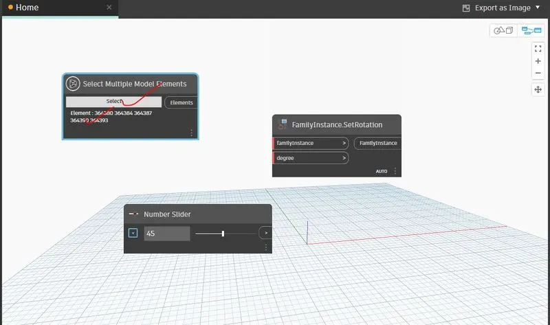
Step-2- After opening of the DYNAMO, a multiple model element has been added to the dynamo and array of column is selected from the REVIT.
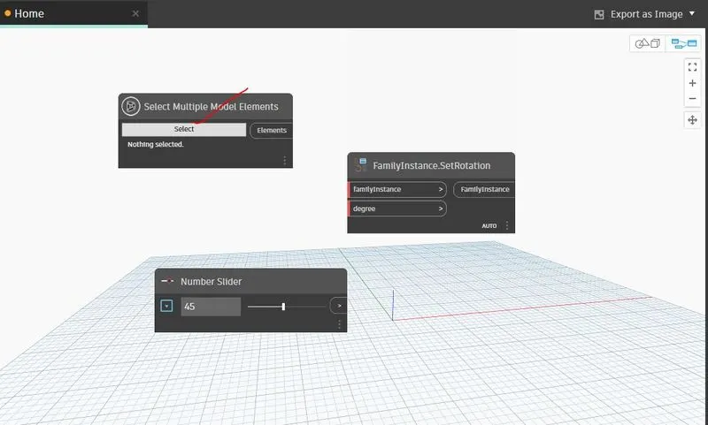
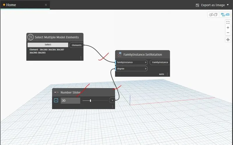
Step-3- A set by rotation option and an integer slider has been added. 30 the number has been set in the integer slider as degree.
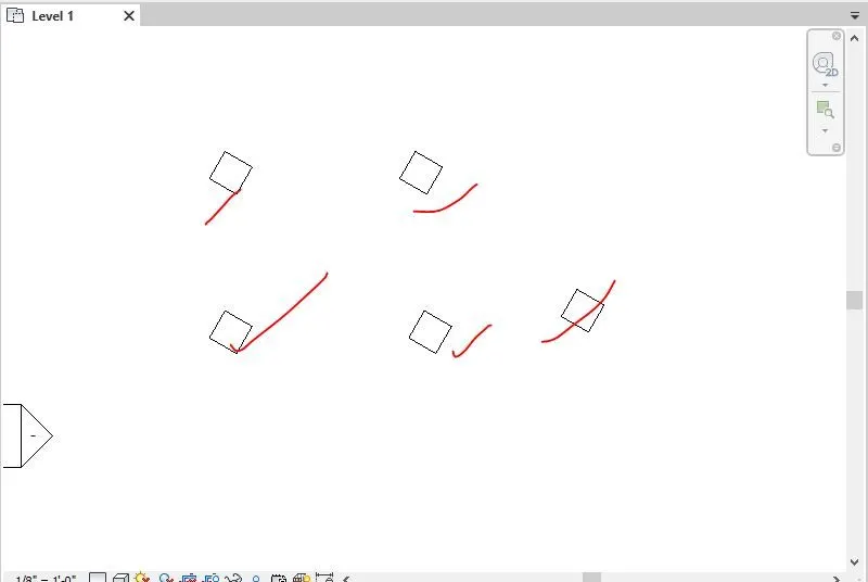
Step-4-Now, the multiple model element is connected to family instance in set rotation and integer slide is connected to degree as 30 degrees.
3.2.1 All the step wise screenshots in using dynamo to vary the properties of model elements by using the slider or code block is given below,
3.3 Results-
The results of "creating a conceptual mass in REVIT and develop a parametric column by dividing the surfaces and apply the concepts similar to use in parametric walkway modelling. To use triangular bent or square shaped panels to add finish to the parametric column" i.e. the .rvt file and .dyn is uploaded named as '3_CHNG_vary_the_property.rvt' and "3_CHNG_vary_the_property.dyn" respectively.
-----------------------------------------------------------------------------------------------------------------------------------
4) Create a conceptual mass in Revit and develop a parametric column by dividing the surfaces and apply the concepts similar to used in parametric walkway modelling. Use triangular bent or square shaped panels to add finish to the parametric column.
-------------------------------------------------------------------------------------------------------------------------------------------
4.1 Aim of the project- To create a conceptual mass in REVIT and develop a parametric column by dividing the surfaces and apply the concepts similar to use in parametric walkway modelling. To use triangular bent or square shaped panels to add finish to the parametric column.
4.2 Procedure-
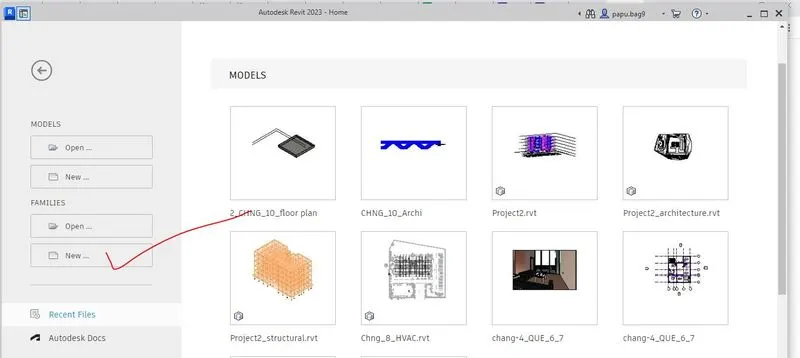
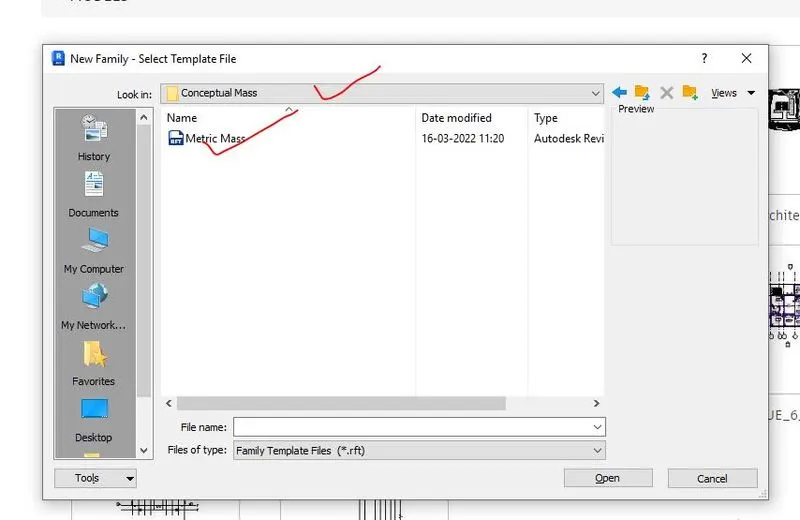
Step-1-After opening the REVIT, by clicking on the new family a conceptual mass has been opened.
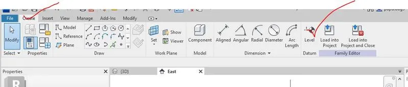
Step-2- By going to elevation view and two more level has been created.
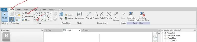
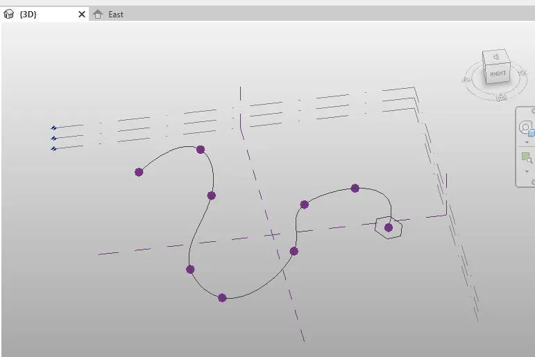
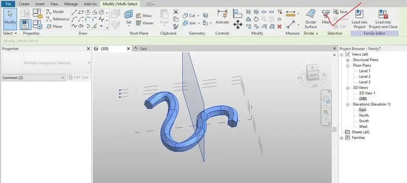
Step-3- A spline of shape S with different level has been created by clicking on model line option from create.
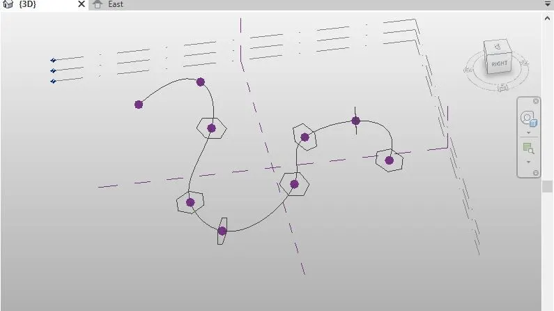
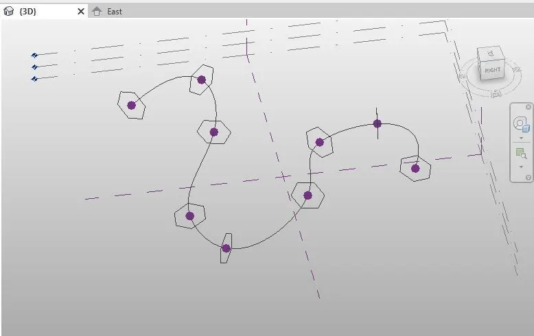
Step-4- Circumscribe polygon has been created by setting the working plane with the height 12’
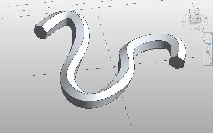
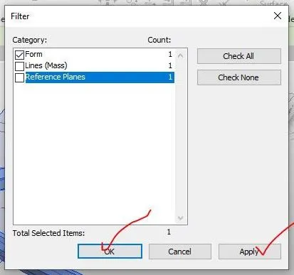
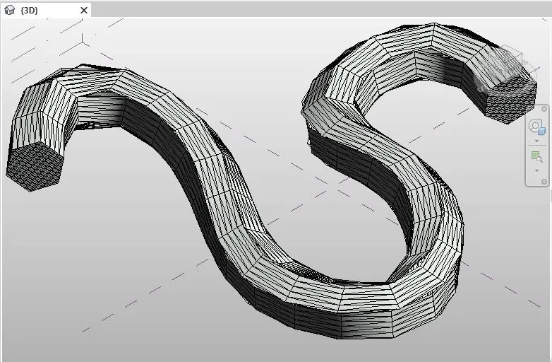
Step-5- Then solid form is created by clicking create form after selection of the object.
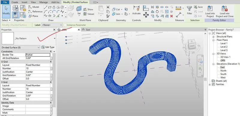
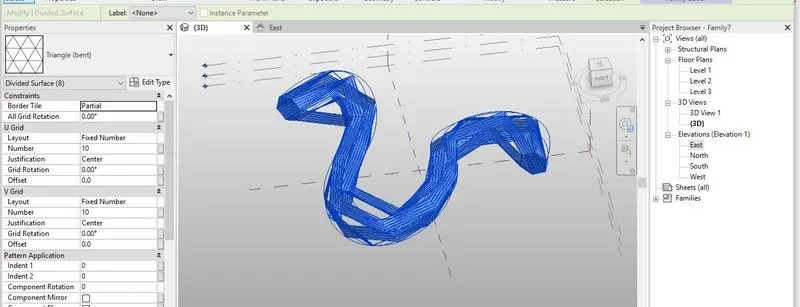
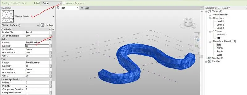
Step-6- To change the pattern, after selection of only form and divide surface option has created. The pattern has been changed from the properties browser.
4.2.1 All the step wise screenshots in creating a conceptual mass in REVIT and develop a parametric column by dividing the surfaces and apply the concepts similar to use in parametric walkway modelling. To use triangular bent or square shaped panels to add finish to the parametric column is given below,


4.3 Results-
The results of "creating a conceptual mass in REVIT and develop a parametric column by dividing the surfaces and apply the concepts similar to use in parametric walkway modelling. use triangular bent or square shaped panels to add finish to the parametric column." i.e. the .rfa file is uploaded named as 'conceptual mass3.rfa'.
----------------------------------------------------------------------------------------------------------------------------------
5) Use Dynamo to work on developing a Parametric Stadium. List your parameters and use the visual programming approach to complete the modelling, You can use the concepts discussed in parametric high rise tower in class for reference.
-------------------------------------------------------------------------------------------------------------------------------------------
5.1 Aim of the project- To work on developing a Parametric Stadium by using DYNAMO, and to List parameters and use the visual programming approach to complete the modelling.
5.2 Procedure-
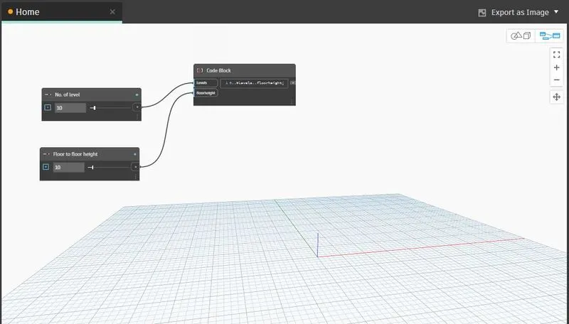
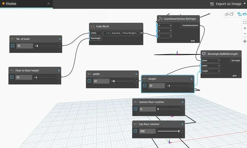
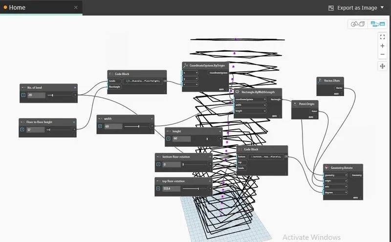
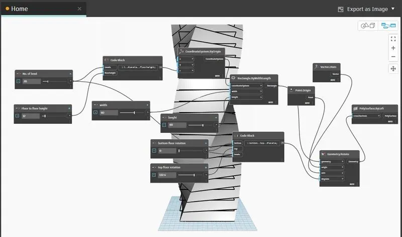
Step-1- Firstly, two integer sliders have been added and named as No of level and floor to floor to height.
Step-2-Then a code block has been added and insert as 0..#levels.. floorheight and connect the level to level in code block and floor to floor height to floorheight.
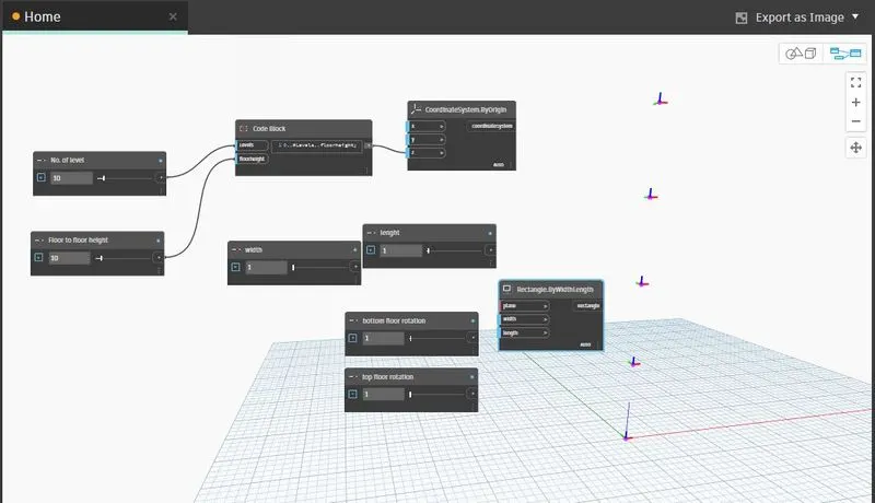
Step-3- Point by coordinate has been created and then code block is connected to y in point by coordinate
Step-4- Then parameters has been created by insertion of integer slider and named as width, length, bottom floor rotation and top floor rotation.
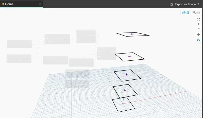
Step-5-To make a rectangular shape structure, a rectangular by width length has been added and then point coordinate is connected to CS in rectangular by width length, width is connected to width and length to length in rectangular by width length,
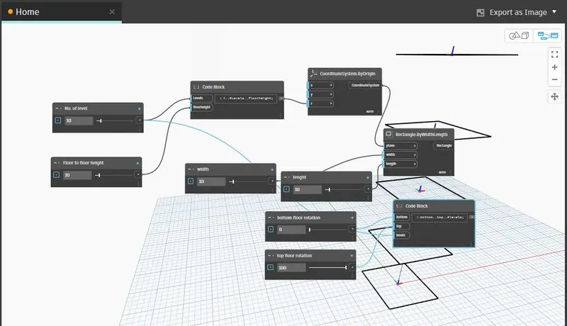
Step-6- Then a code block for floor rotation has been created and coded as bottom..top..#level.
Step-7- Bottom floor rotation is connected bottom and level to level and top floor rotation is connected to top in code block.
Step-8- Construct a create origin, vector in Z axis and geometry rotation (origin, axis, degree).
Connection
Point by coordinate is connected to origin,
Vector in Z axis is connected to axis,
Code block is connected to degree,
Rectangle is connected to geometry.
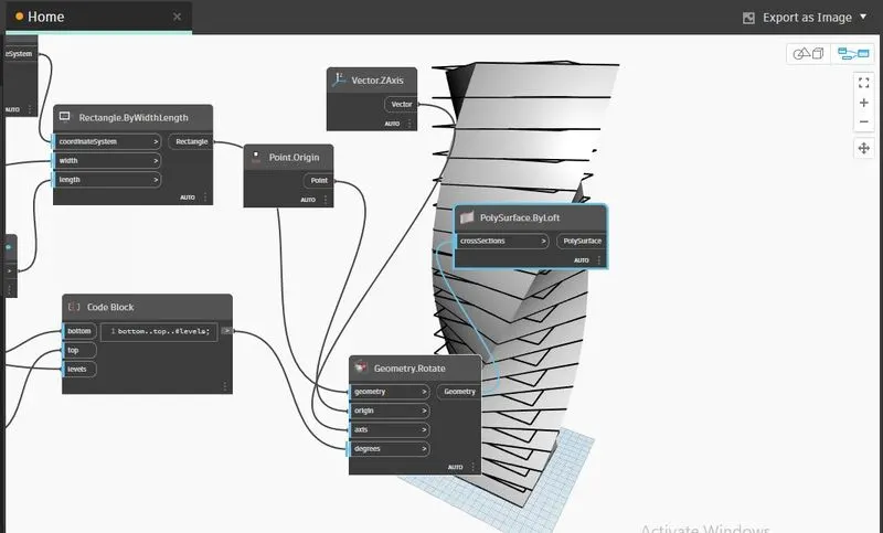
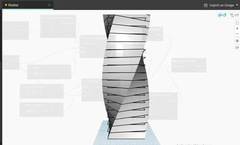
Step-9- To create the surface, polysurface option by loft has been used by connecting geometry to cross-section polysurface.
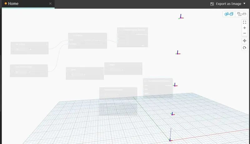
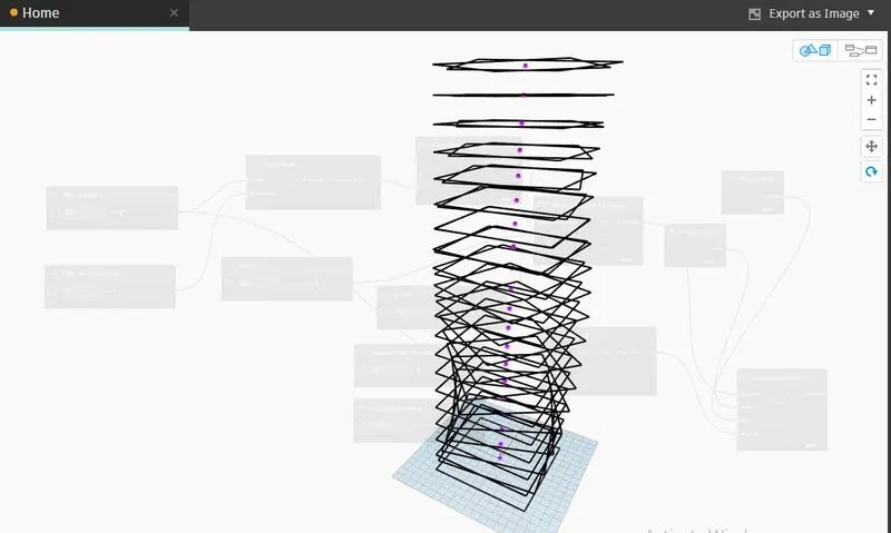
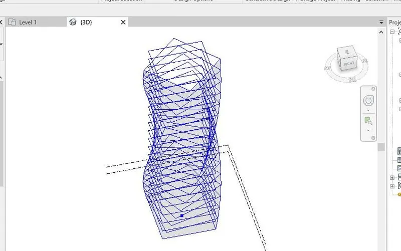
5.2.1 All the step wise screenshots in working on developing a Parametric Stadium by using DYNAMO, and to List parameters and use the visual programming approach to complete the modelling is given below,
5.3 Results-
The results of "working on developing a Parametric Stadium by using DYNAMO, and to List parameters and use the visual programming approach to complete the modelling" i.e. the .rvt file and .dyn is uploaded named as '2_CHNG_10_Parametric.rvt' and "2_CHNG_10_Parametric.dyn" respectively.
-----------------------------------------------------------------------------------------------------------------------------------