Project 1 _Creating an Architectural plan for the provided plot size and develop relevant basic structural drawings
- Aim and introduction
1.1 Aim of the challenge: -Creating an Architectural plan i.e. floor plan, elevation and sectional view with staircases for the plot size 18.3m ×6m and develop relevant basic structural drawingse. column layout, beam layout and footing layout.
1.2 Introduction: - In the architectural plan, there are some objects like external wall, internal wall, window, stairs, doors, cup-boards and rooms for example bed room, toilets, dining and living rooms has to show with required size and dimension and structural drawing shows the column, beam layout and footing layout in which the details of the location of the all the beams and columns with their sizes and the footing location also.
1.2.1 Information for the architectural plan and structural drawing,
- Here the size of the plot size is 18.3m ×6m.
- Facing of the building is east facing.
- Size of the doors are 2000mm × 650mm, 2000mm × 800mm and 2000mm ×720mm.
- Size of the windows are 1200mm×1000mm
- Sill height of the building is 800mm,
- Lintel height of the building is 2000mm,
- Size of the external wall is 230mm and internal wall of size 150mm,
- No of columns are 17,
- No of beams are 23.
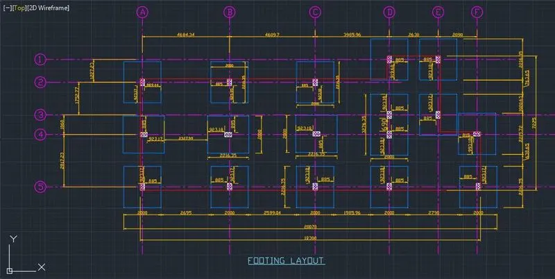
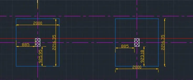
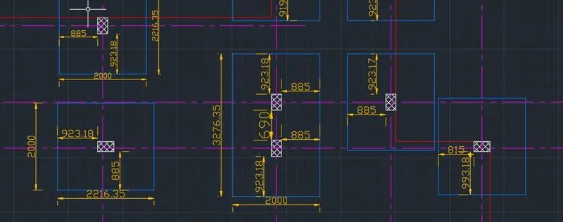
- Footing sizes are 35×2000 and 2000 ×2216.35.
1.2.2 Commands used in above residential plan
- ‘UN’ for units
- ‘LIMITS’ for specify the limit of the sheet.
- ‘L’ (for line)
- ‘PL’ (for poly line)
- ‘O’ for offset
- ‘LA’ for layer
- ‘LAYON’ AND LAYOFF’ layer on and off.
- ‘MI’ for mirroring the object
- ‘RO” for rotating the object
- “CO” for copy
- “XL” for construction line
- ‘TR’ for trimming the object
- ‘F’ for filleting
- ‘C’ for circle
- ‘ARC’ for arch of circle
- ‘REC’ to draw rectangle
- ‘J’ to join
- ‘DIM ‘for dimension, DIMLIN (for linear dimension), DIMBREAK, DIMCONTINUE, DIMBASE
- ‘DDIM’ for dimension style manager
- MT for multi text
- ‘ED’ (for edit text)
- ‘B’ (for creation of the block)
- ‘I” (for insertion of the block)
- ‘SC’ (to scale the objects)
- ‘H’ (for hatching)
1.3 Procedures to Sketch the Architectural Drawing of a residence building.
1.3.1 Procedure to sketch the floor plan of the residential building
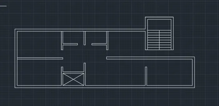
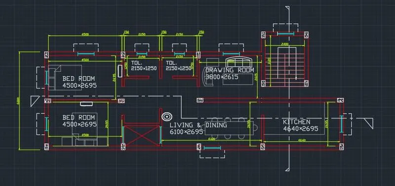
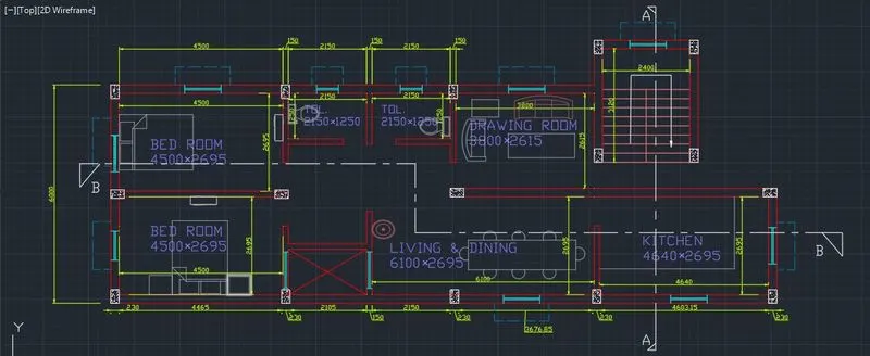
- After starting the AUTOCAD, the unit and limits should be specified. As per our requirement, the unit has been taken in Engineering and, metric unit. So to select unit, UN command is used to select the units as engineering and the angle as decimal degrees and limits has been specified as <0,0> to <60000,66000>.
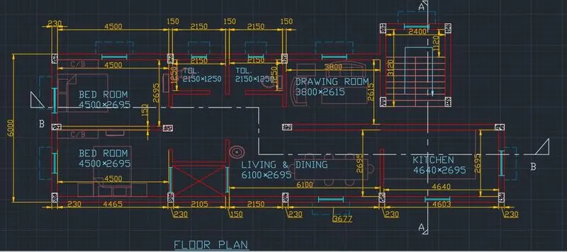
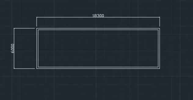
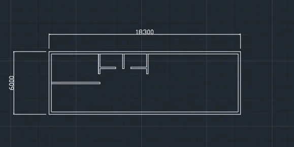
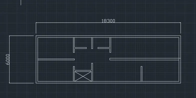
- Now by using the line command or also by using the XL command i.e. construction line the plot area of 18300 mm *6000mm. And the with help of offset command the wall of size 230mm and internal wall of 150mm. Then clear space of the room is constructed by using the trim tools.
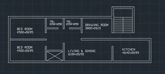
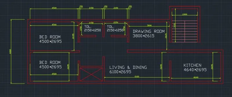
- Two bed rooms of size 4500×2695, two toilets of size 2150×1250, kitchen of 4640×2695, drawing room of 3800×2615, living room of size 6100×2695, all the dimension is mentioned with the help of DIMLINEAR tools.
- Next to draw the stair cases of tread of size of 250mm with the help of the offset tools and by using the leader tool, the direction of the steps i.e. UP in stairs is showed.
- By using the circle, rectangle and line command, the door and window is done.
- After completion of all the necessary item like walls, doors and windows and staircase, to demonstrate or to mention the type of rooms like bed rooms, kitchen, toilets, living room and drawing room, the MT command is used to mention the name of the rooms with their sizes.
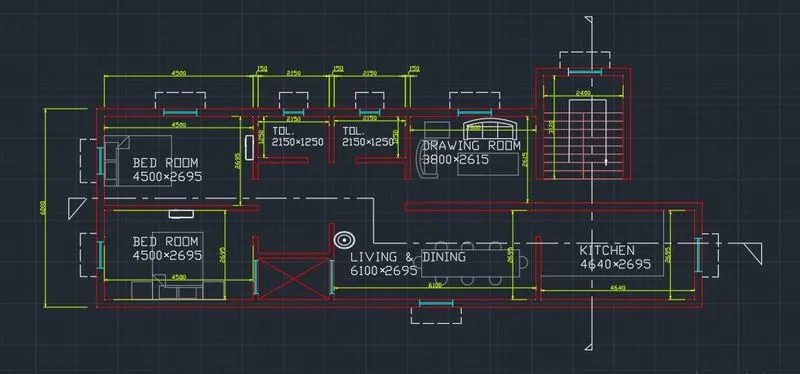
- Next to draw the furniture, the block tool is used to draw all the necessary block and with the help of the I command i.e. insertion of the blocks as per our requirement blocks have been inserted and scale to their required size. And also with the help of design centre some of them are inserted.
- Next the section line with the centre line style has been drawn and the chhaza also with dash line.
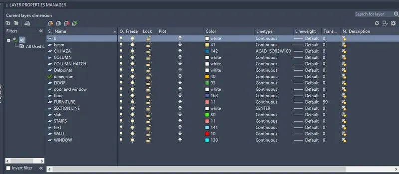
- To specified or to differentiate the all the item, different layer is made with different colours.
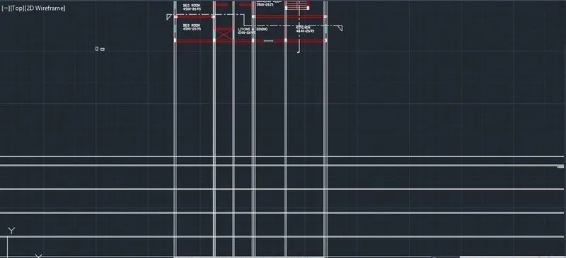
1.3.1.1 Stepwise screen shots in drafing of the floor plan is given below,
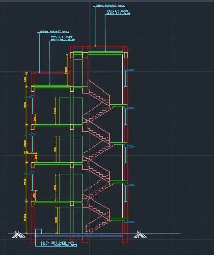
1.3.2 Procedure to sketch the elevation of the section A-A of the residential building
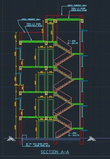
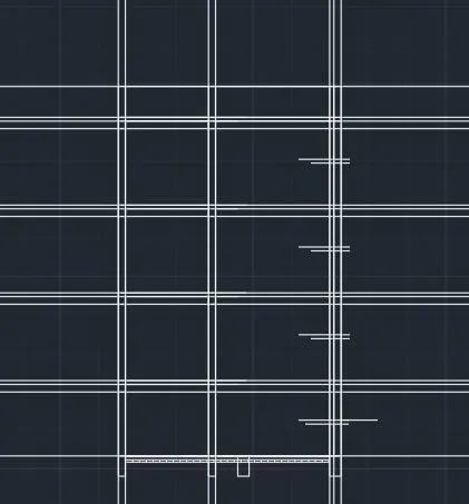
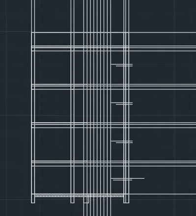
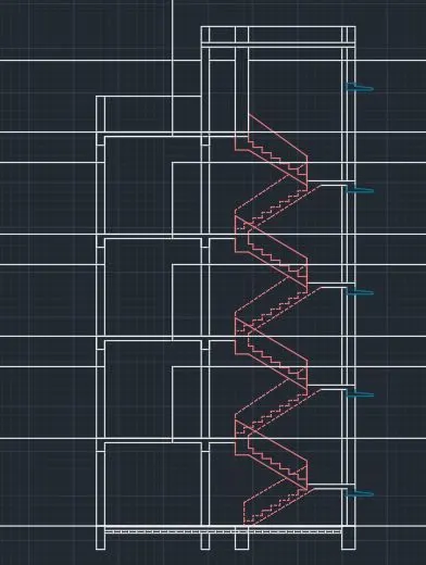
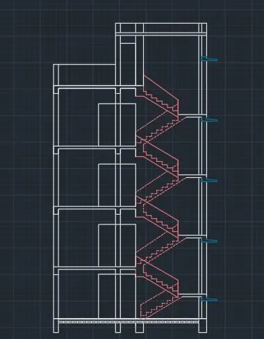
- As per the section, we need to rotate the section for better construction of view.
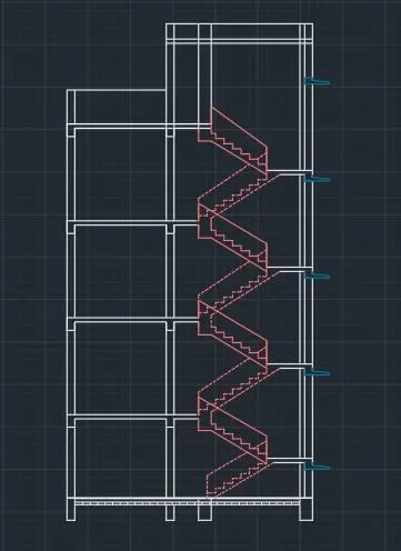
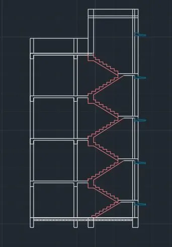
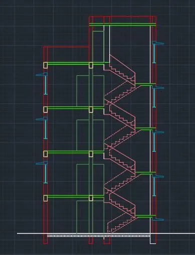
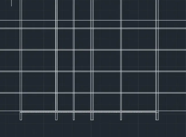
- Now, with the help of XL command, at the required section, the wall, the doors, windows, chhaza, and staircases is mentioned.
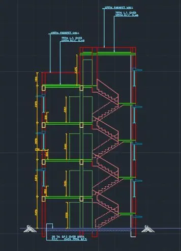
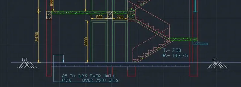
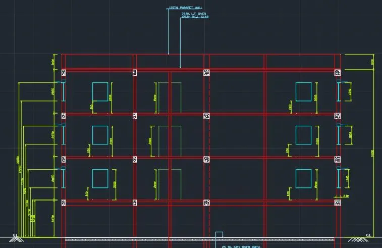
- Ground level with 25mm thickness of the DPC and 75 mm thickness of BFS and 100mm thickness of PCC of drafted with the help of offset i.e. offsets of 25mm, 75mm and 100mm respectively.
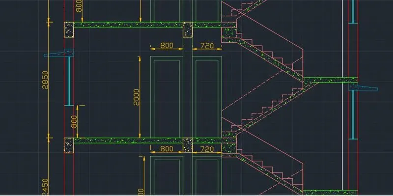
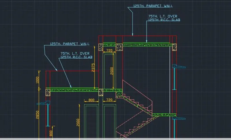
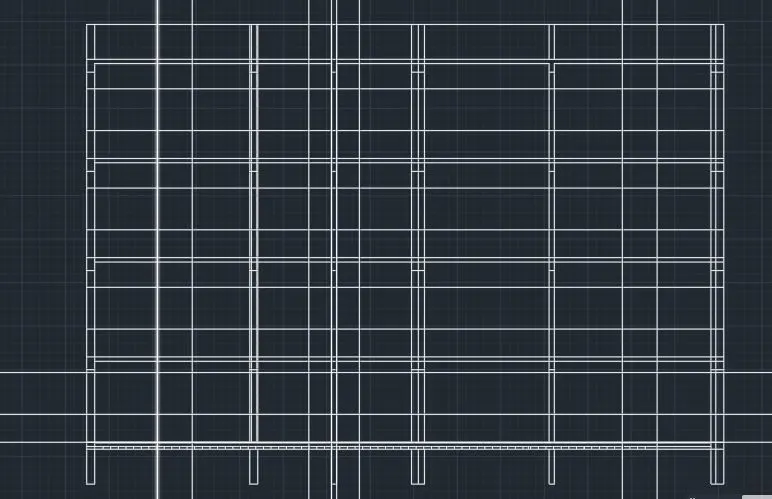
- Now the height of the floors of 4 stories is drawn with the help of offsets command i.e. the offsets of 2450mm and 2850mm of other story heights and parapet wall of 1000mm height and mumty of height 2375mm.
- Lintel level at 2000mm and sill level at 800mm is drawn again with the help of offsets i.e. O enter.
- Door size of 2000 × 800 and 2000 ×720 has been drawn by using the line and offset command.
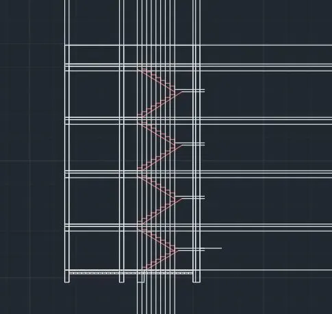
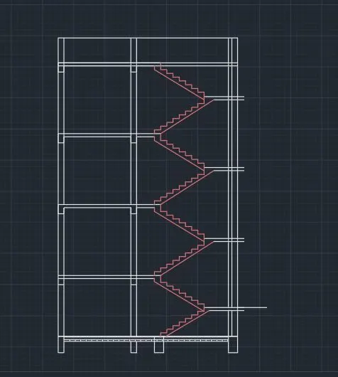
- The treads and riser in the staircases is drawn with the construction line and offsets command with respect to or with referring the floor plan at required section. i.e. tread of size 250mm and rise with 143.75mm and 151.39mm.
- After completion of all the necessary items, to specified or to differentiate the all the item, different layer is made with different colours.
- To show the size of all the important items, the DIMLIN, DIMCONTENUE, DIMBASE is used to demonstrate the all the dimension.
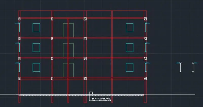
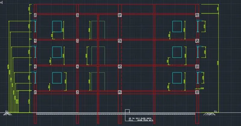
1.3.2.1 Stepwise screen shots in drafing of the elevation for the section AA is given below,
1.3.3 Procedure to sketch the elevation of the section B-B of the residential building
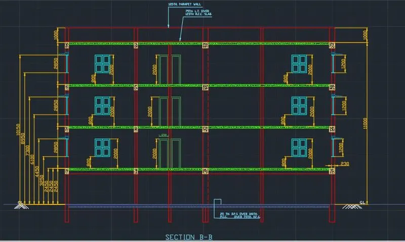
- As per the section required, with the help of XL command, the wall, the doors, windows, chhaza is mentioned and the construction lines is drawn.
- Ground level with 25mm thickness of the DPC and 75 mm thickness of BFS and 100mm thickness of PCC of drafted with the help of offset i.e. offsets of 25mm, 75mm and 100mm respectively.
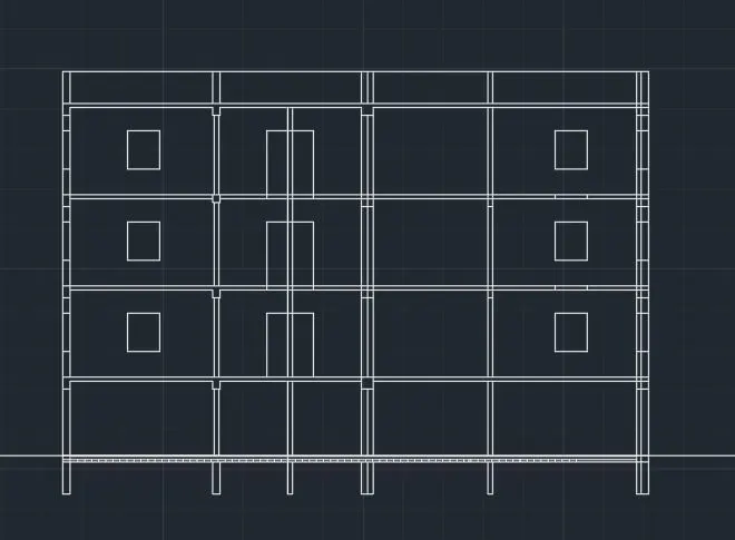
- Now the height of the floors of 4 stories is drawn with the help of offsets command i.e. the offsets of 2450mm and 2850mm of other story heights and parapet wall of 1000mm height
- Lintel level at 2000mm and sill level at 800mm is drawn again with the help of offsets i.e. O enter.
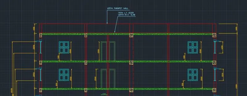
- Door size of 2000 × 650 and window size of 1200×1000 have been drawn by using the line and offset command.
- After completion of all the necessary items, to specified or to differentiate the all the item, different layer is made with different colours.
- To show the size of all the important items, the DIMLIN, DIMCONTENUE, DIMBASE is used to demonstrate the all the dimension.
1.3.3.1 Stepwise screen shots in drafing of the elevation for the section BB is given below,
1.4 Procedures to Sketch the structural drawing of a residence building
1.4.1 Procedures to Sketch the beam layout of a residence building
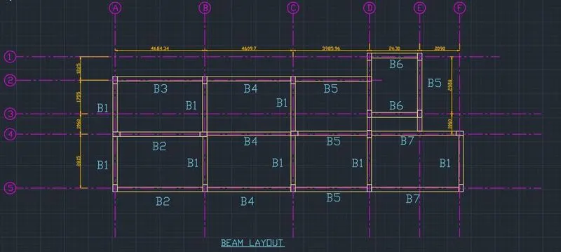
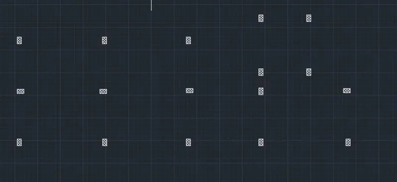
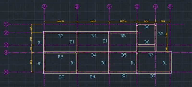
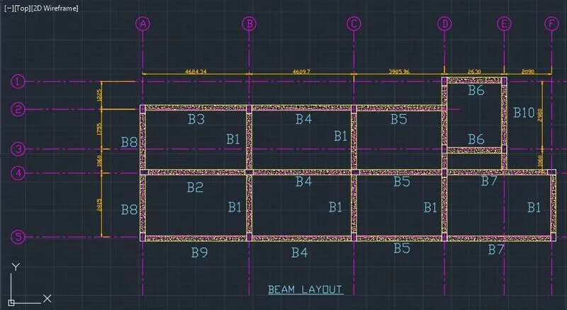
- In order to draw the beams at the required places. Firstly, all the columns should be arranged with respect to their concerned places which can be determine by doing the all the layers except the column layer.
- Then by using the copy tool, the column layout can be found.
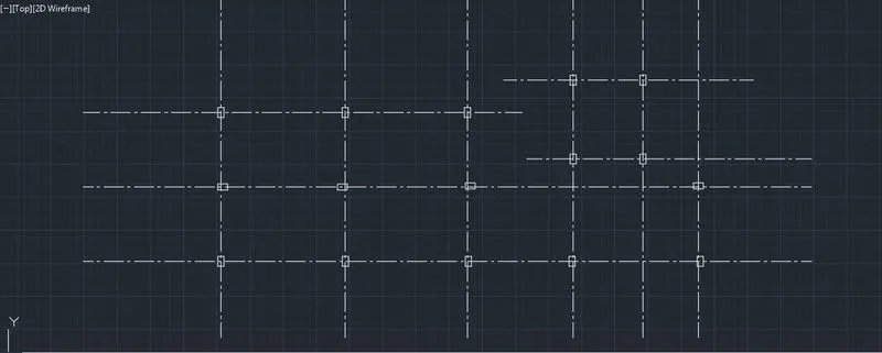
- Now, according to their centre points of all the columns, the central lines connecting all the columns is drawn by using the construction line with changing the line type to central line type.
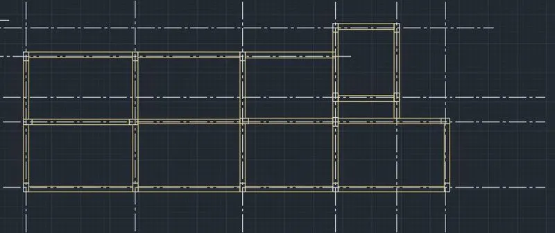
- Next to draw the beam with their respective sizes as per size in floor plan that has been drawn early.
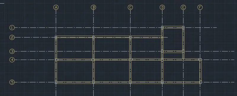
- Next to mention the name of the beams like B1, B2, B3, B4, B5, B6, B7, B8, B9, B10 by using the DT command or text command as given in the screen shots of the drawing.
- Then the spacing of the beams is shown by using the dimension tool.
- Hatching tool has been used to mention the material type i.e. concrete is used.
1.4.1.1 Stepwise screen shots in drafing of the beam layout is given below,
1.4.2 Procedures to Sketch the columns layout of a residence building
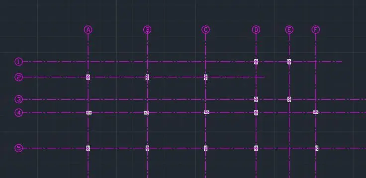
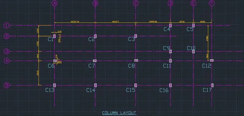
- Firstly, all the columns should be arranged with respect to their concerned places which can be determine by doing the all the layers except the column layer.
- Then by using the copy tool, the column layout can be found.
- Now, according to their centre points of all the columns, the central lines connecting all the columns is drawn by using the construction line with changing the line type to central line type.
- Next to mention the name of the beams like C1, C 2, C3, C4, C5, C6, C7, C8, C9, C 10,C11, C12, C13, C14, C15, C16 AND C17 by using the DT command or text command as given in the screen shots of the drawing.
- Then the spacing of the columns is shown by using the dimension tool.
- Hatching tool has been used to mention the material type i.e. concrete is used.
1.4.2.1 Stepwise screen shots in drafing of the column layout is given below,
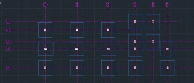
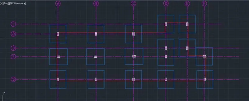
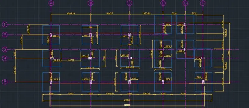
1.4.3 Procedures to Sketch the footing layout of a residence building
- Firstly, all the columns should be arranged with respect to their concerned places which can be determine by doing the all the layers except the column layer.
- Then by using the copy tool, the column layout can be found.
- Now, according to their centre points of all the columns, the central lines connecting all the columns is drawn by using the construction line with changing the line type to central line type.
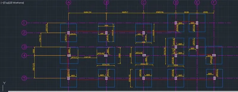
- Footing size of 2216.35×2000 and 2000 ×2216.35 which is rectangular in shape, so the footing of respective size has been drawn by using the rectangular tool.
- By using the copy tool, the rectangular footing has been copied to their respective places.
- Next to mention the dimension of the spacing of the footing and size of the footing, the dimension tool has been used to mention the dimension and size of the footing.
1.4.3.1 Stepwise screen shots in drafing of the beam layout is given below,
1.5 Results:-
All the diagrams of the floor plan, elevation, sectional views, beam layout, coloum layout, footind layout and layers is given below and dwg file named "projects-1,,Architectural plan for the provided plot size an basic structural drawings.dwg" and "Creating an Architectural plan for the provided plot size and develop relevant basic structural drawings.dwg" has been uploaded.