Creating Architectural and Structural model with 3D rendering using REVIT
1) Select the type of structure you want to build from one of the three below:
a. Multi-Unit Residential Apartment
b. Office Buildings
c. School
Ans- From the above option, I want to select the type of structure u.e. Multi-Unit residential apartment.
2) Assume reasonable assumptions for geographic and location details for your project modeling. Based on assumptions and type of structure selected identify the modeling requirements from NBC.
ANS.- Reasonable assumption for the geographical and location details for the project modelling of Multi-unit residential apartment,
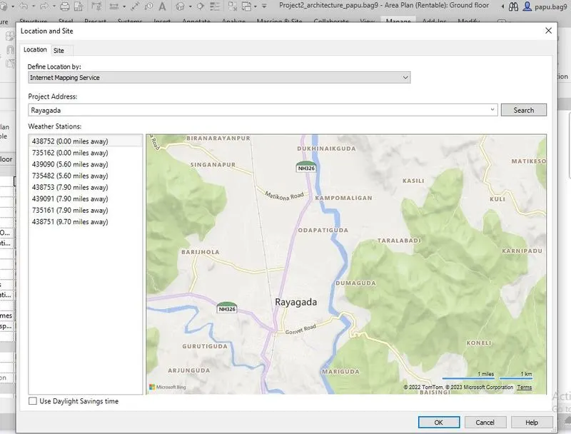
- Geographical location: Rayagada, Odisha.
- Project information of Multi-unit apartment,
- Project name- Alpha apartment
- Client name- Alpha
- Building name- Alpha apartment
- Organisation name- Prem
- Author- Skill_lync
- Project Issue date-29-02-2023
- Project number-1
- Apartment having plot area of 9025 Sq-Feet and floor area of first floor is 2741 Sq-Feet which is same floor area of second, third and floor plan and it has G+4 storey with total height of 60 feets (18.38 meter) and floor height of 12 feets.
- As per clause 8.2.1.1, page 23, Minimum Front open space around the building is 4.5 m for the width of street fronting the plot 18m to 30m. Here the front open space has been taken as 17.54 feet (5m) which is more than 4.5m, hence it is ok as per NBC.
- The type of construction as type 2 construction, as per the Table no-3 page-27, the FAR value for the residential building shall be taken as 2.0.
Note- Floor area Ratio= (Total floor area in all the floor)/(plot area)= (5*2741 Sq-Feet)/( 9025 Sq-Feet)= 1.518 which is less than 2.o, as per NBC, it is ok.
1.Height Restriction
As per NBC, Part-3, clause C-9.41, page no-26,
The maximum height= 1.5 *(Width of road abutting + front open space).
Note-
Here in this project, height of the building is equal to 60 feet (18.38m), width of road abutting 9m, then maximum height of the building = 1.5 *(9+7) = 24m that means, the height of the apartment is satisfy the NBC.
For this model, the height of the building is 27’ (= 8.2296m) which is less than 15m i.e. ok for the height of the building.
2.Room sizing
From NBC, part-3, clause C-2.3, page no-43 and 44
Habitable room-
In a house a two rooms, first room shall not less than 9.0 sq-m with minimum width of 2.5m and the second room shall not be less than 6.5 sq-m with minimum width of 2.1m provided that the total area of both rooms is not less than 15.5 sq-m.
Note-
In this project, Bed room 1 has 17.0013 Sq-m (183 Sq-feet) which is more than 9.0 sq-m and the bed room 2 has 15.423 Sq-m (163 Sq-feet) which is more than 9.0 sq-m and total area of both the room is more than 15.5 sq-m.
Water closet/ bathroom
- The size of independent water closet shall be 0.90 sq-m with minimum width of 0.9m.
- The size of independent bathroom shall be 1.20 sq-m with minimum width of 1m.
- The size of combined bathroom and water closet shall be 1.80 sq-m with minimum width of 1m.
Note –
In this project, the combined bathroom has a size of 7.246 Sq-m (78 Sq-feet) which is more than 1.80 Sq-m. Hence is satisfied the NBC.
Kitchen
- The size of a cooking alcove serving as cooking space shall not be less than 2.4 sq-m with minimum width of 1.2m.
- The size of individual kitchen provided in a two roomed house shall not less than 3.3 sq-m with minimum width of 1.5m.
Note –
In this project, the size of a cooking alcove serving as cooking space has 8.732 Sq-m (94 Sq-m) which is more than 2.4 Sq-m, hence it is satisfied by the NBC.
Balcony
- The minimum width of individual balcony, where provided, shall be 0.9m, and shall not be more than 1.2m and it shall not beyond the plot line and on roadway or pathway.
Basement
- No basement floor shall be allowed.
-------------------------------------------------------------------------------------------------------------------------------------
3) Using the structural model, include the following components based on the type of structure selected
a. Foundation – Isolated / Wall/Matt Foundation
b. Columns
c. Beams Connected to Columns
d. Roof Framing/ Truss
e. Floor / Decks
f. Floor Openings for Elevators and Stairs
--------------------------------------------------------------------------------------------------------------------
3.1 Aim of the Project- To include the structural components like foundation, columns, beam connected to columns, roof framing, floor and floor openings for elevators and stairs by using the structural template in REVIT for structural design purpose and for BIM.
3.2 Introduction- As per previously planned architectural model with proper grids in longitudinal and transvers directions, the structural component like foundation, columns, beam connected to columns, roof framing, floor and floor openings for elevators and stairs has been add to the structural model in structural template for the design purpose with the help of specifying the same coordinate of the plan in architectural as well as structural plan and also by using the copy monitor tools.
3.2.1 Tools used in this structural model
- Structural template
- Grid
- Level
- Specify coordinate
- acquire cordinate
- Project Base point
- Collaborate
- Copy monitor tools
- Link REVIT
3.3 Procedure
Step 1- Drafting of the floor plan on the plot area with proper dimension by using the architectural template.
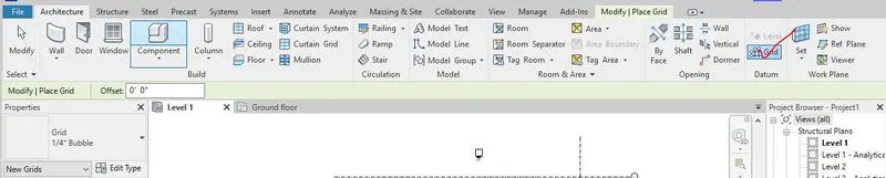
Step 2- Making the levels and the grid as per the location of the columns i.e. the selection of the both longitudinal and the transvers grids in such way that the intersection of the both grids should possess the respective columns.
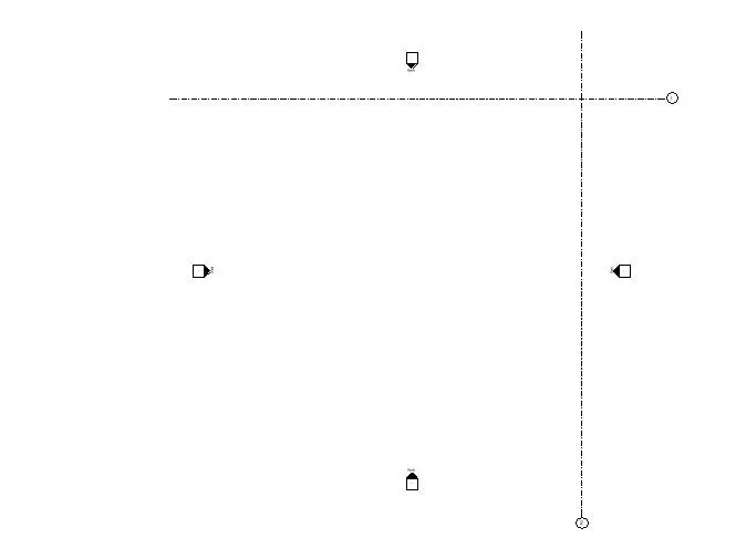
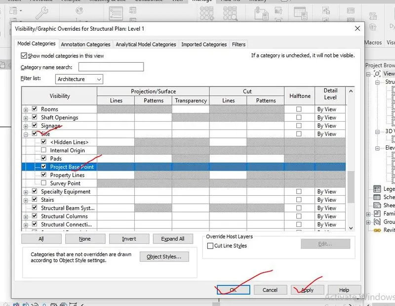
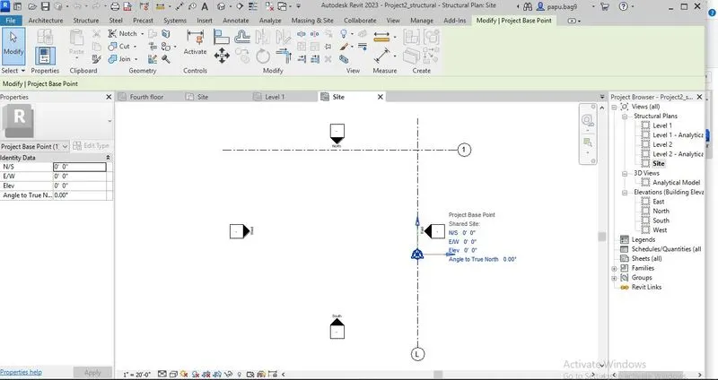
Step 3- Adjusting coordinates of both the grids by specifying the coordinate by using the manage tool, so that we can find the location of base point and the grid location. Selection of the base point and specifying the coordinate of grids could make the grids on sync in the structural template.
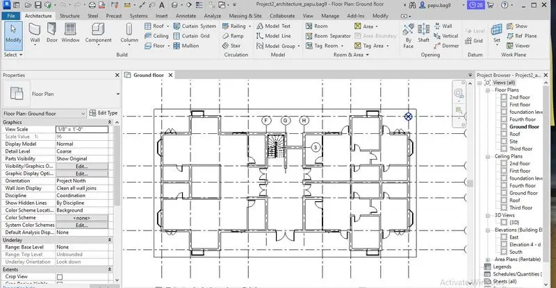
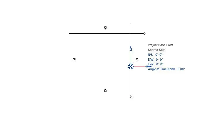
(Layout of the Floor plan with grids and project base points)
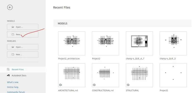
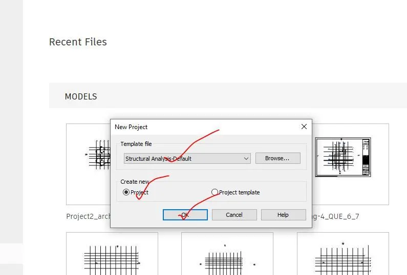
Step-4- After completion of floor plan with proper grids and levels in the architectural template, the next step to open the structural template, where an arbitrarily one transvers and one longitudinal has been drown, after drawing of the arbitrarily grids, the intersection point has been chosen as base point and the coordinates of the base point is changed as the coordinate on architectural base point.
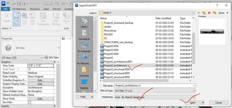
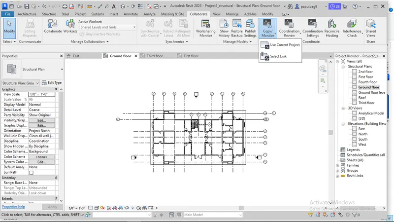
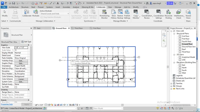
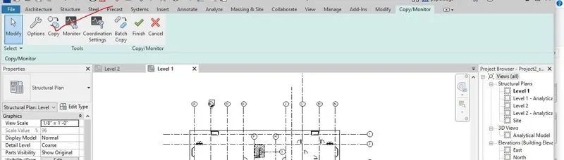
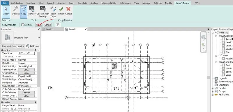
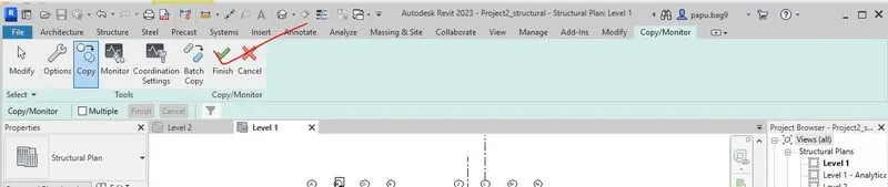
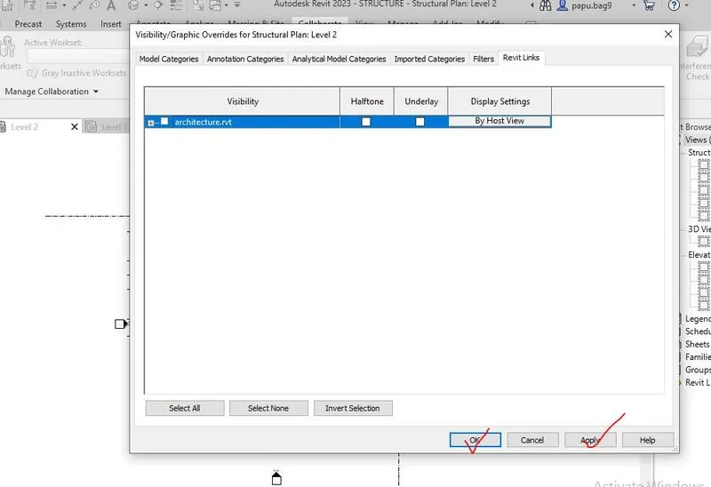
Step-5- After making the base point coordinate same as architectural base point, the architectural floor plan has been inserted by using the Revit link from insert tool which is opened with Auto by shared coordinate where the all the required data like grids and level has been copied by using the copy monitor tool from collaborate tool.
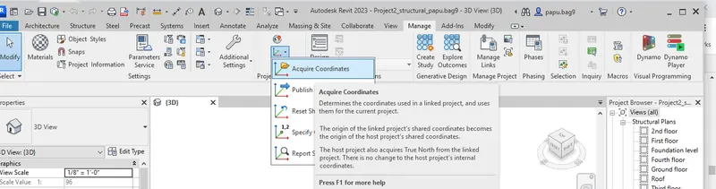
Step-6- The next step is to acquire the coordinate by using the acquire ordinate from manage tool and by relocate the project, the grids of the structural template have been synchronised.
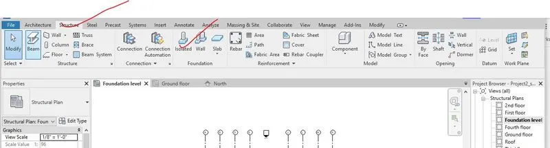
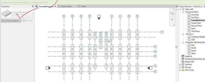
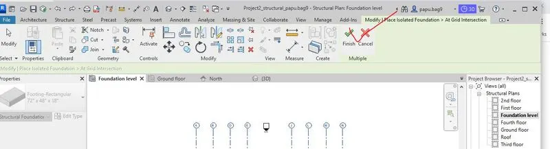
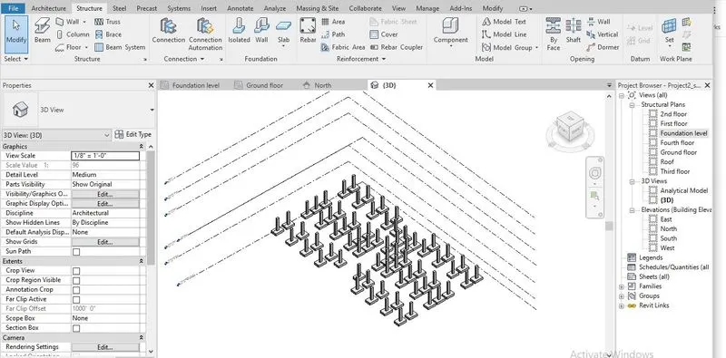
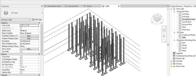
Step 7- After setting out all the grids and level, the isolated footings have been added to the foundation level by selecting the isolated footing from structure tool and with the help of at grids tools, the footings have been assign to all the intersection of the grids. The screen shots in drafting of footings is shown in below.
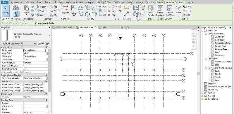
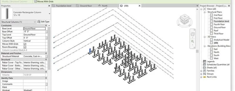
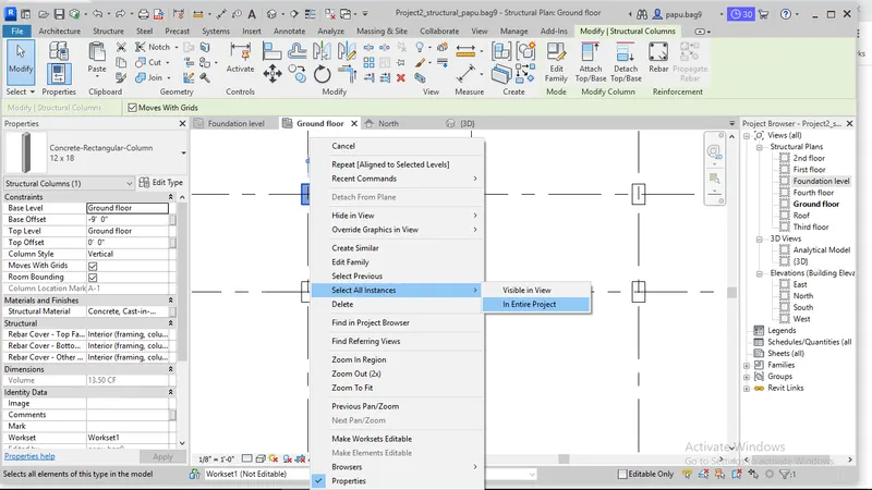
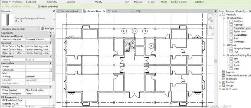
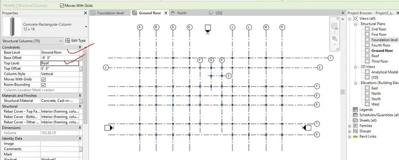
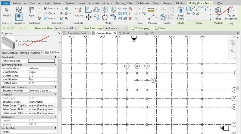
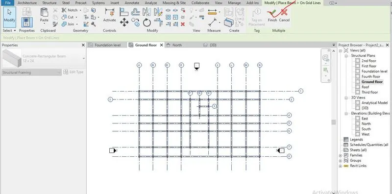
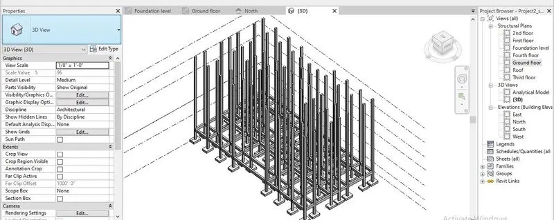
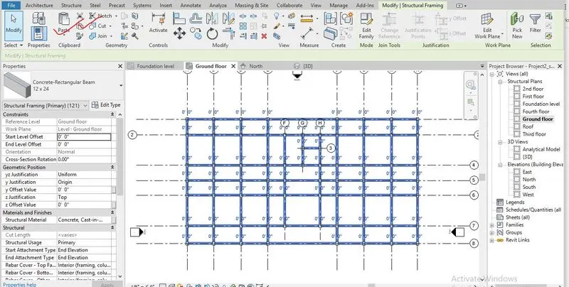
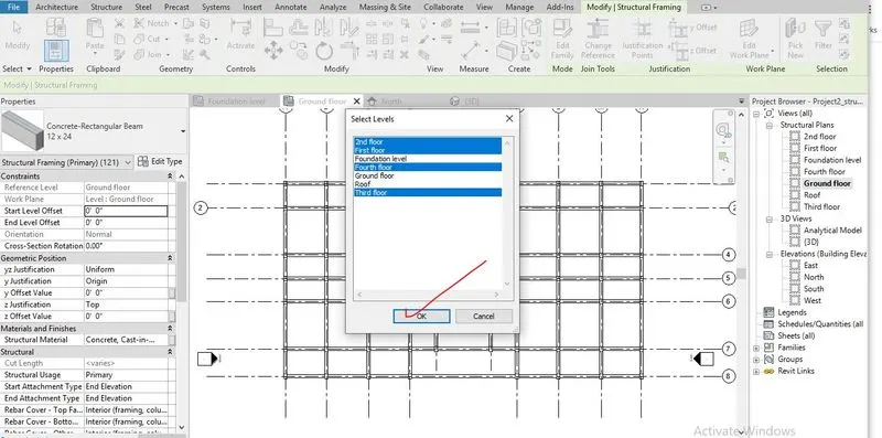
Step-8- Similarly, the beams and columns has added to the structural template by using the column and beam tool from structure tab and it has been to proper place by using at grid tools.
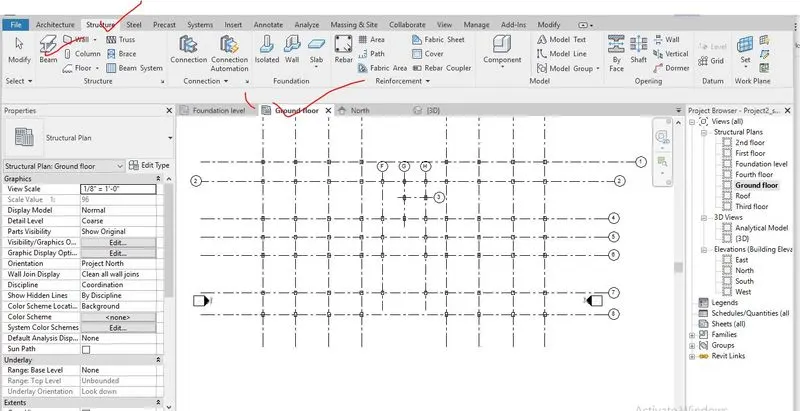
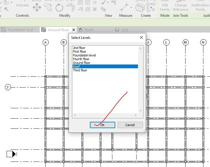
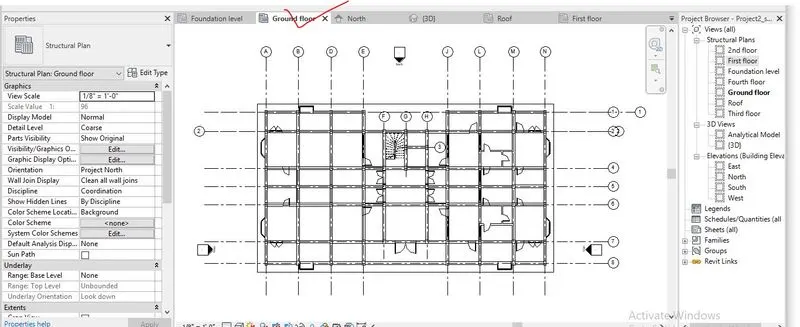
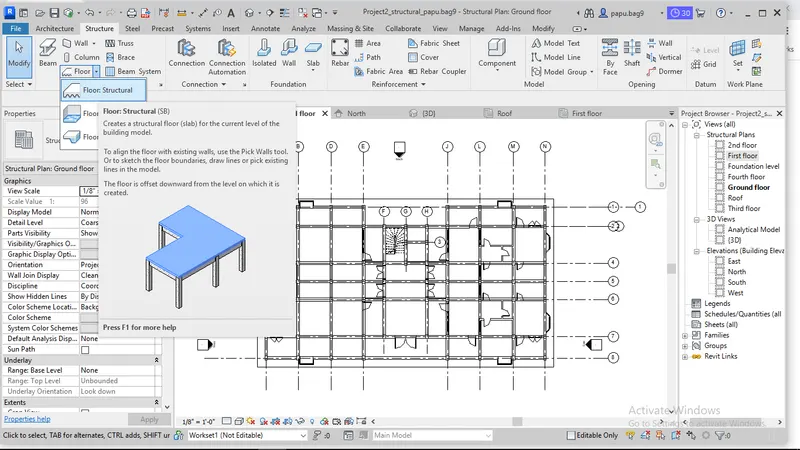
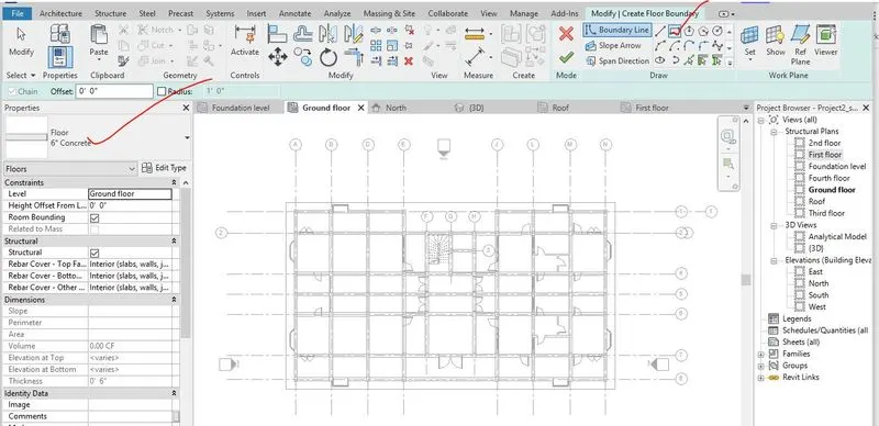
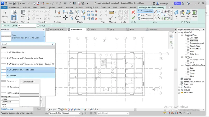
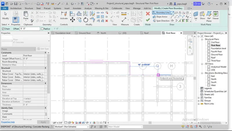
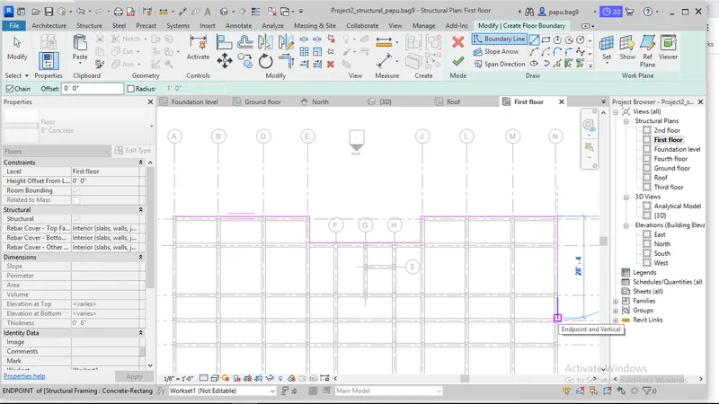
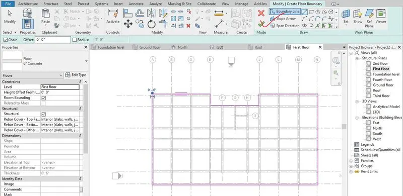
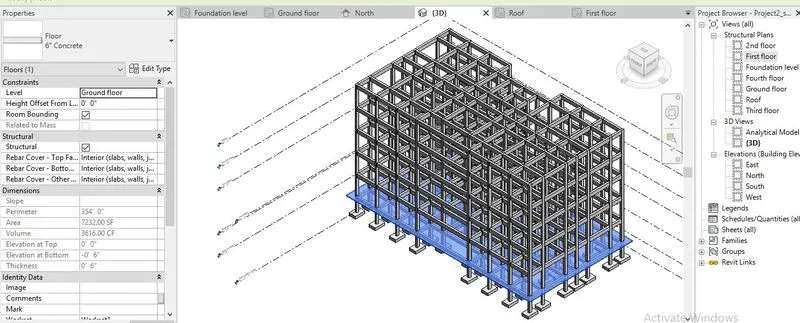
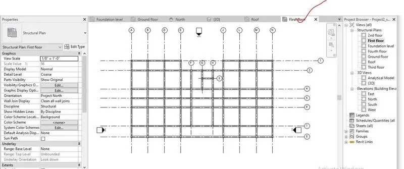
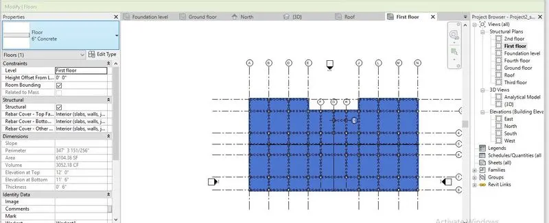
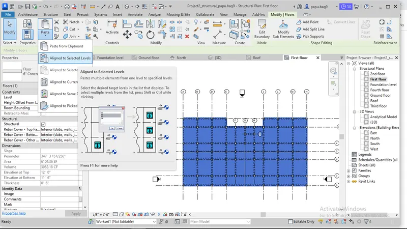
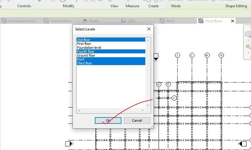
Step-9- The next step is to add the slab in all the floor, first in the ground floor the slab has been created and the according to the different floor plan the slab has been added to respective floor, here in this project by using the rectangle tool the slab has created in every floor and with the help copy and paste in the selected level. All the screen shots in making the slab in every floor has been shown below.
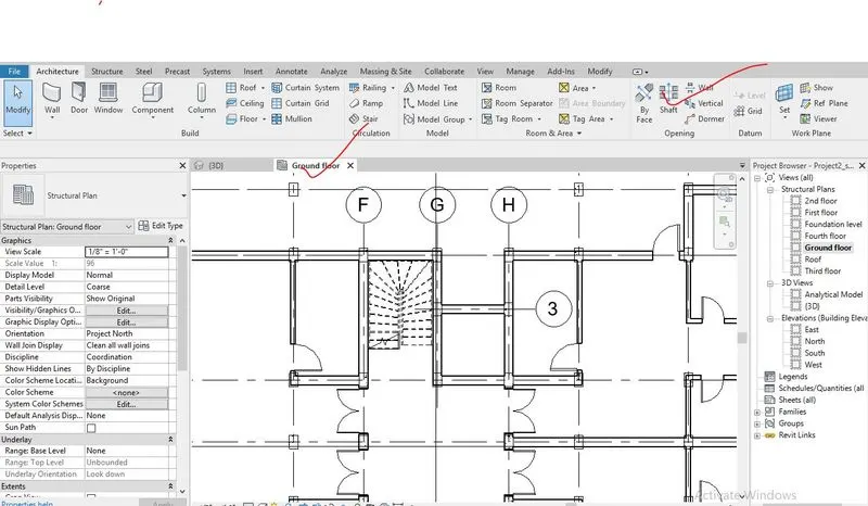
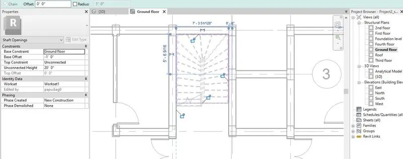
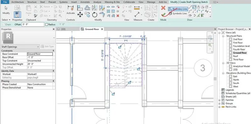
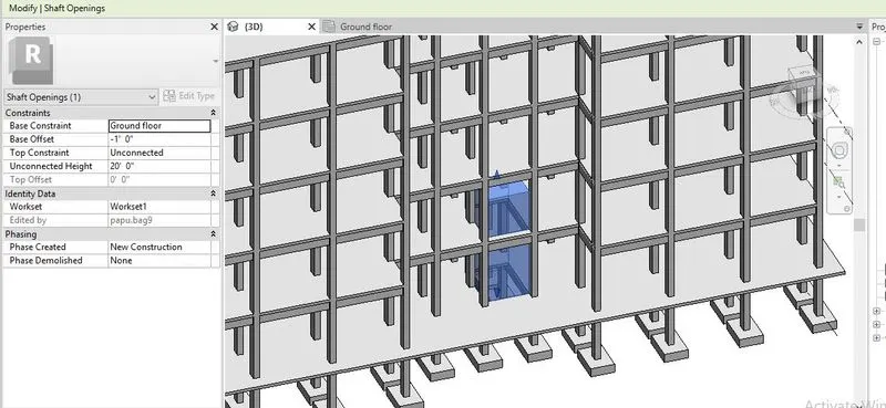
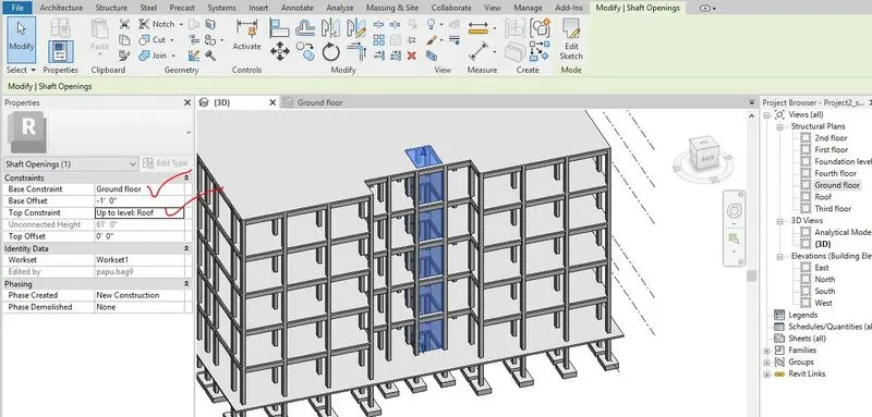
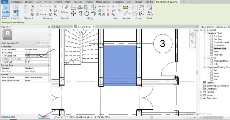
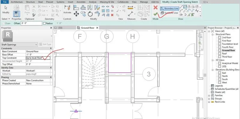
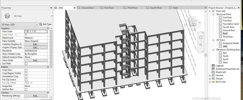
Step-10- With the help of shat tools, the open space for stairs and elevator according to the floor plan, has been created in the respective location.
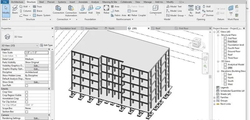
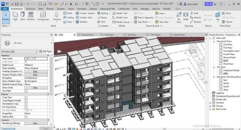
All the Screen shots in modelling the structural components has been shown below,








3.4 Results
- The results of including the structural components like foundation, columns, beam connected to columns, roof framing, floor and floor openings for elevators and stairs by using the structural template in REVIT i.e. the .rvt file is uploaded named as 'Project2_structural'.
----------------------------------------------------------------------------------------------------------------------------------------------------------------------------------
4) Using the architectural model, include the following components based on the type of structure selected
a. Wall Layout with appropriate material and finishing
b. Exterior façade with fancy finish
c. Interior partition walls to size rooms
d. Components to add details to a room ( Desk, Chair, Lighting, Plumbing fixtures)
e. Add components such as stairs Elevators
f. Have at-least one side of the building with curtain walls and glass panels
g. Include interior and exterior lighting fixtures
h. Place proper topographic components from outside ( Trees, Parking, Plants) to add details to the model.
----------------------------------------------------------------------------------------------------------------------------
4.1 Aim of the project- To include the Architectural components like Wall Layout with appropriate material and finishing, Exterior façade with fancy finish, Interior partition walls to size rooms, Components to add details to a room (Desk, Chair, Lighting, plumbing fixtures), stairs Elevators, one side of the building with curtain walls and glass panel, interior and exterior lighting fixtures and topographic components from outside (Trees, Parking, Plants) to add details to the model which is based on structural component by using the Architectural template in REVIT for structural design purpose and for BIM.
4.2 Procedure in drafting the architectural model
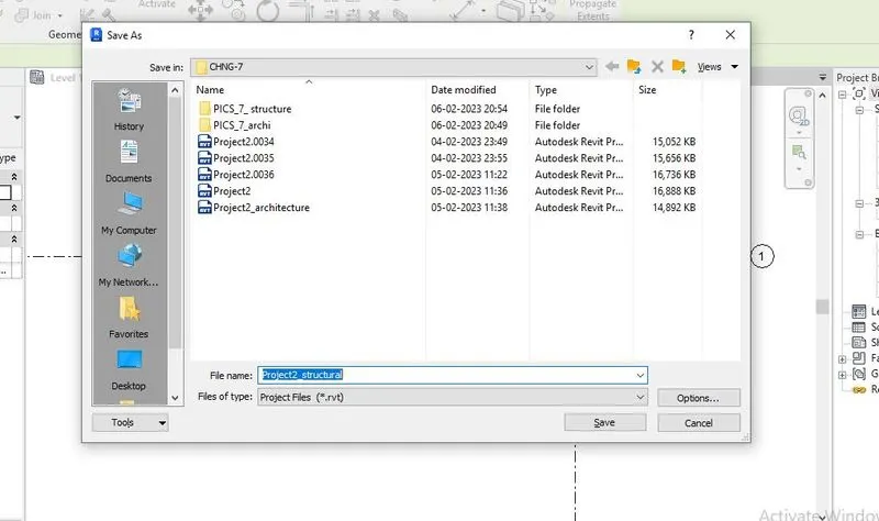
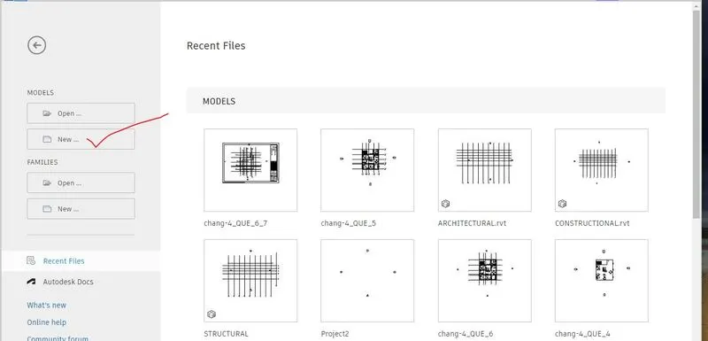
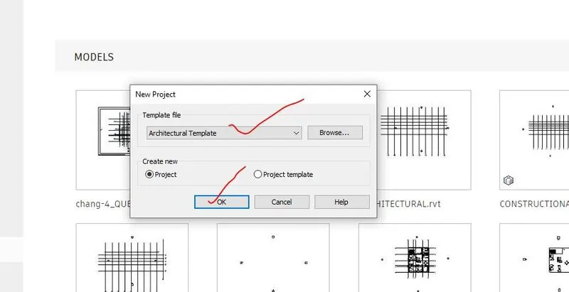
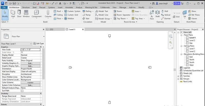
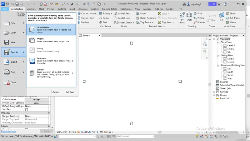
Step 1- In drafting floor plan of the apartment, first of all the architectural template has been opened and this file has been then saved as Project 2_ architecture.
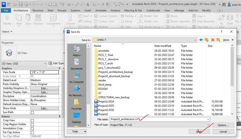
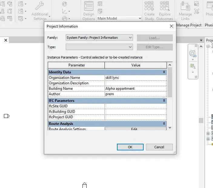
Step 2- Details information of the project has been added to the project by using the project information tool in manage tab which has been given below,
Project information of Multi-unit apartment,
- Project name- Alpha apartment
- Client name- Alpha
- Building name- Alpha apartment
- Organisation name- Prem
- Author- Skill_lync
- Project Issue date-29-02-2023
- Project number-1

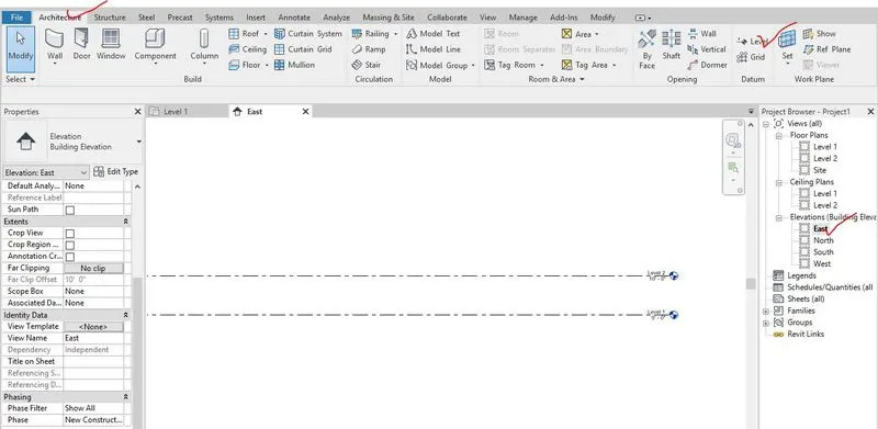
Step 3- The level of the project has been then created from architecture tab, having each level 12’ difference and then the level i.e. ground floor, 1st floor, 3nd floor, 4th floor and roof level having difference of 12’ and level between the ground and foundation level is taken as 9’.
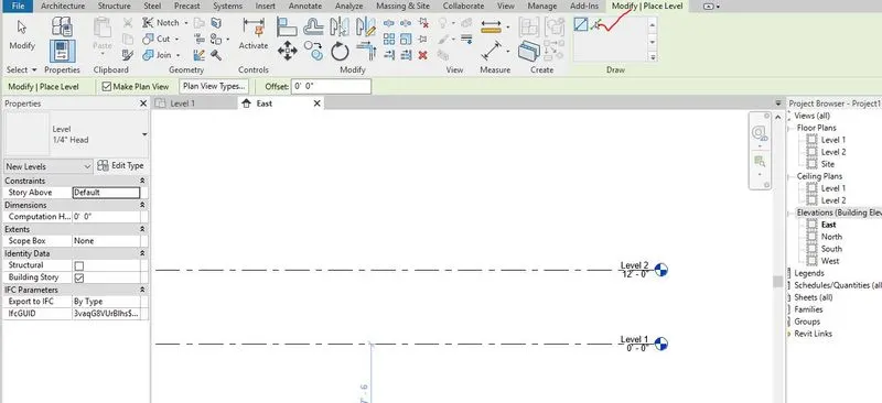
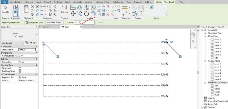
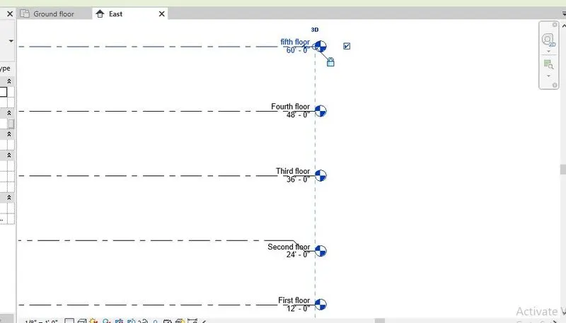
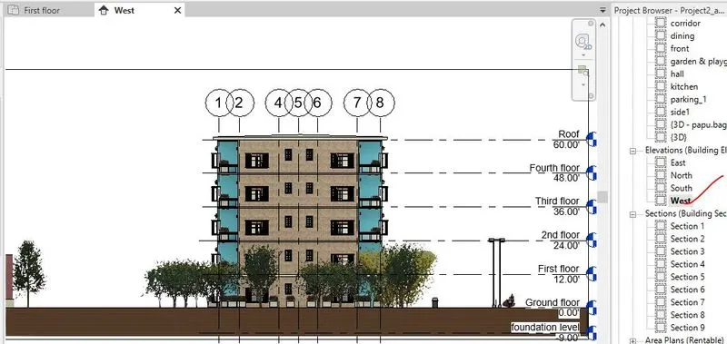
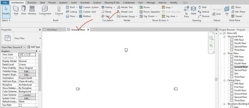
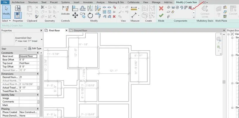
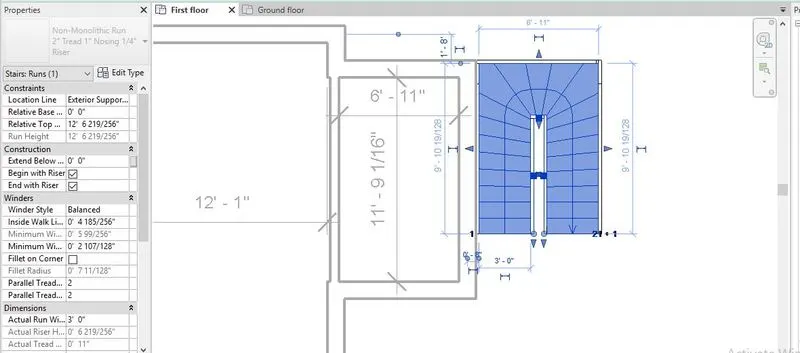
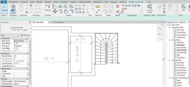
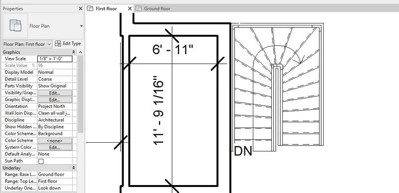
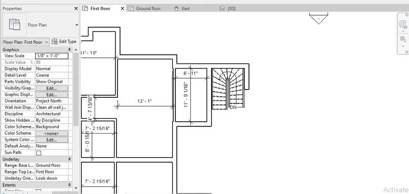
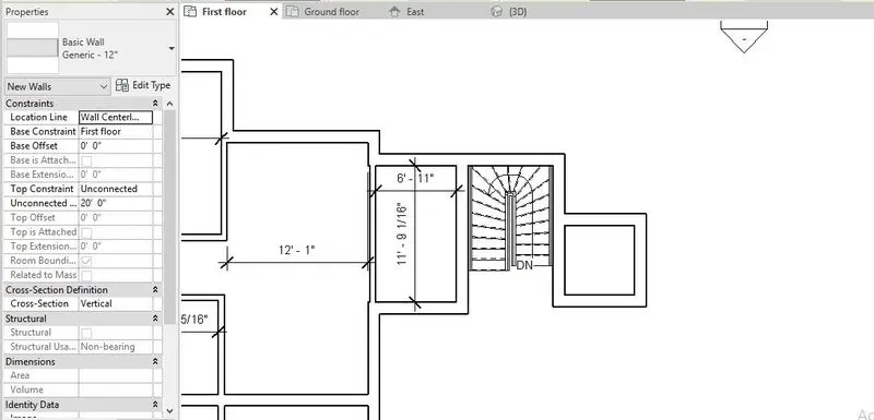
Step 4- Stairs is also created by using the stairs tool from architecture tab and floor has also been created. All the screen shots in making the stairs has been shown below,
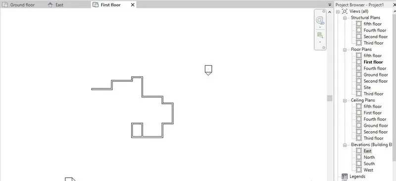
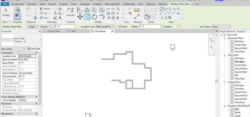
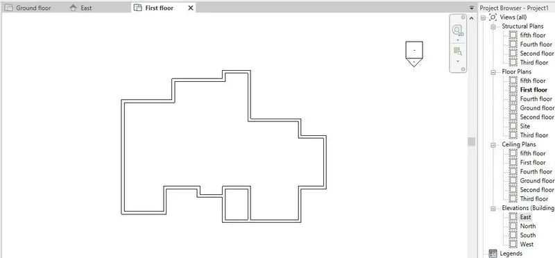
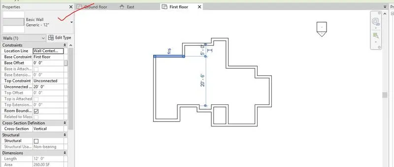
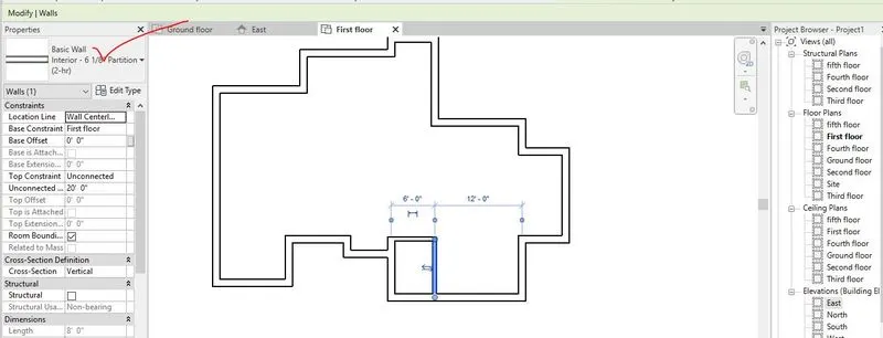
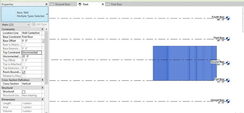
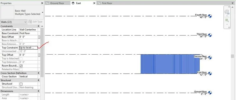
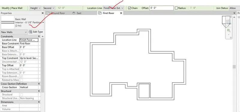
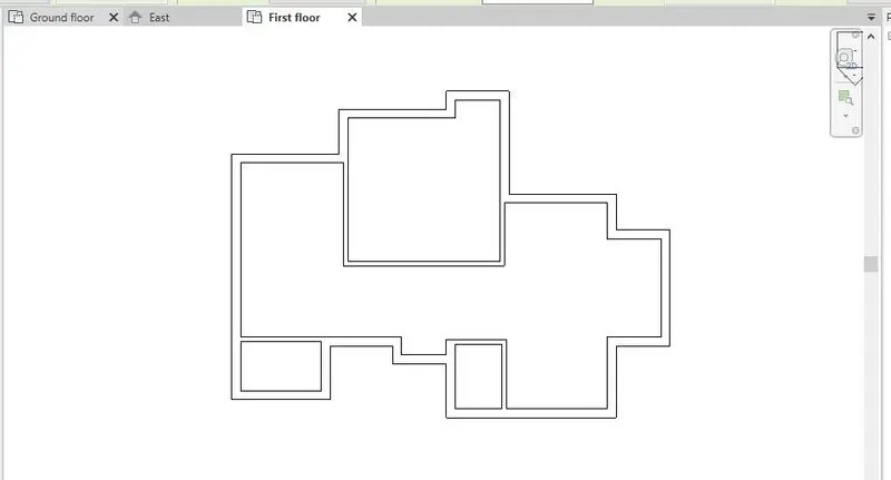
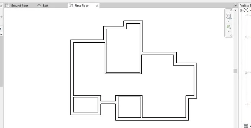
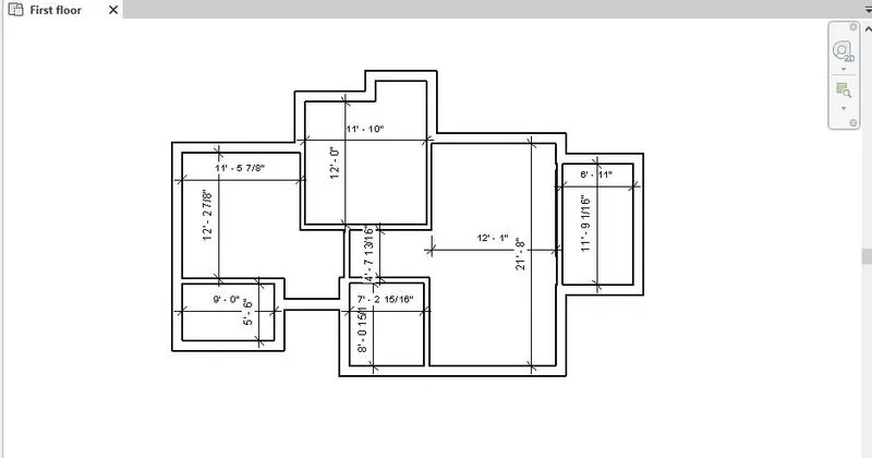
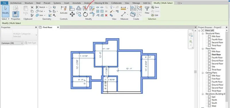
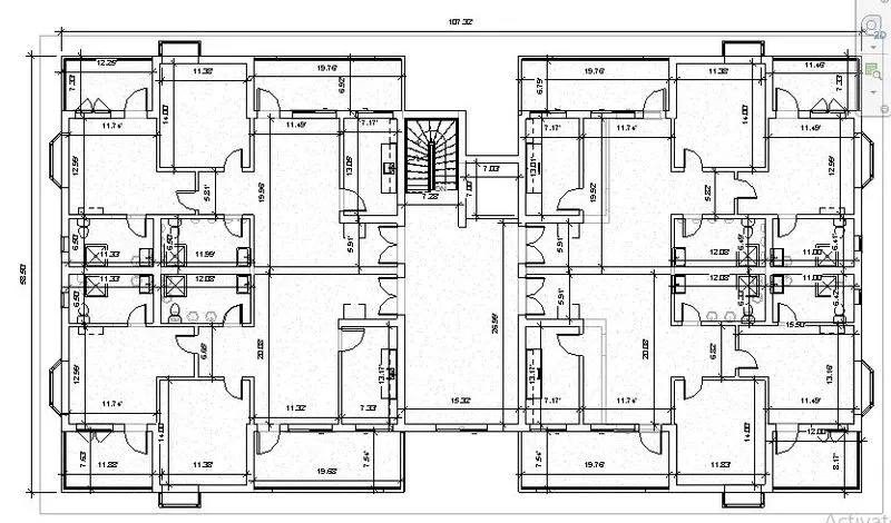
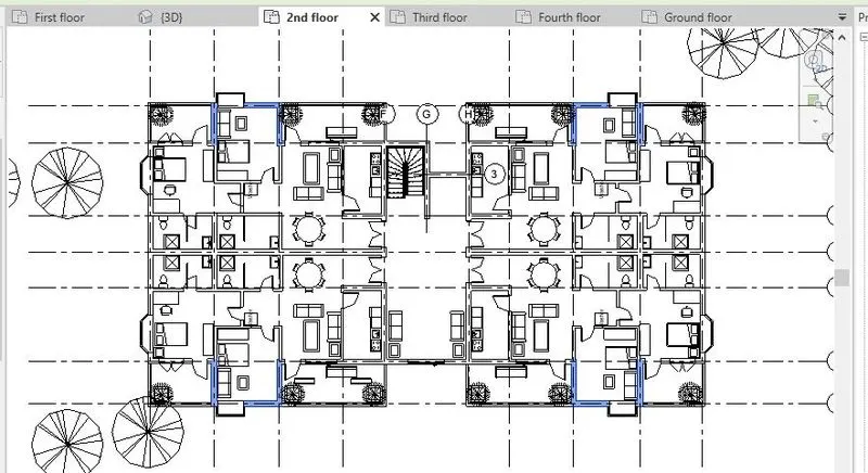
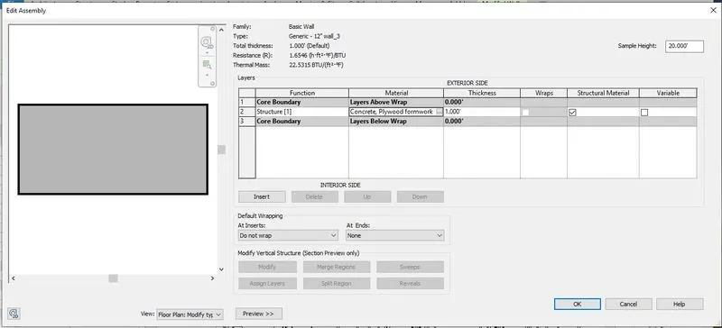
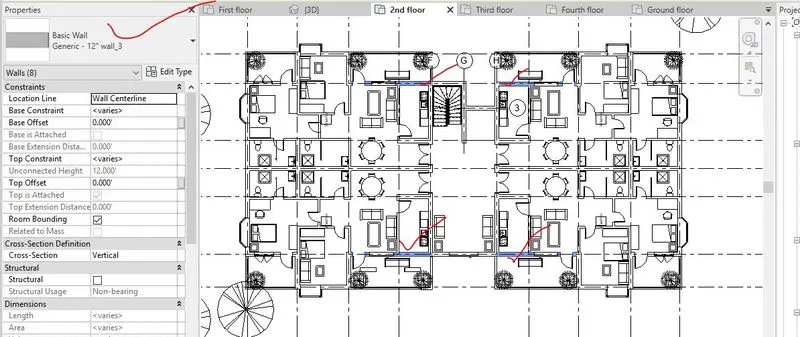
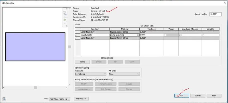
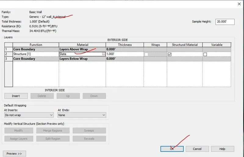
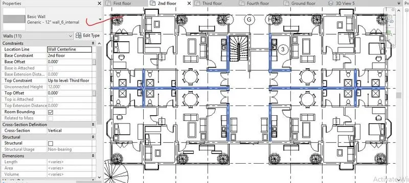
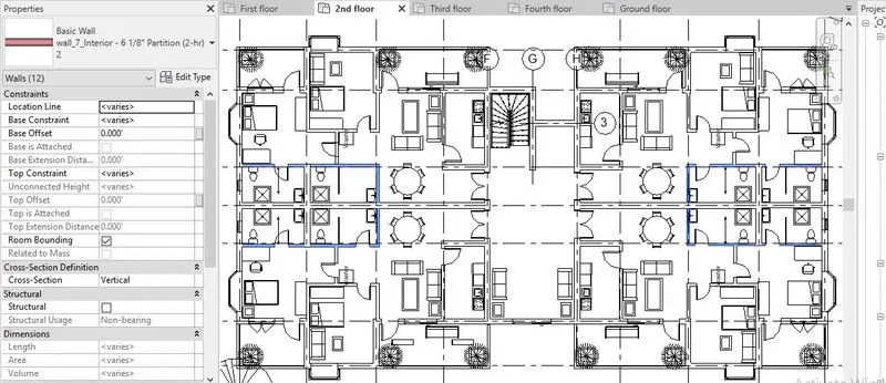
Step 5- By using the generic wall of 12”, the external wall has been created with the help of wall tool in architecture tab and with the same procedure the interior wall also has been created as per the required. The screen shots in drafting the internal and external wall has been given below,
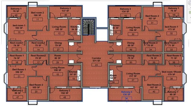
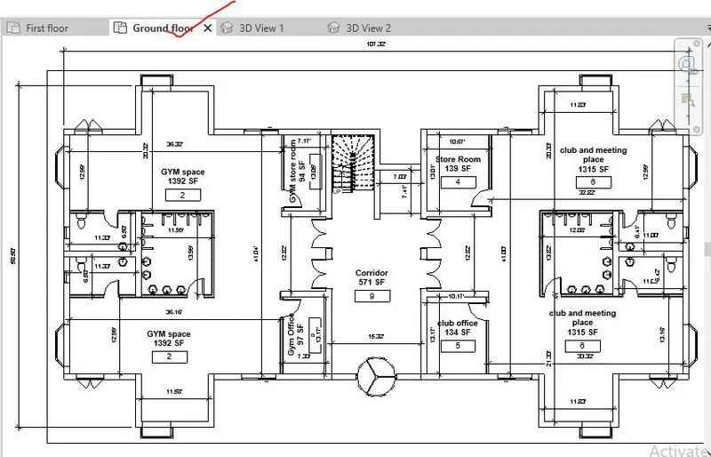
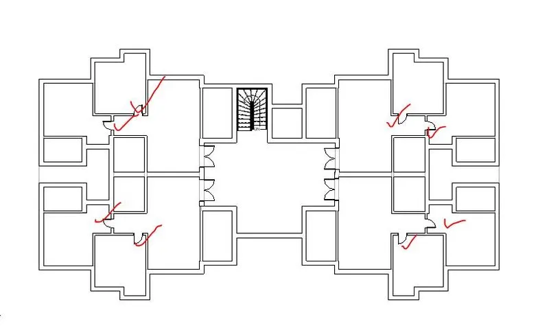
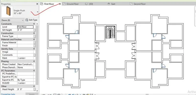
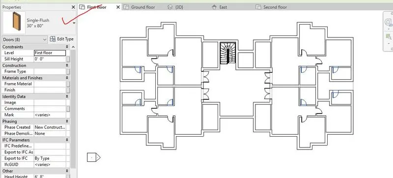
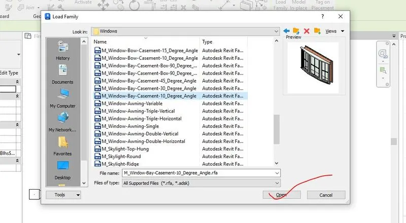
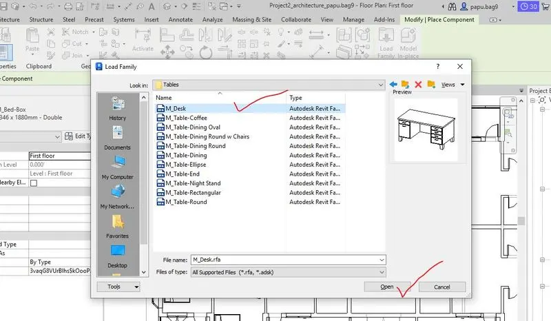
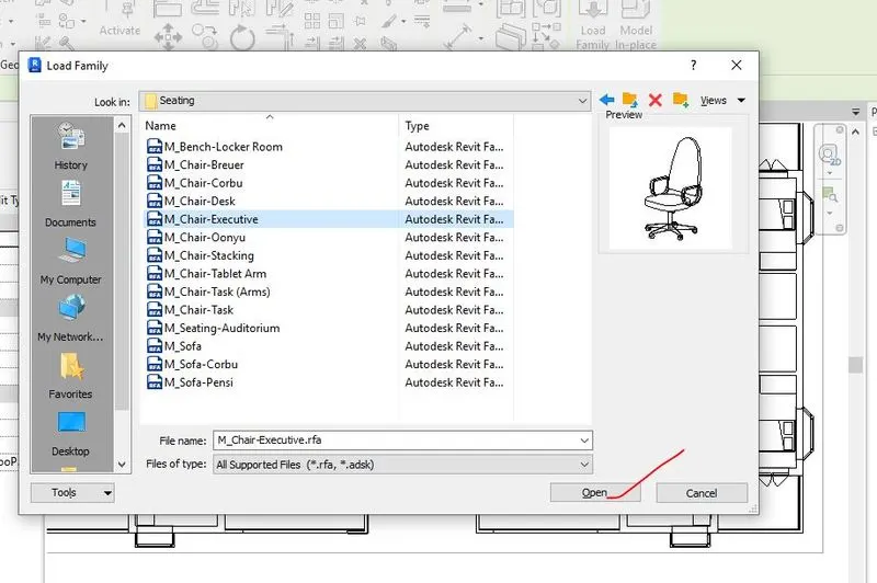
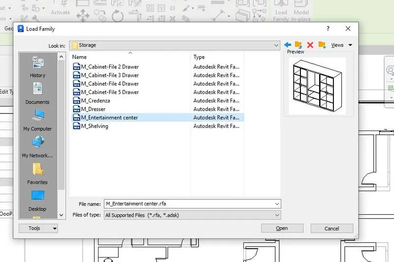
Step 6- After creation of the architectural layout plan, architectural component like door, window, furniture, plumbing, lighting and plumbing elements, is added to appropriate place.


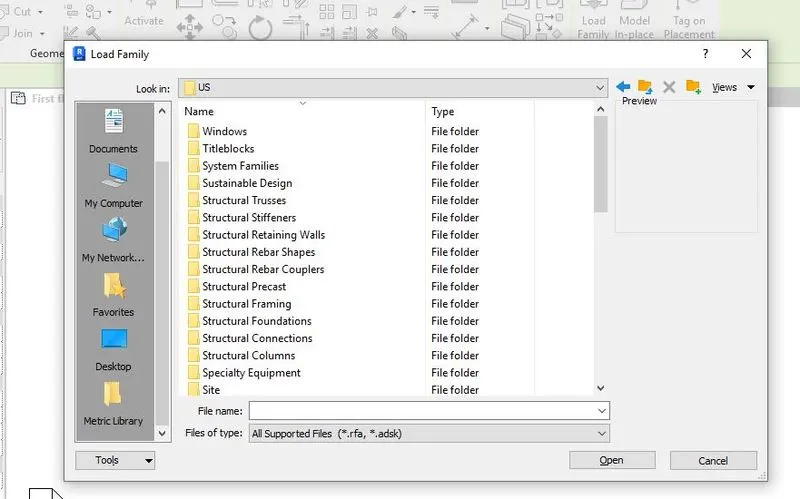
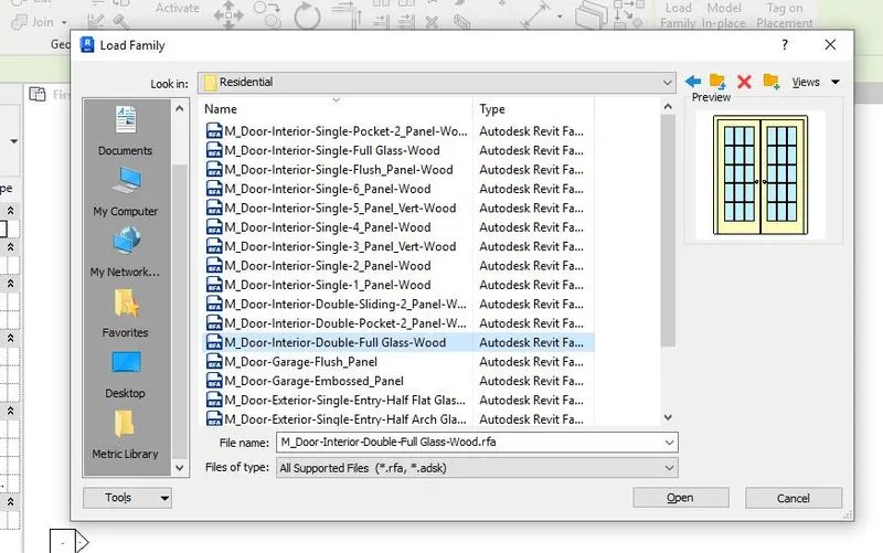
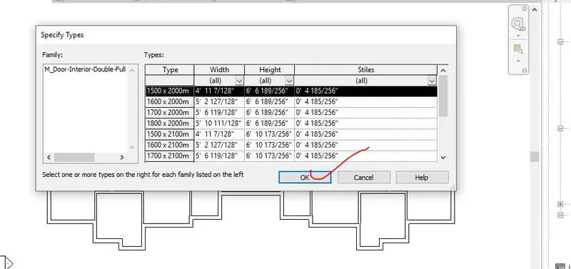
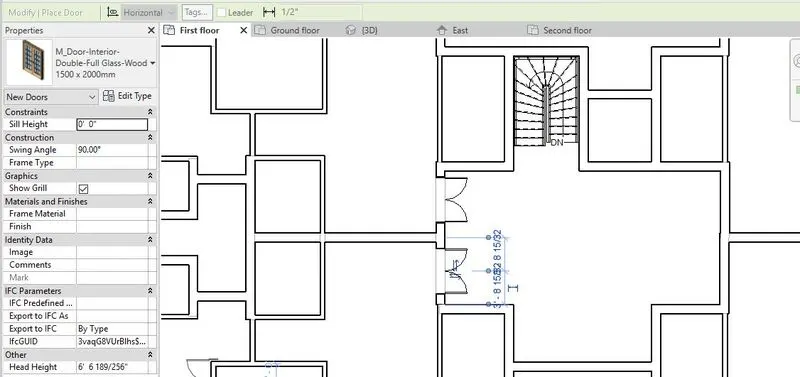
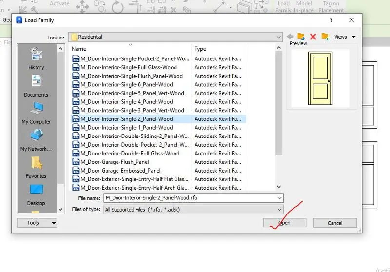
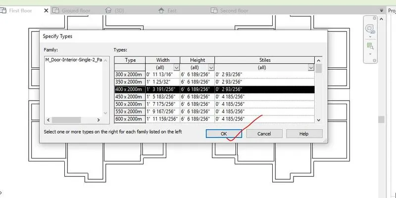


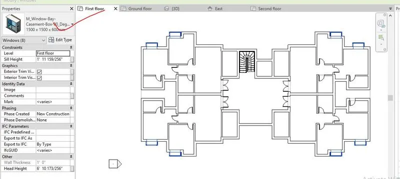
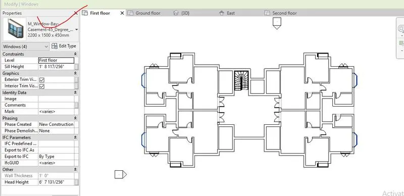
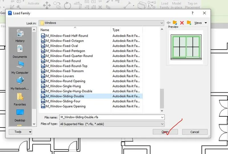
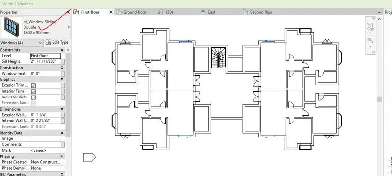
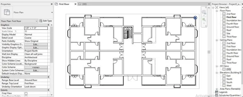
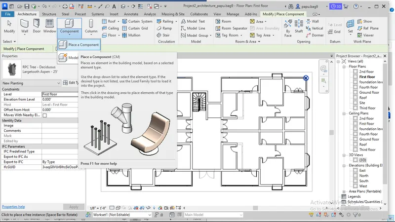

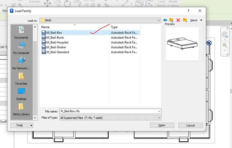

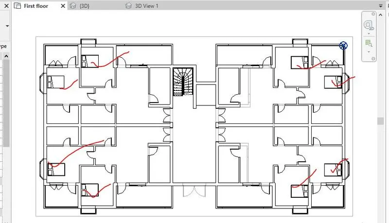
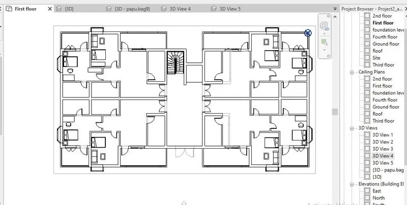
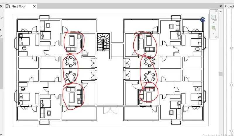
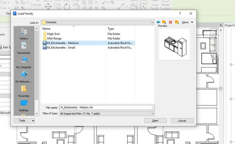
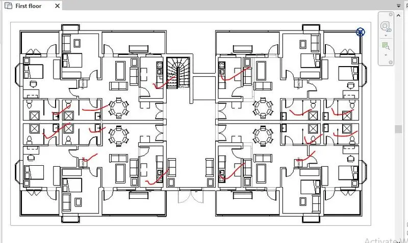
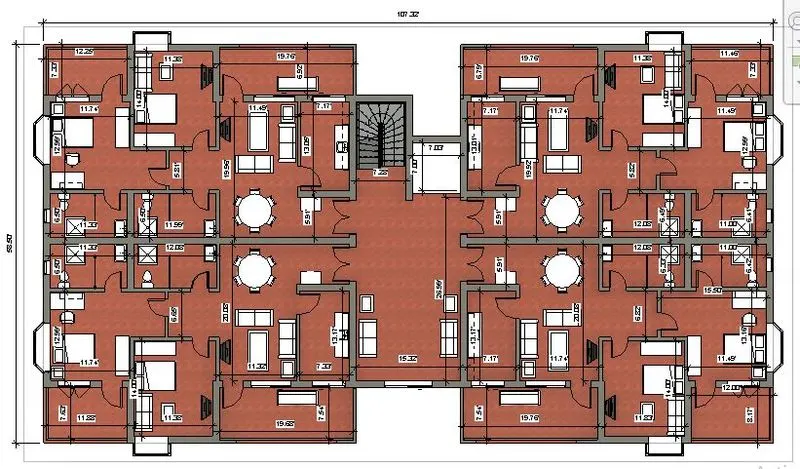
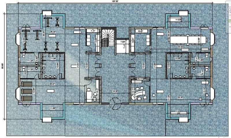
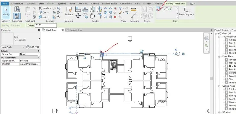
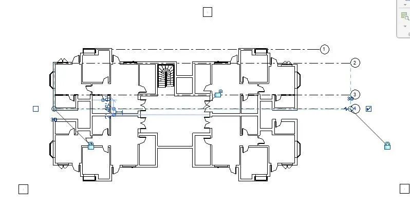
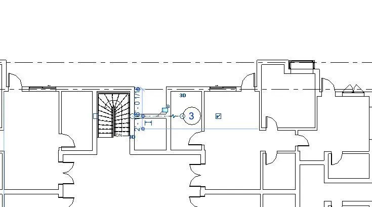
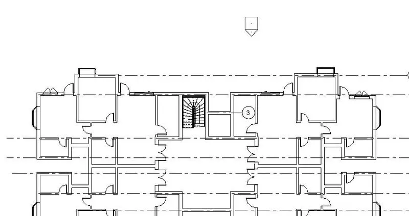
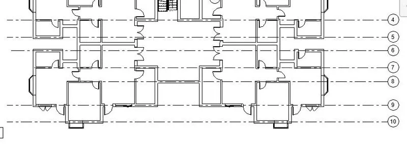
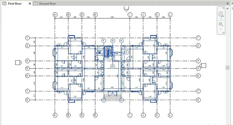
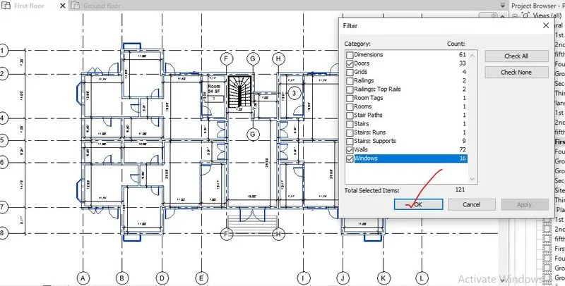
Step 7-The grid has been created by using the grid option from architecture tab. As here in this project, the floor plan with difference components of the 1st floor is same as that of 2nd. 3rd, 4th floor, so all the floor plan with same component has been added to the required different level by using copy and paste it to the selected level which has been shown below.

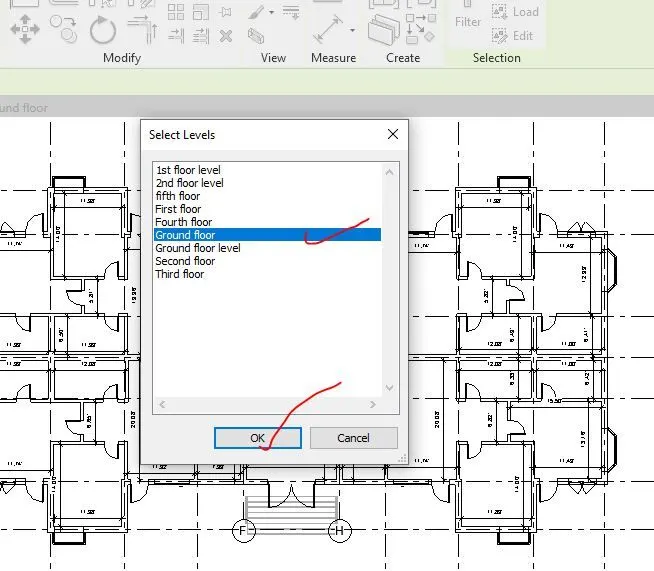
Step 8- The roof has been added to the roof level by using the roof in architecture tab which has 3-degree slope. And the open space for stairs and elevator has been created by using the shaft tool in architecture tab.
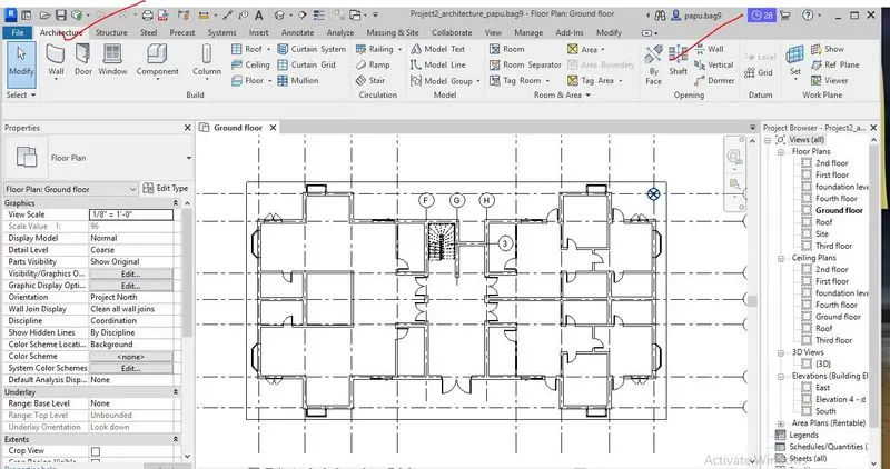
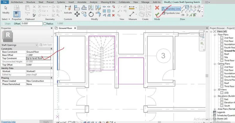
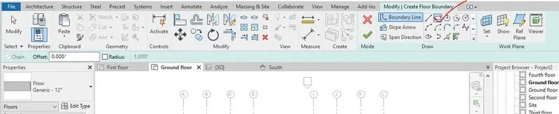
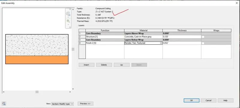
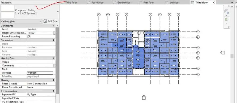
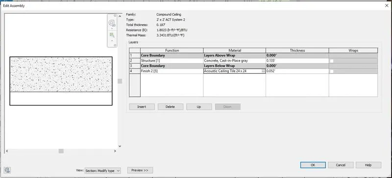
Step 9- After creation of roof and all the floor, the ceiling is created by using ceiling tool. Here in this project, the ceiling height is 10’ from floor level and the ceiling is created for all the floor.

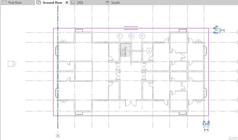
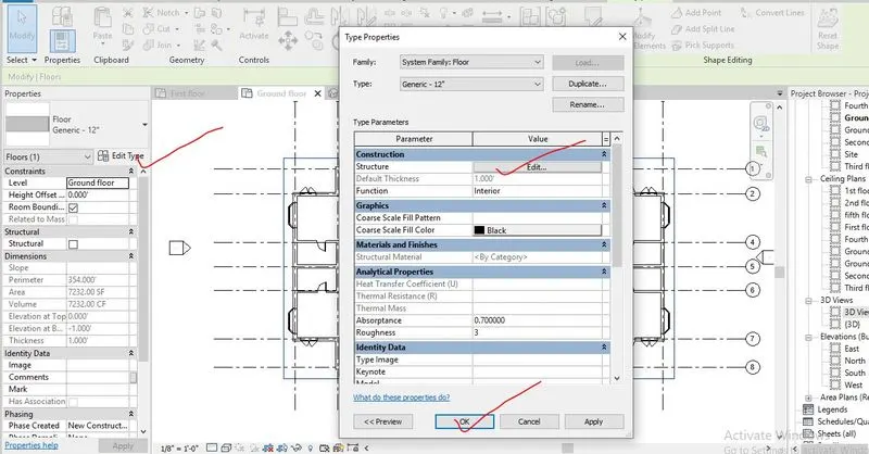
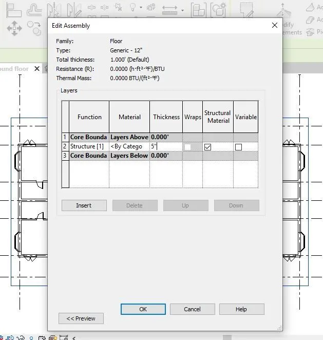

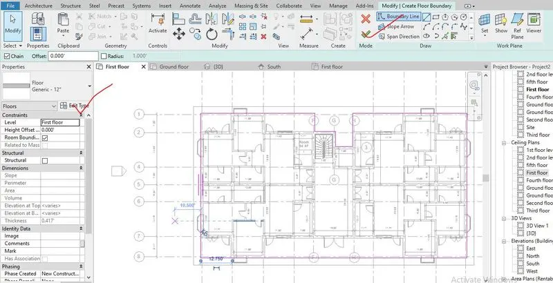
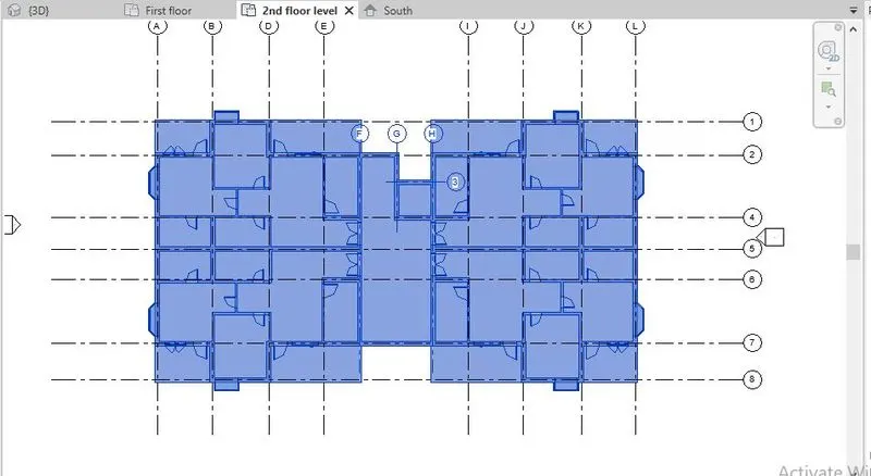


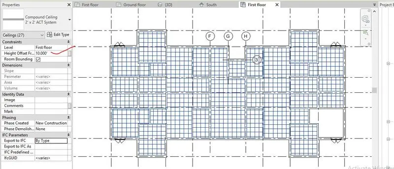
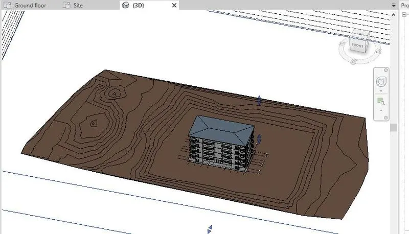
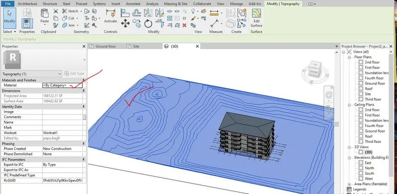
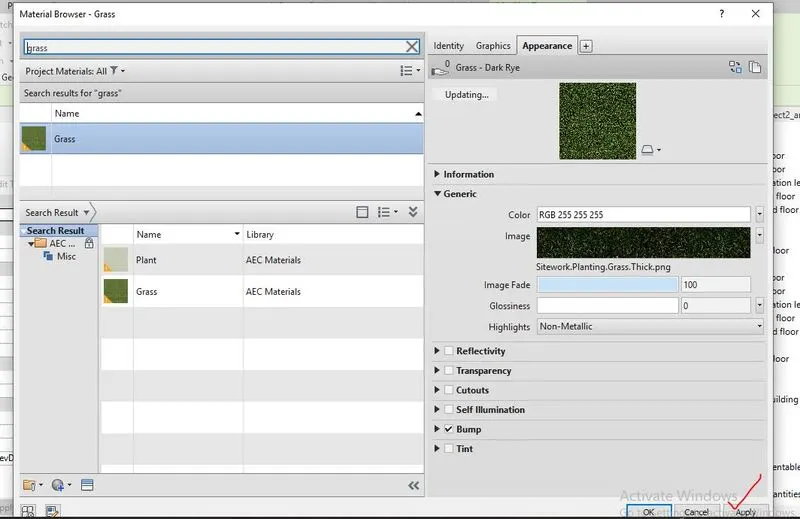
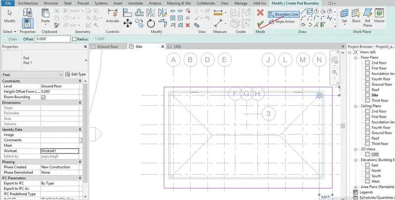
Step 10- Topography of surrounding of apartment has been created by taking approximate level of the ground by using top-surface tool from massing and site and the material of top-surface is taken as grass.
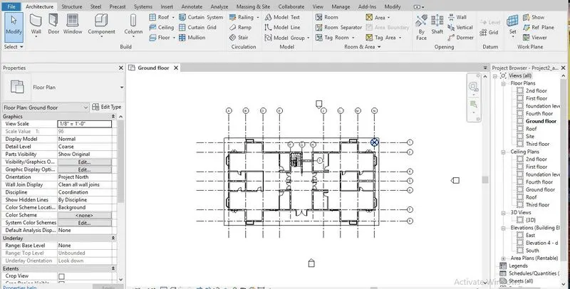
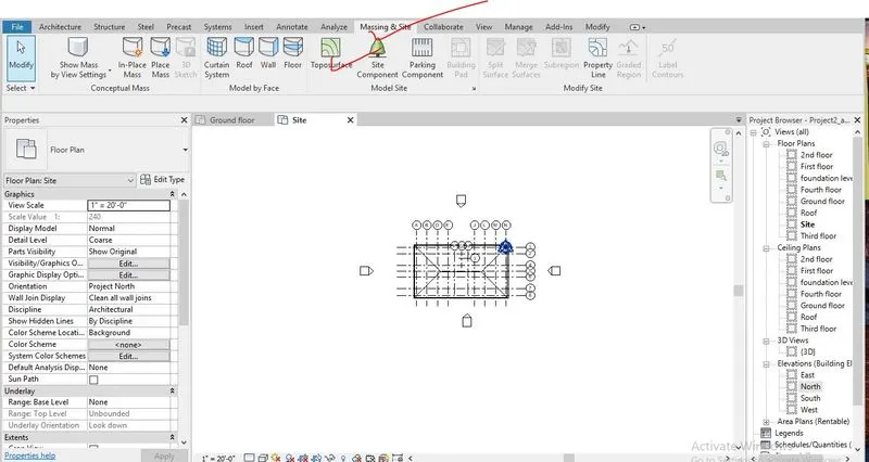
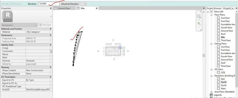
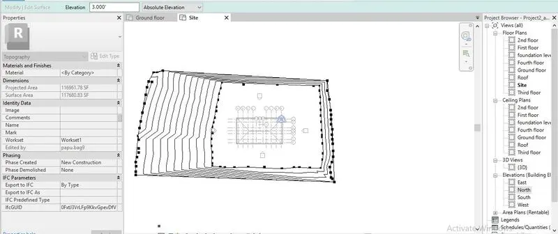
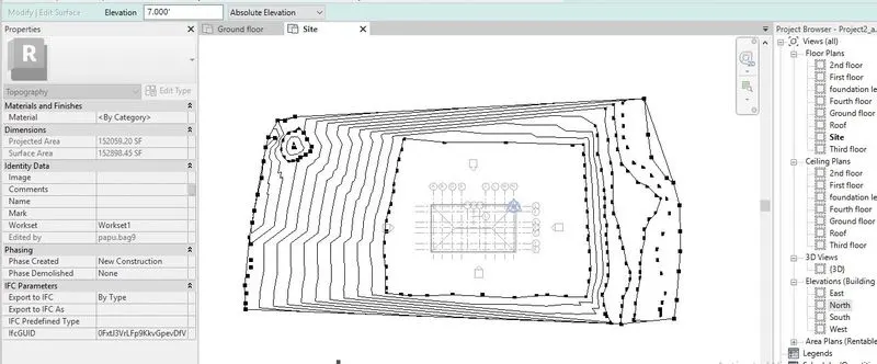
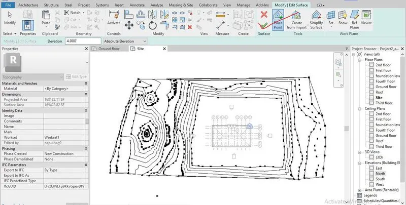


Step 11- Site component like tree, parking, plants has been added to site by using the site component tool from massing and site tab.

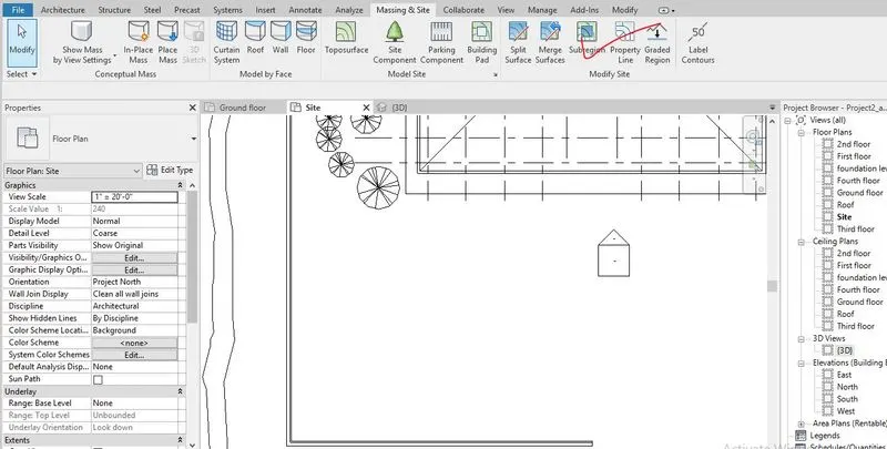
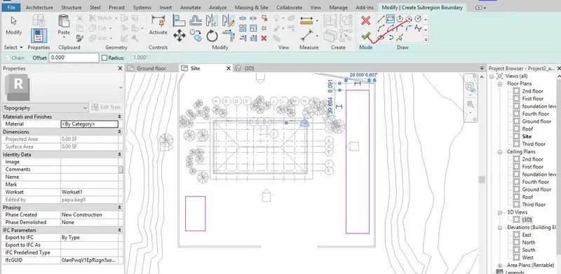
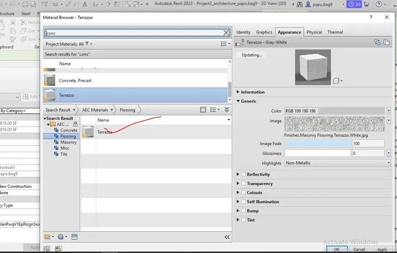

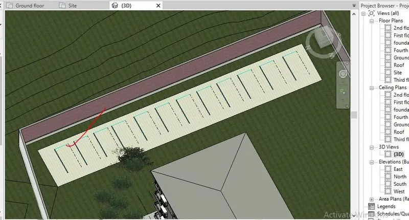
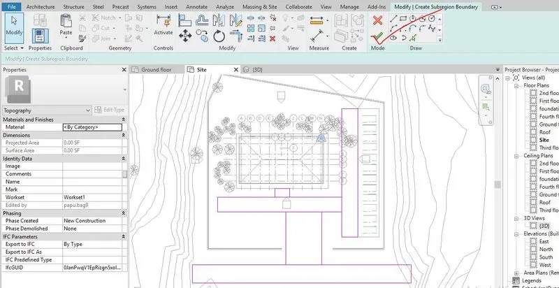
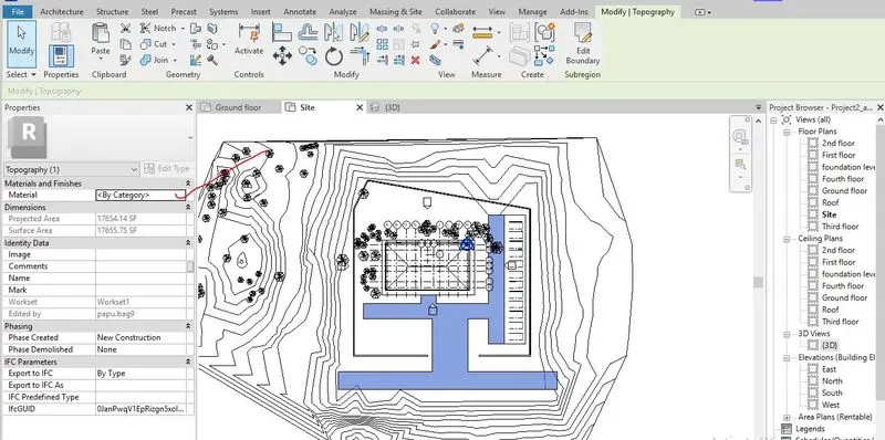
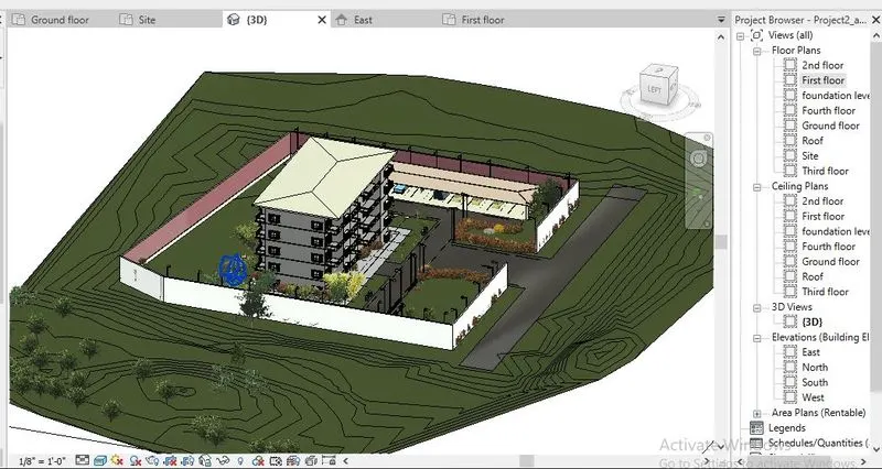
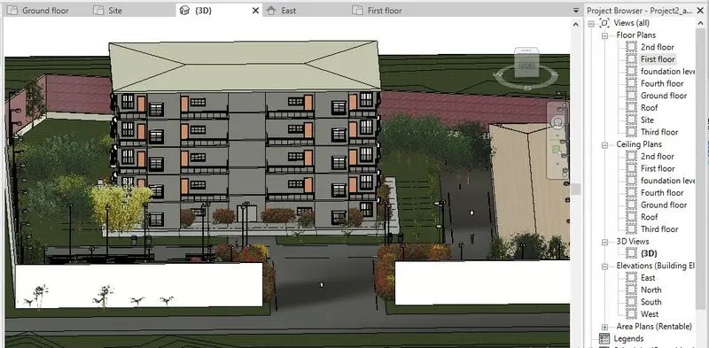
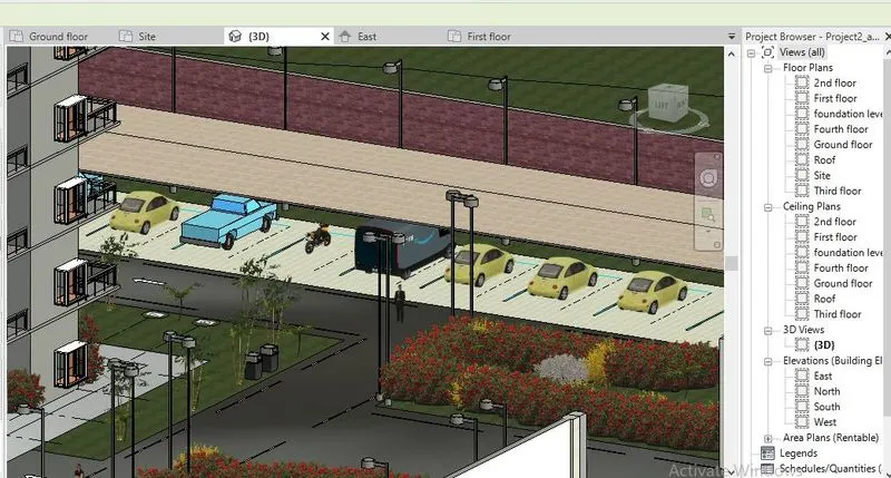
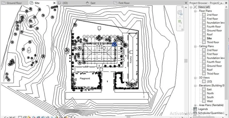
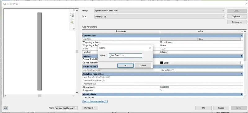
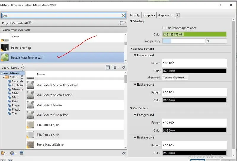
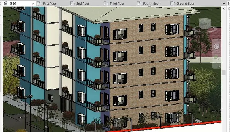
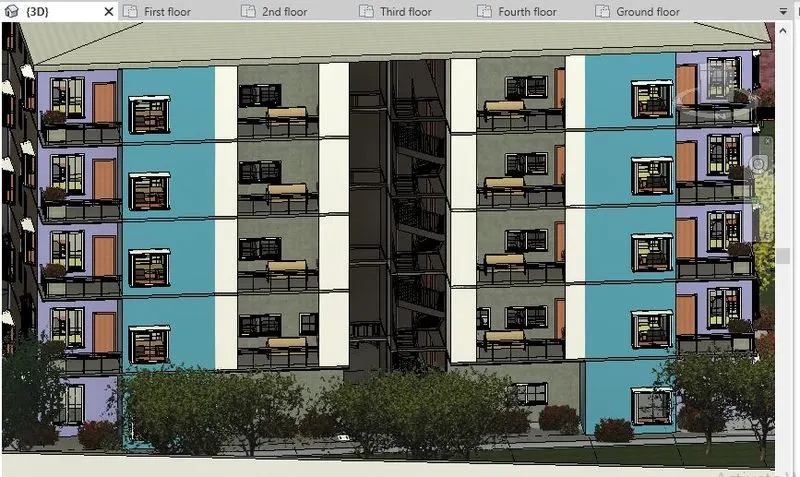
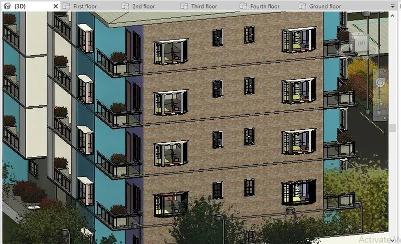
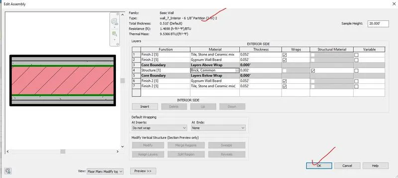
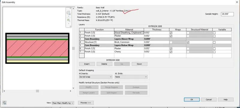
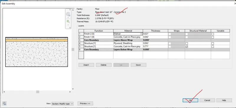
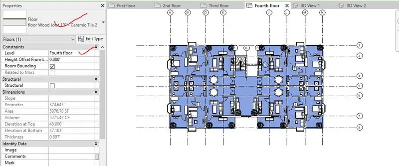
Step 12-Now, the appropriate material for different type components has been added by using edit type option in the propertied browser. All the appropriate material type of different components like wall, door, floor, roof, railing in this project that has been shown below.
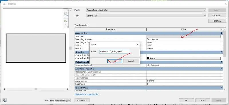
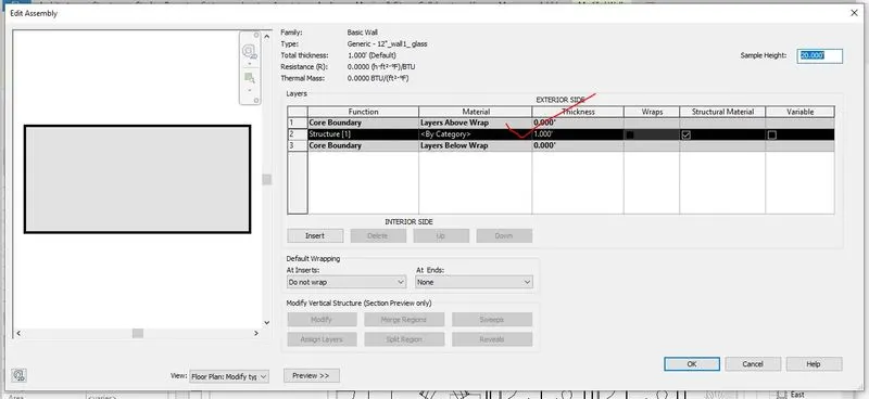
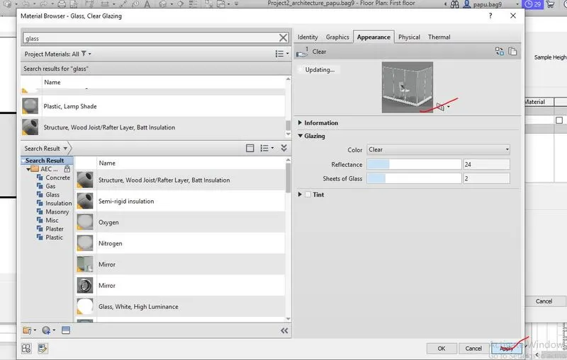
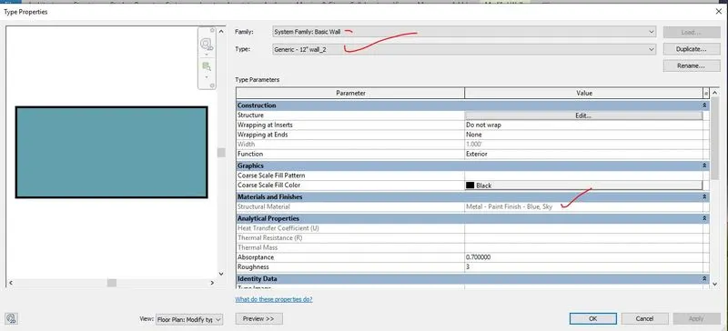
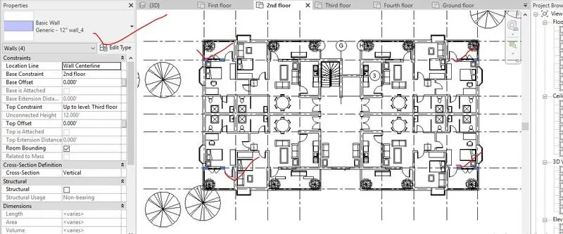
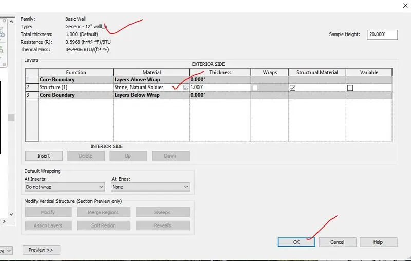
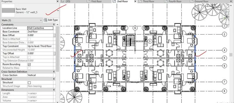
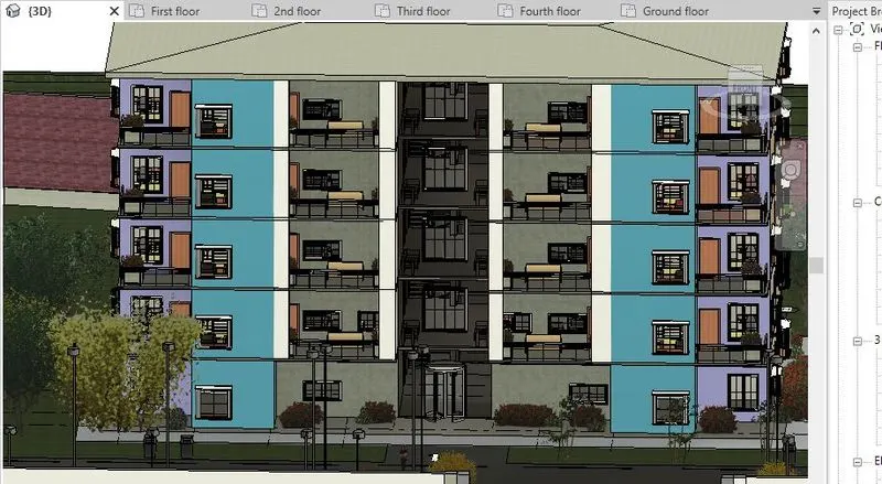
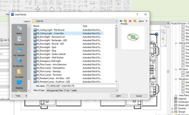
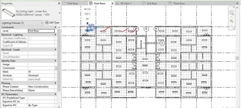
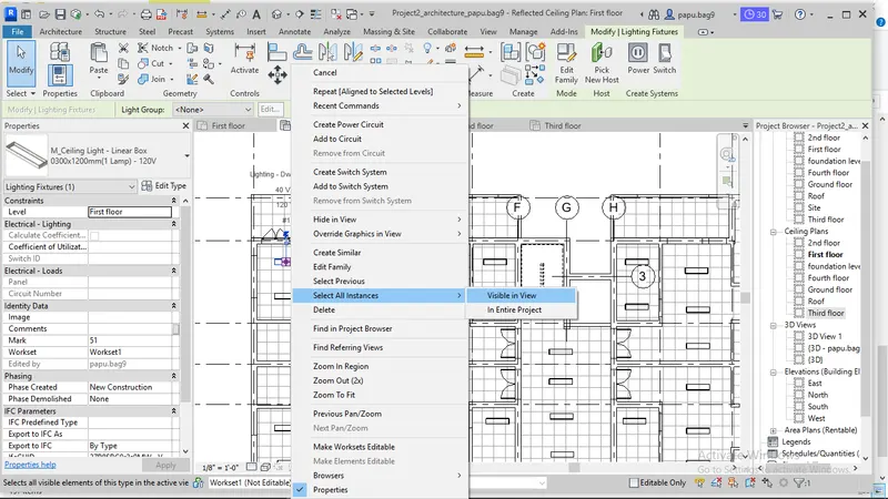
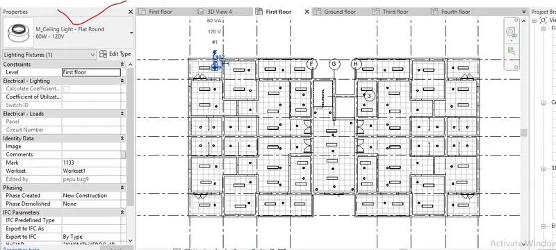
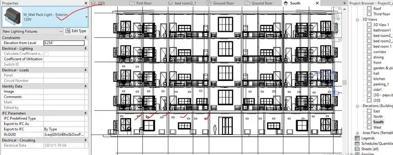
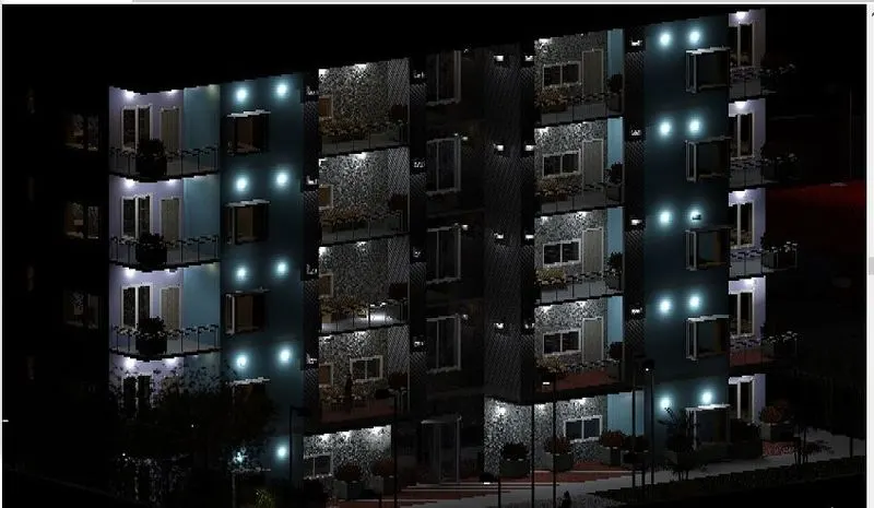
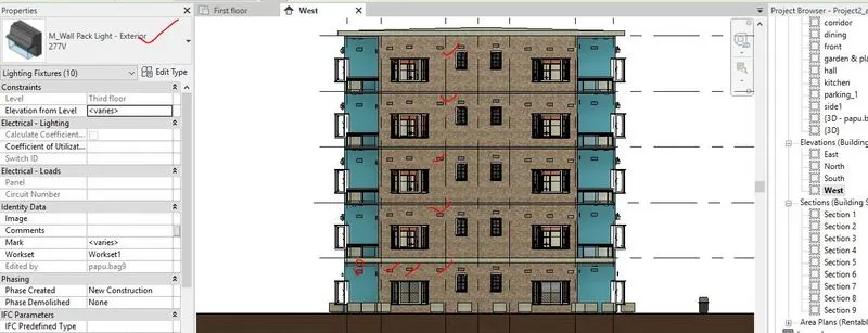
Step 13- As per the light requirement, the interior and exterior light has been added to this project, that has been shown in below.
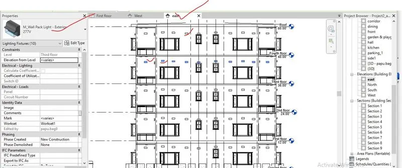
4.3 Results
All the results in drafting and modelling the architectural model with all the components with appropriate materials is shown below,
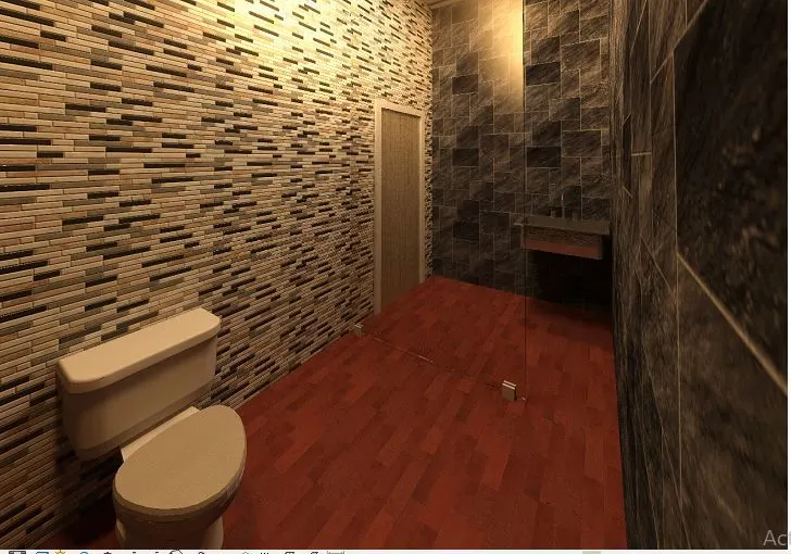
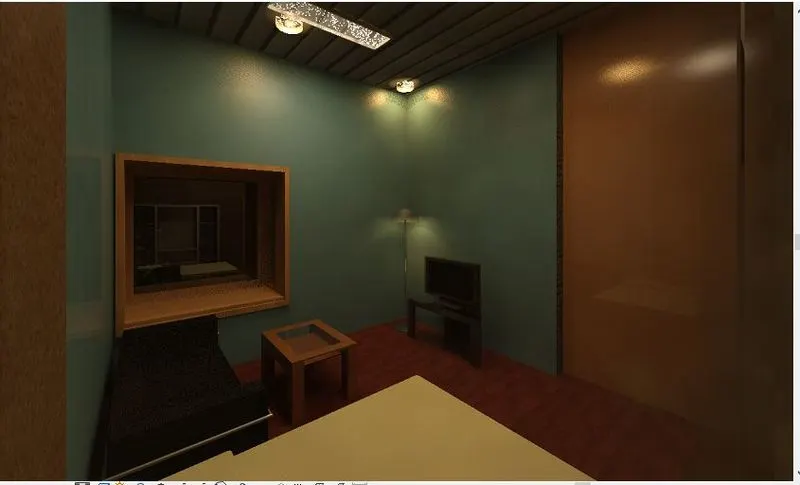
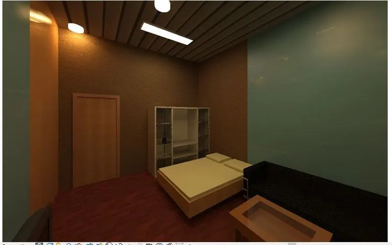
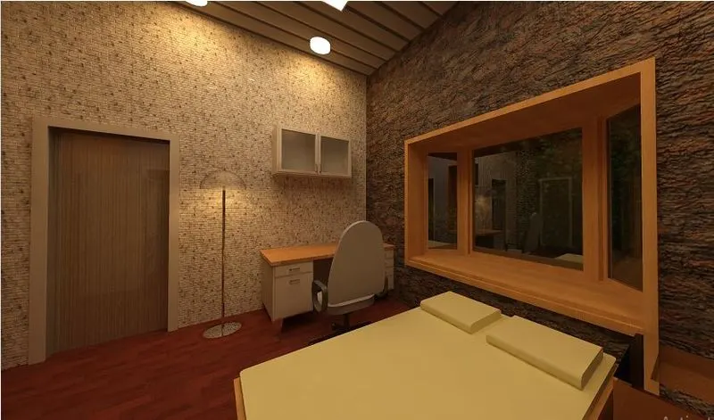
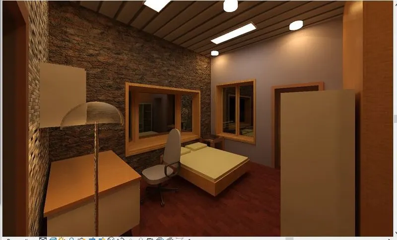
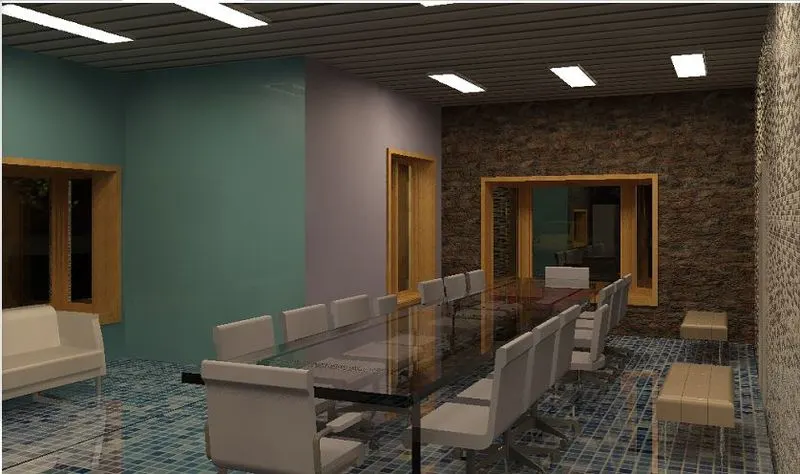
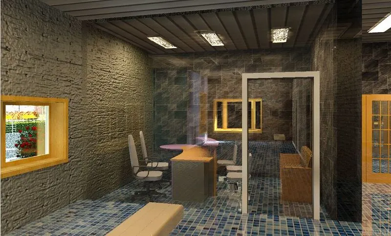
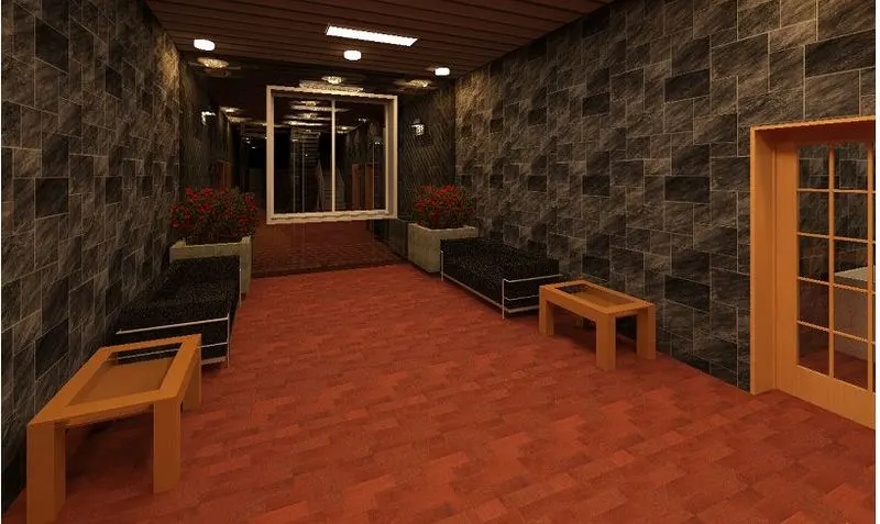
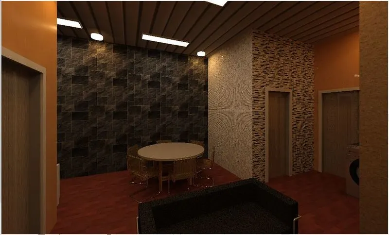
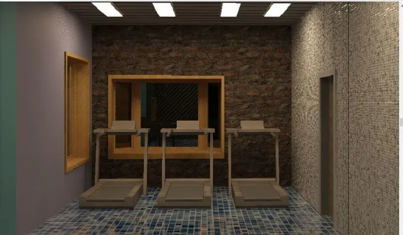
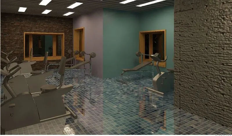
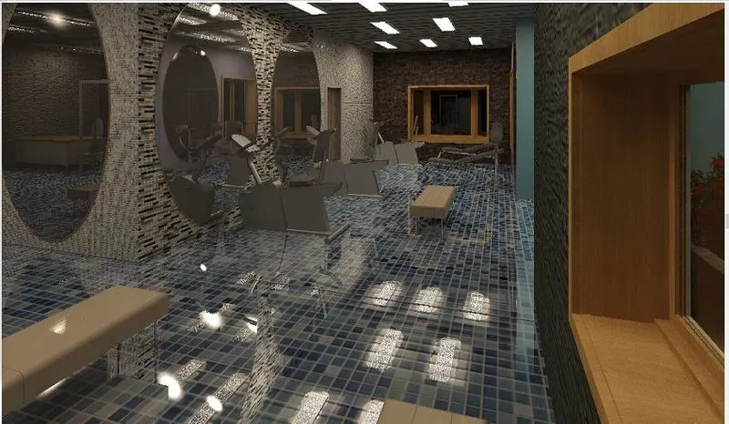
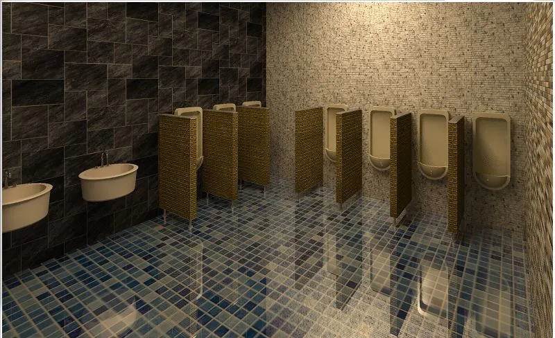
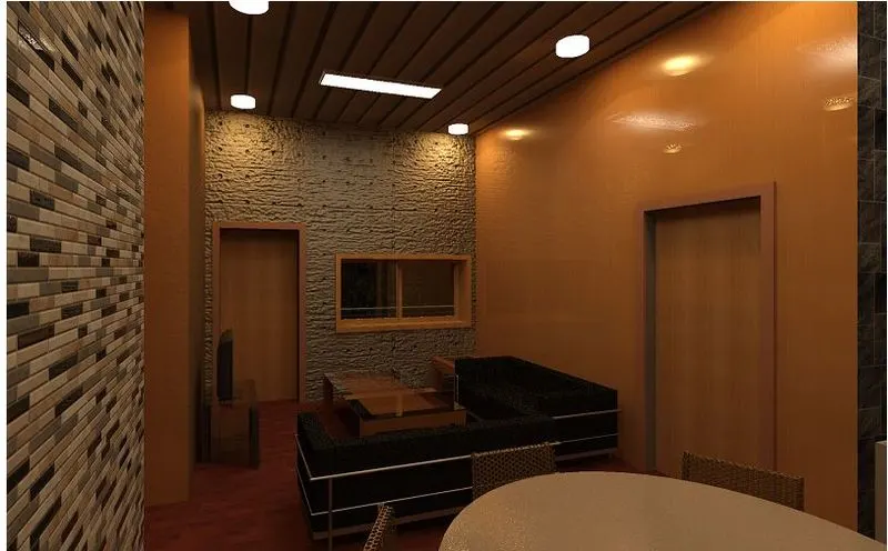
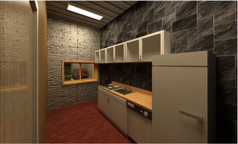
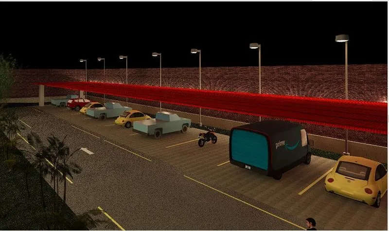
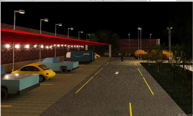
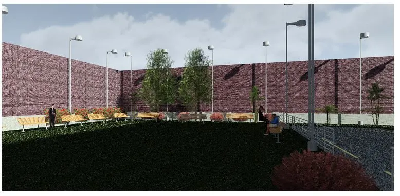
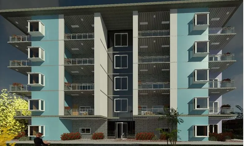
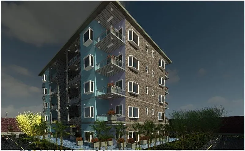
- The results of including the Architectural components like Wall Layout with appropriate material and finishing, Exterior façade with fancy finish, Interior partition walls to size rooms, Components to add details to a room (Desk, Chair, Lighting, plumbing fixtures), stairs Elevators, one side of the building with curtain walls and glass panel, interior and exterior lighting fixtures and topographic components from outside (Trees, Parking, Plants) to add details to the model which is based on structural component by using the Architectural template in REVIT i.e. the .rvt file is uploaded named as 'Project2_architecture'.
-----------------------------------------------------------------------------------------------------------------------------------------
5) Provide a set of drawings in an architectural and structural model to list the following details with categories and appropriate sheet templates included
a. Floor Plans with Annotations
b. Elevations
c. Sections
---------------------------------------------------------------------------------------------------------------------------------
5.1 Aim of the Project- To provide a set of drawings in an architectural and structural model to list the following details with categories and appropriate sheet templates including Floor Plans with Annotations, Elevations and Sections.
5.2 Procedure-
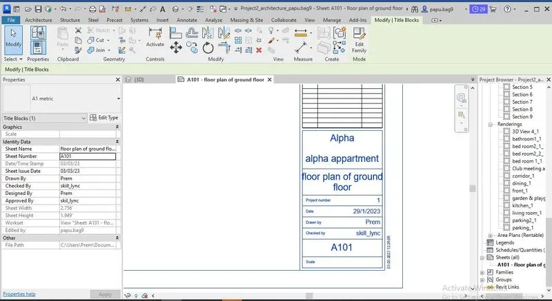
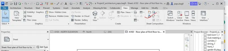
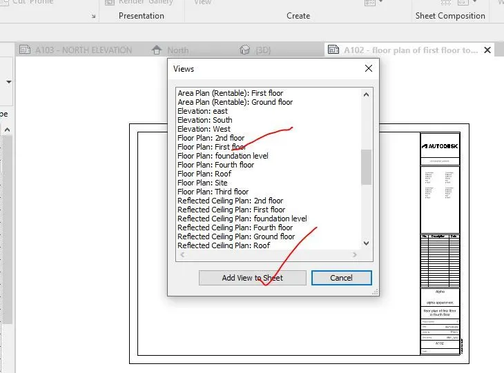
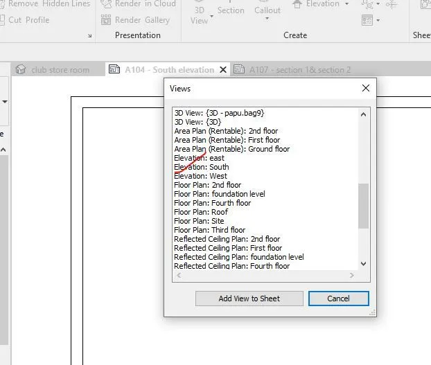
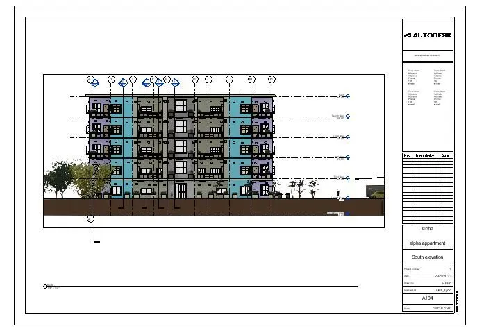
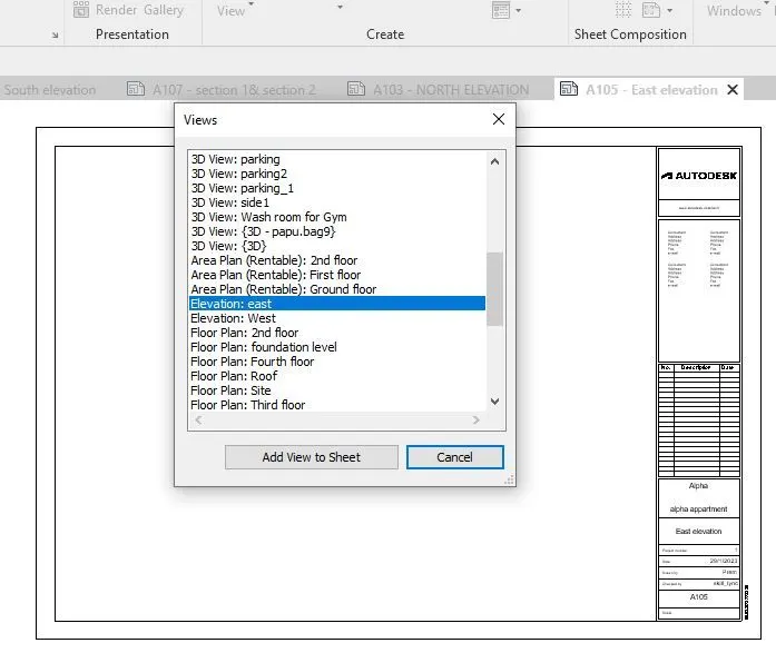
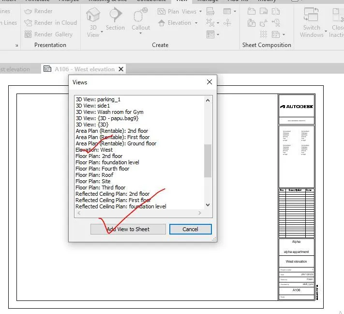
Step 1- To add the set of drawings in architecture as well as the structural drawing of floor plan with annotation, different elevation and section in the sheet template, the sheet to be opened by using the sheet tool in the view tool.
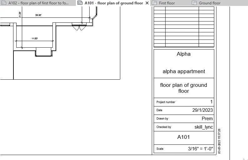
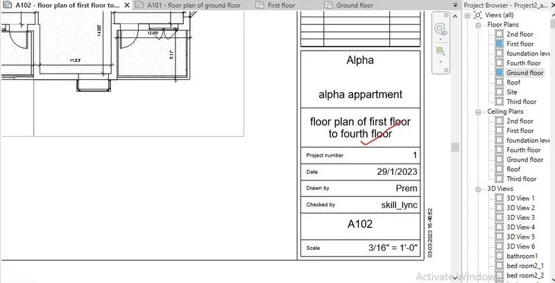
Step 2- A1 metric size of sheet template has loaded. After selection of the size of the sheet, the of the sheet with project information has been edited to the sheet. And different sheet has been added for ground floor, first floor, 2nd floor, 3rd floor and 4th floor, also
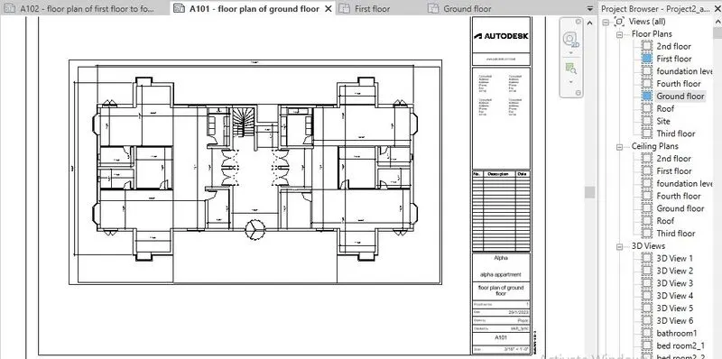
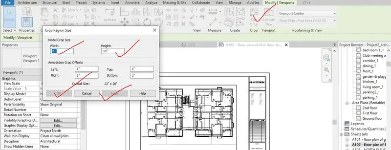
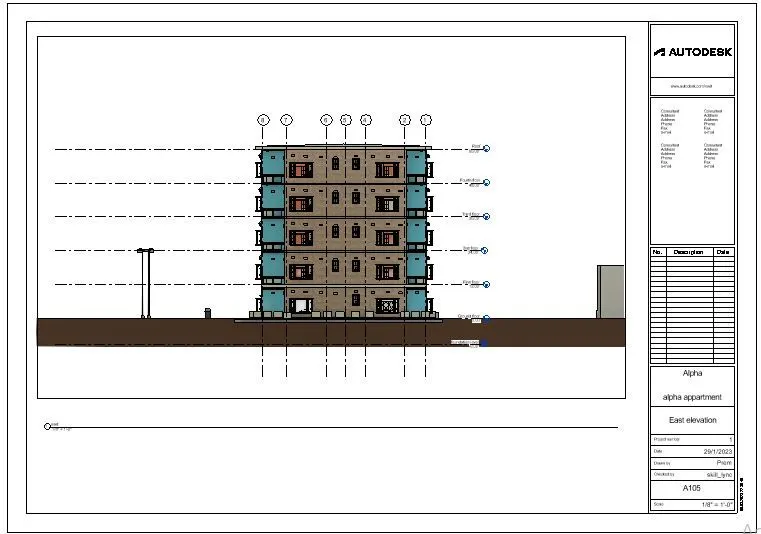
Step 3- By clicking the required drawing, the drawing can drag in to the sheet, and it can be adjusted according to the size requirement.
Here in this project the sheet has been used as name i.e. given below
A101- floor plan of ground floor
A102- floor plan of first floor to fourth floor
A103- NORTH ELEVATION
A104-South elevation
A105-East elevation
A106-West elevation
A107-section 1& section 2
A108-Section 5, Section6, Section7 & Section8
A109-Section3, Section4 & Section9
For structural template,
S.1-Section 1 &2
S.2-east elevation
S.3-north elevation
S.4-south elevation
S.5-west elevation
All the screen shots in placing the drawing in the respective sheet has been shown below,

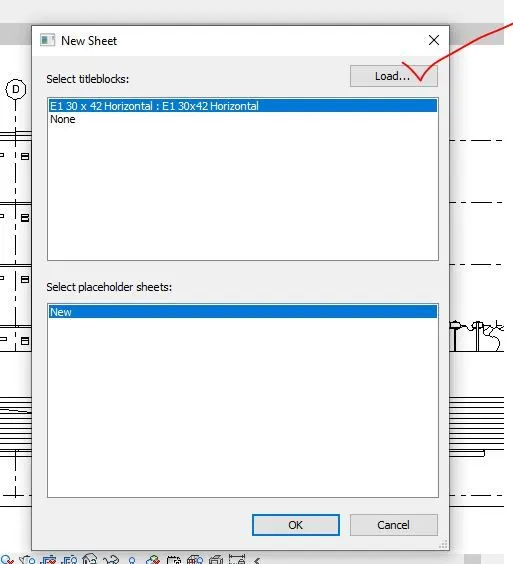
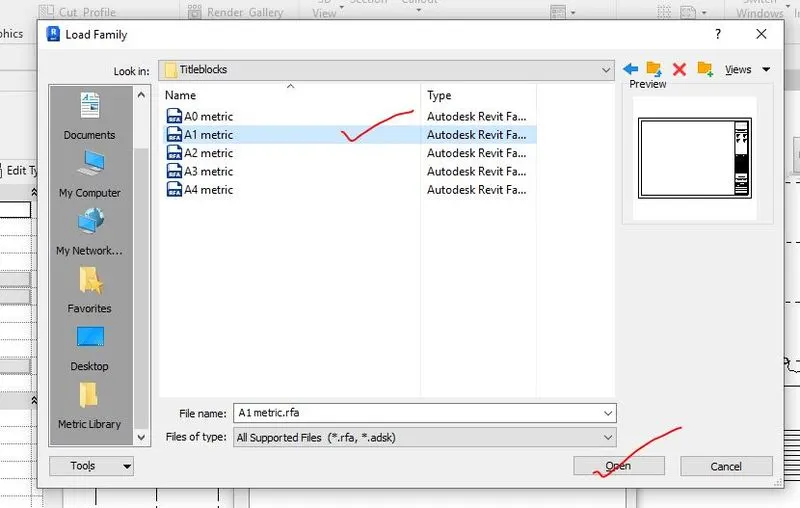
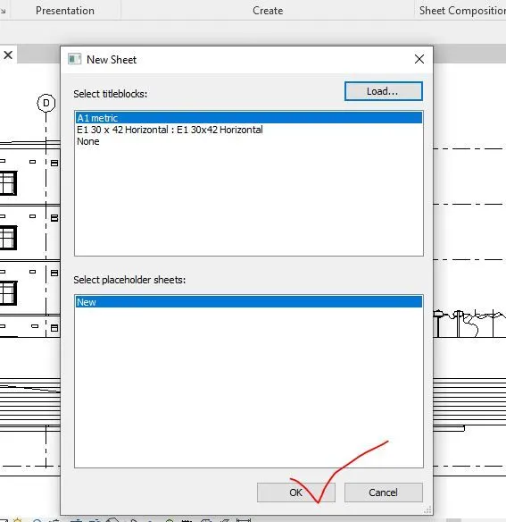

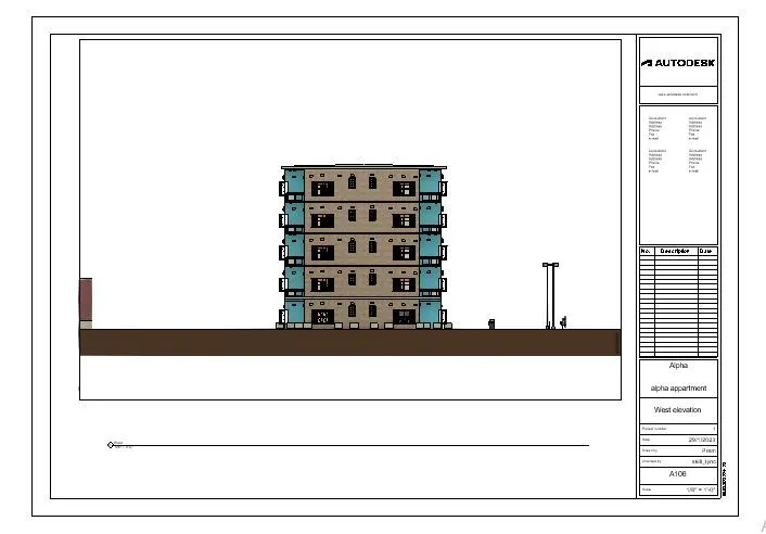
Similarly, for all the section , the respective sheet has been created which has been shown in the results.
5.3 Results-
All the results in providing a set of drawings in an architectural and structural model to list the following details with categories and appropriate sheet templates including Floor Plans with Annotations, Elevations and Sections. in REVIT is shown below,
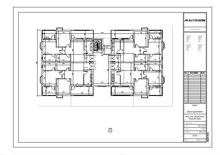
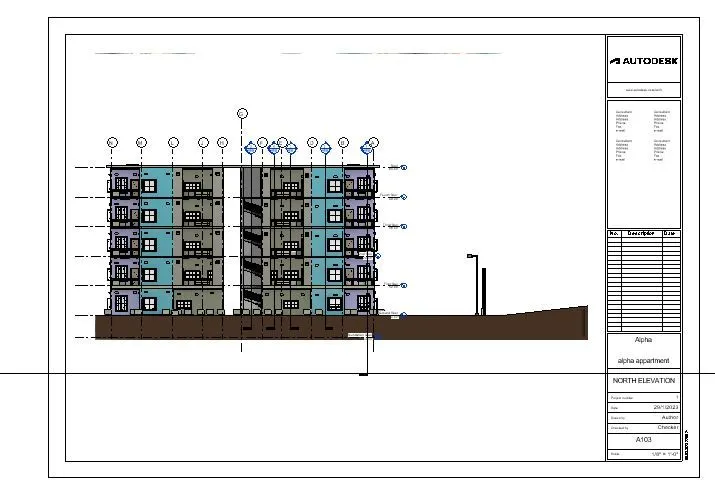
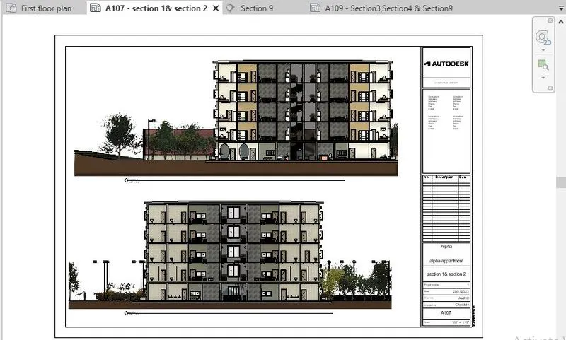
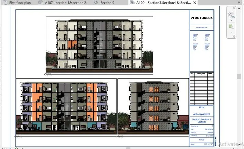
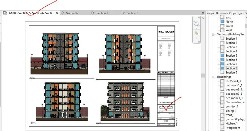
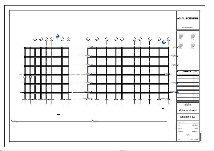
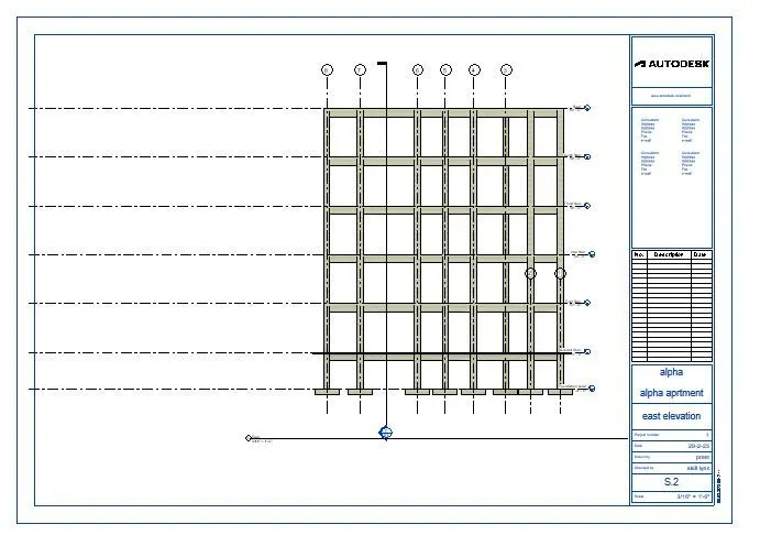
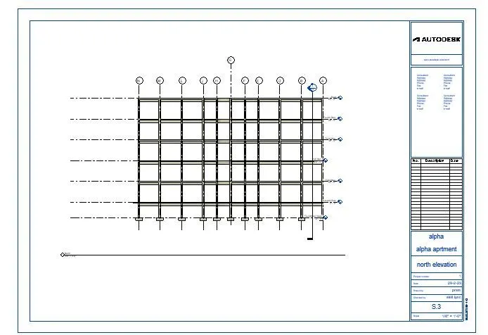
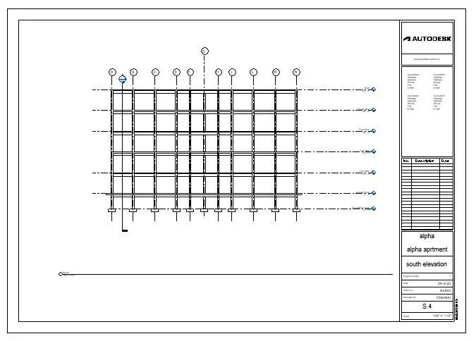
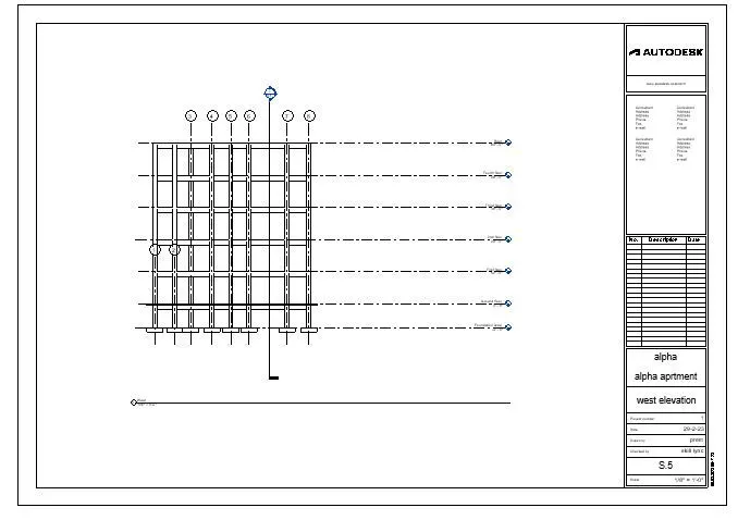
- The results of providing a set of drawings in an architectural and structural model to list the following details with categories and appropriate sheet templates including Floor Plans with Annotations, Elevations and Sections in REVIT i.e. the .rvt file is uploaded named as 'Project2_architecture'.
------------------------------------------------------------------------------------------------------------------------------
6) Using the Rendering settings, Render images of the 3D model produced and include the rendered images to the drawing sheets
a. Rendering from interior rooms
b. Rendering from out showing topographic features
c. Rendering through structural framing.
-----------------------------------------------------------------------------------------------------------------------------------------
6.1 Aim of the project- To use the Rendering settings, Render images of the 3D model produced and include the rendered images to the drawing sheets i.e. Rendering from interior rooms, rendering from out showing topographic features and Rendering through structural framing.
6.2 Procedure-
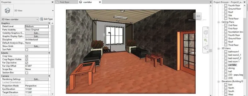
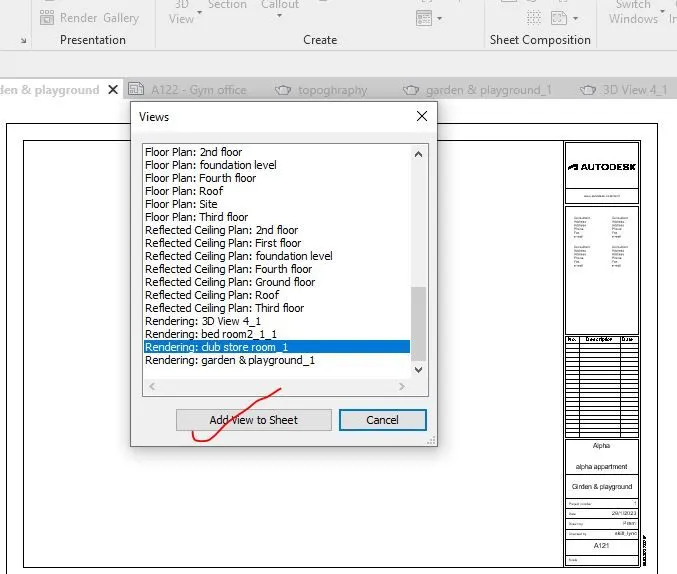
Step 1- To render the 3d view, the view has to be set up by using the camera view from the view tab in appropriate place.
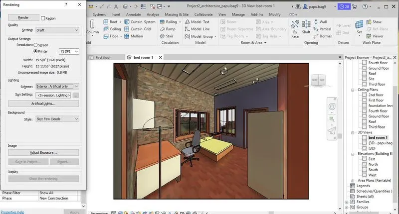
Step 2- After producing of the appropriate 3d model in camera view, the rendering of image can be done by using the render command i.e. RR, a pop up box will open where the required setting has been edit to produce good render image.
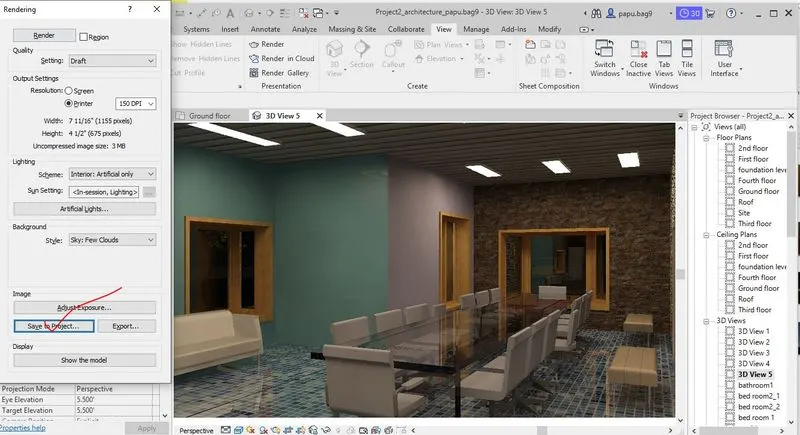
Step 3- after rendering of the image, the rendered image has been saved to the project.
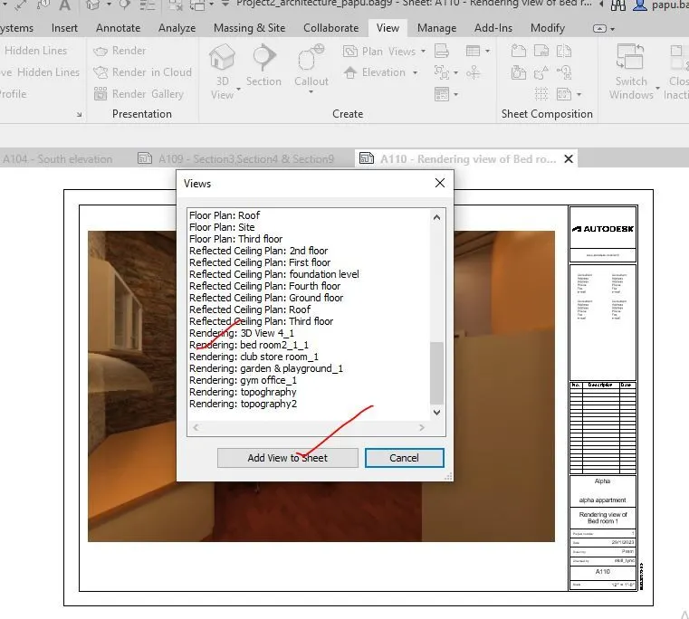
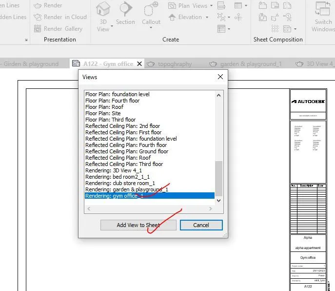
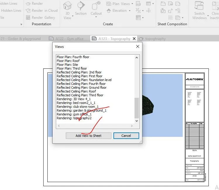
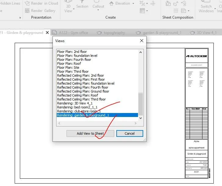
Step-4- then a sheet has been opened by using the sheet tool in the view tool. Here in this project, A1 metric size of sheet template has loaded. After selection of the size of the sheet, the of the sheet with project information has been edited to the sheet.
Here in this project the sheet has been used as name i.e. given below
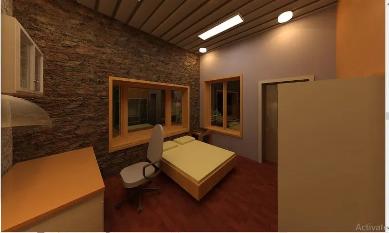
A110 Rendering view of Bed room 1
A111 Rendering of Bed room 2
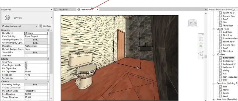
A112 Rendering of bathroom
A113 Rendering of dining
A114 Rendering of kitchen
A115 Rendering of living room
A116 Rendering of corridor
A117 Rendering of parking
A118 Rendering of front view
A119 Rendering of club meeting area
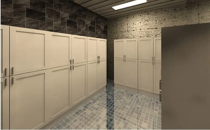
A120 Club store room
A121 Girden & playground
A122 Gym office
A123 Topography
For structural template,
S.6 Rendering of structure
S.7 Rendering of Structure 2
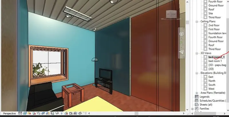
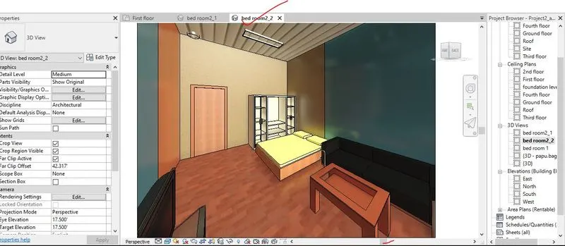
All the screen shots in producing the rendering images and placing the drawing in the respective sheet has been shown below,
6.3- Results-
All the results in using the Rendering settings, Render images of the 3D model produced and include the rendered images to the drawing sheets i.e. Rendering from interior rooms, rendering from out showing topographic features and Rendering through structural framing in REVIT is shown below,
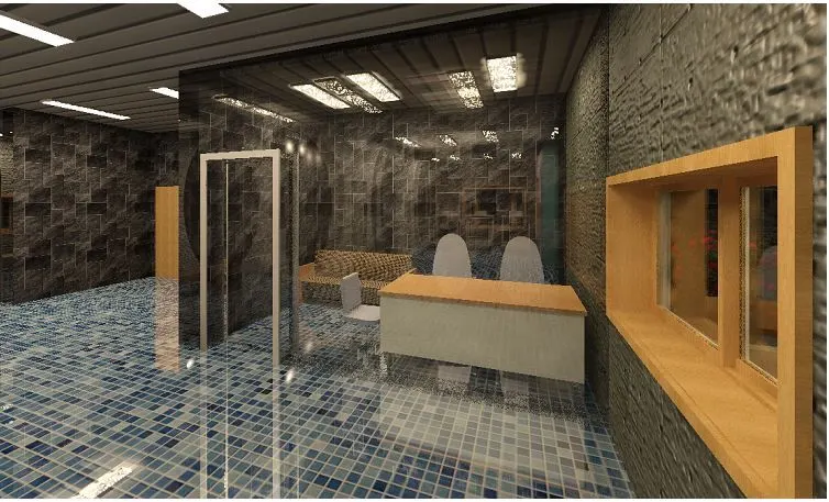
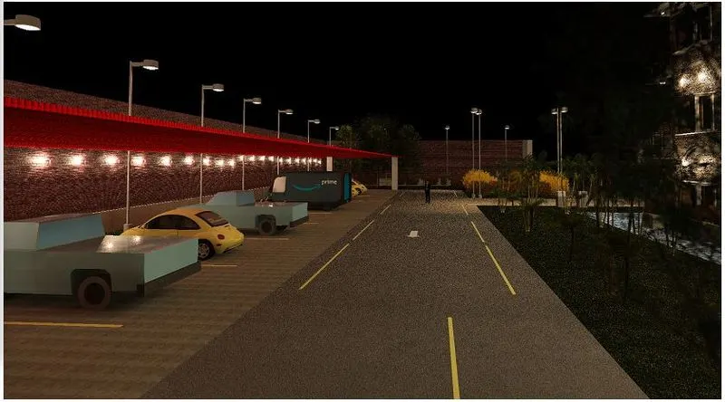
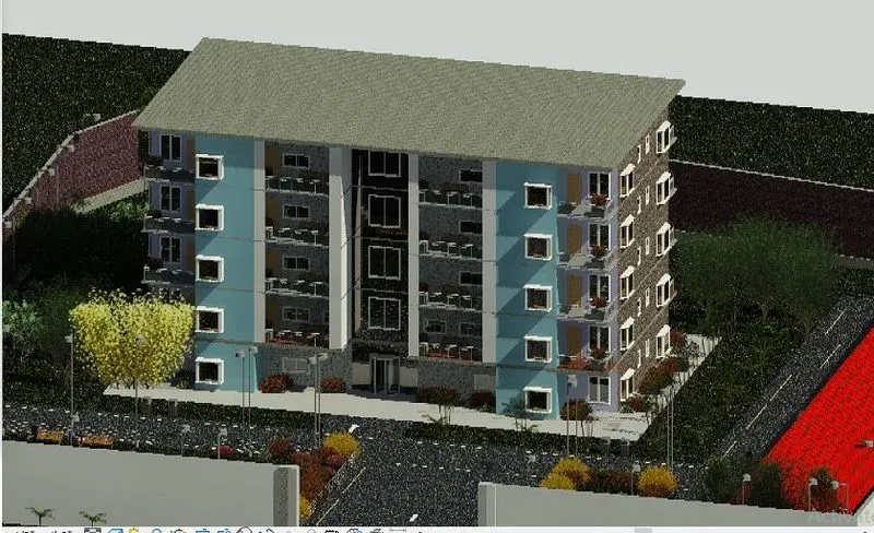
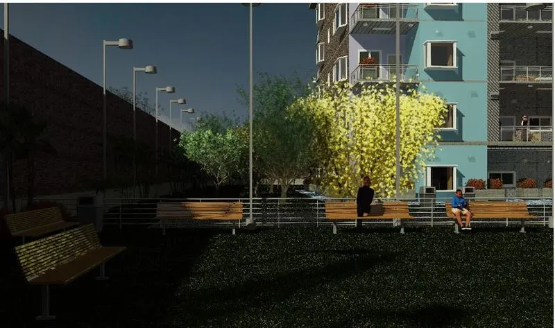
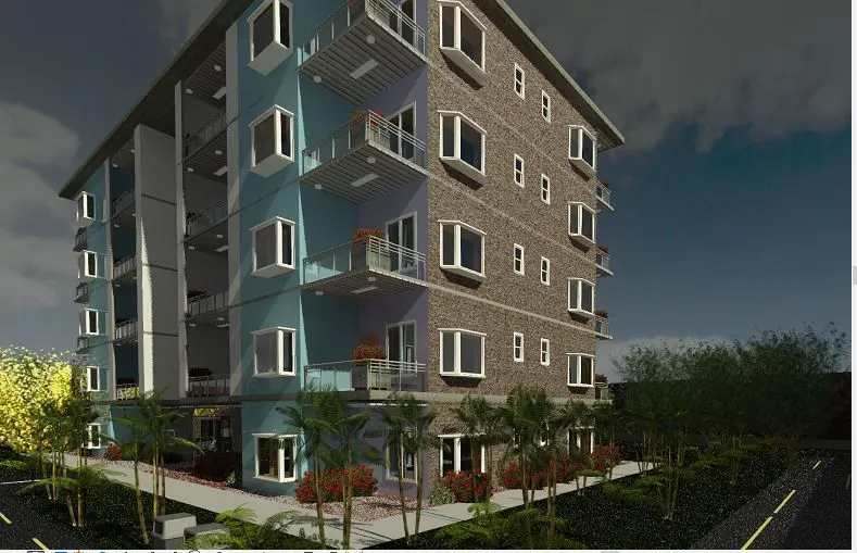
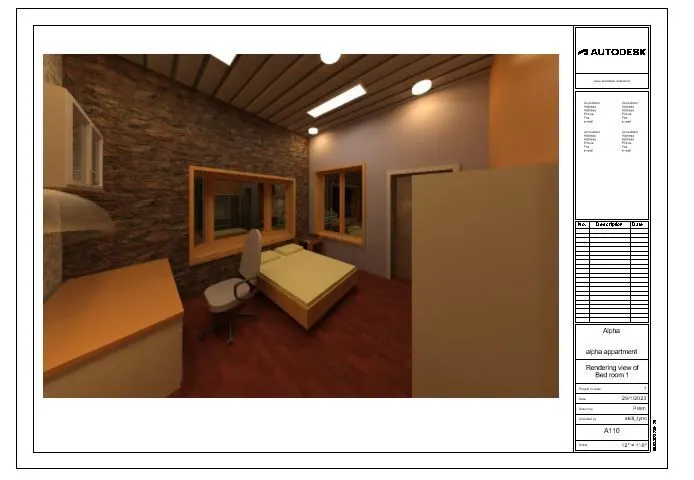
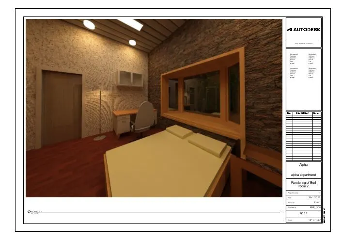
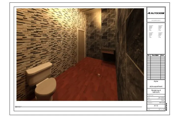
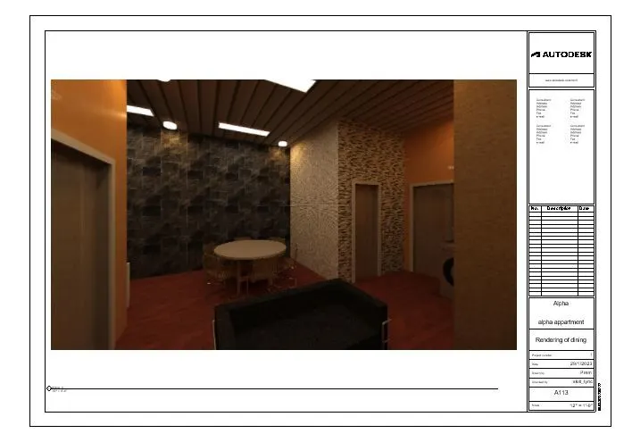
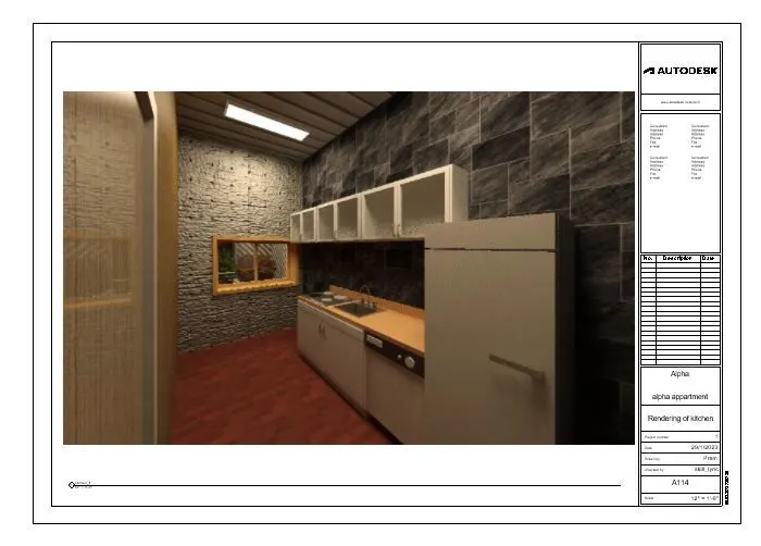
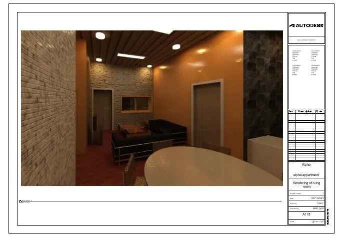
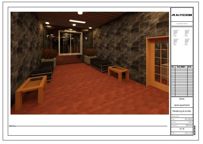
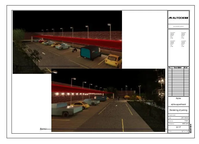
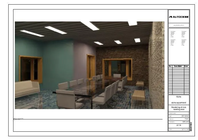
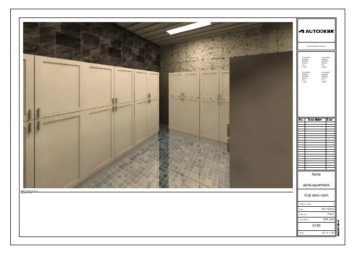
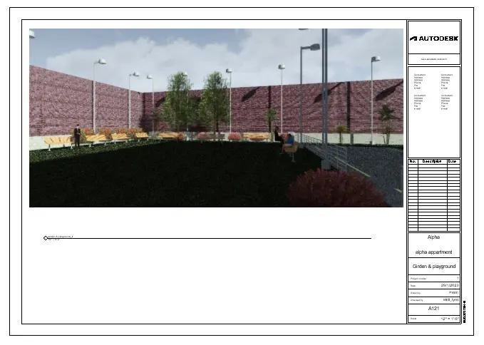
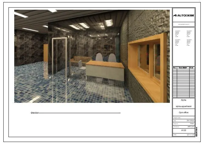
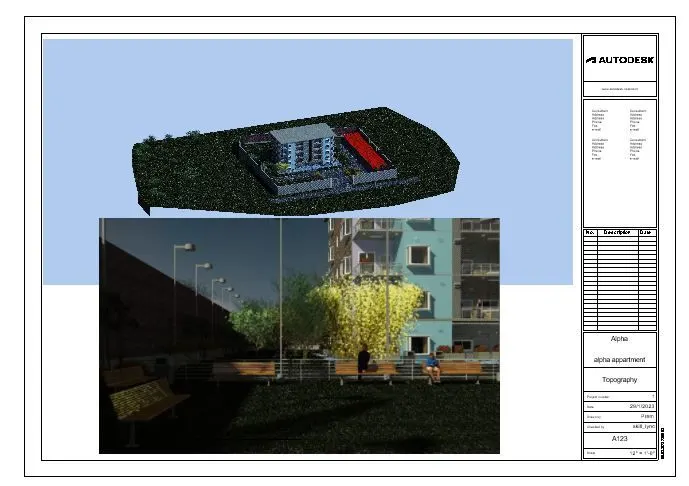
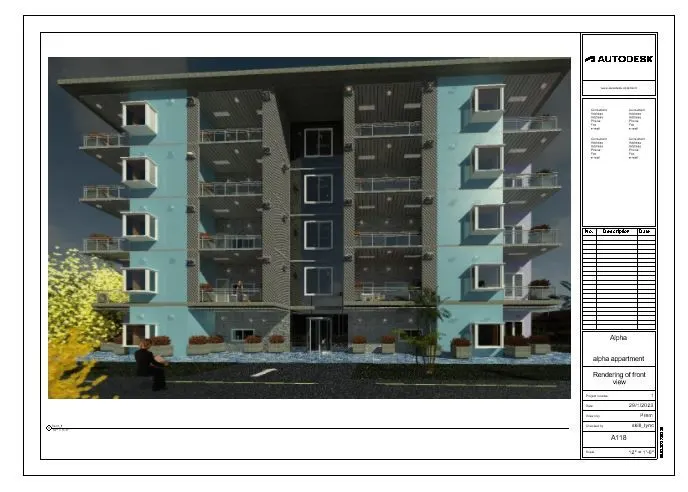
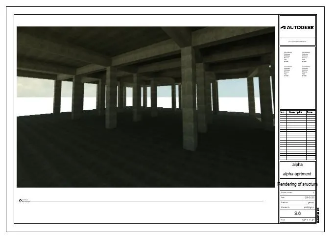
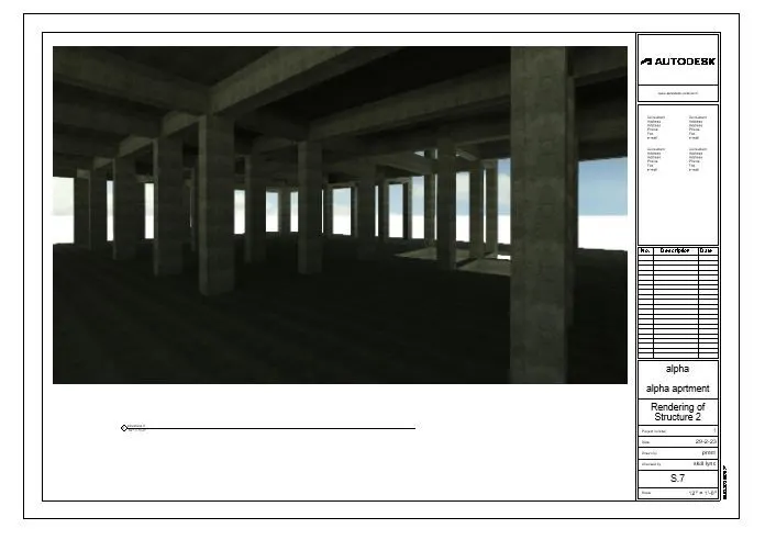
- The results of using the Rendering settings, Render images of the 3D model produced and include the rendered images to the drawing sheets i.e. Rendering from interior rooms, rendering from out showing topographic features and Rendering through structural framing in REVIT i.e. the .rvt file is uploaded named as 'Project2_architecture'.
----------------------------------------------------------------------------------------------------------------------
7) Print the set of drawing sheets created and submit the drawings from the architecture and structure model.
------------------------------------------------------------------------------------------------------------------------
7.1 Aim of the project- To print the set of drawing sheets created and submit the drawings from the architecture and structure model in Revit.
7.2 Procedure-
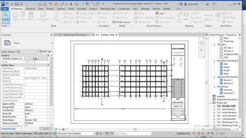
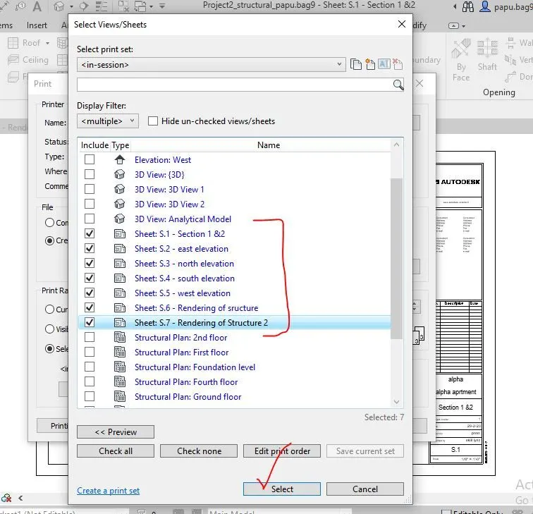
Step 1- To print the set of drawing sheets of different model like architectural and structural model, first the required sheet has to be opened by double clicking on the required sheet from project browse.
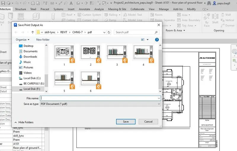
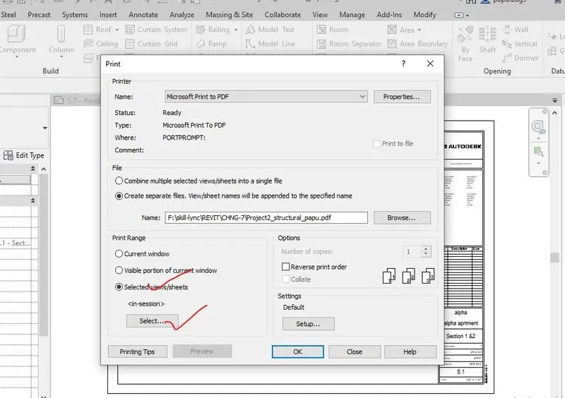
Step 2- after opening sheet from project browser, for printing the sheet by using the command ctrl+P, then a dialog box is opened where save as pdf option has been chosen to save the document with appropriate name.
All the screen shot in printing the set of drawing sheets created and submit the drawings from the architecture and structure model in Revit has been shown in below,
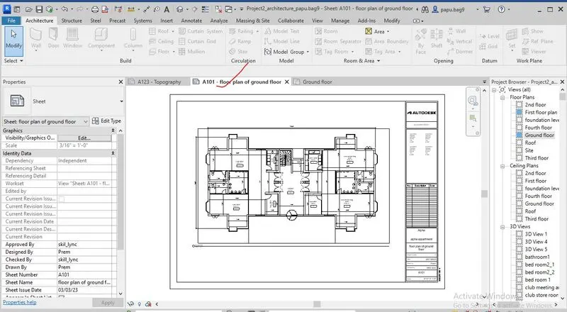
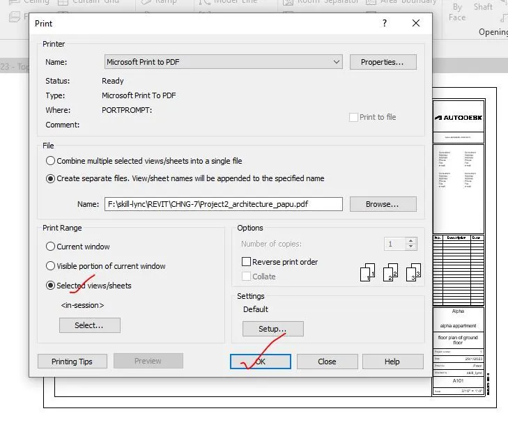
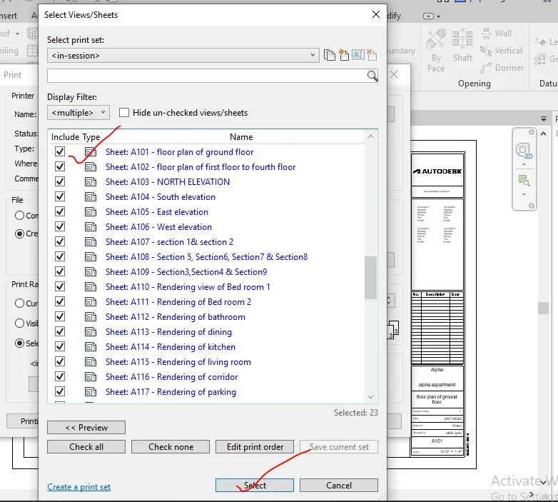
7.3 Results
- The results of printing the set of drawing sheets created and submit the drawings from the architecture and structure model in REVIT i.e. the .rvt file is uploaded named as 'Project2_architecture' and all the pdf formated sheeet documents named as
For architectural model
A101- floor plan of ground floor.pdf
A102- floor plan of first floor to fourth floor.pdf
A103- NORTH ELEVATION.pdf
A104-South elevation.pdf
A105-East elevation.pdf
A106-West elevation.pdf
A107-section 1& section 2.pdf
A108-Section 5, Section6, Section7 & Section8.pdf
A109-Section3, Section4 & Section9.pdf
A110 Rendering view of Bed room 1.pdf
A111 Rendering of Bed room 2.pdf
A112 Rendering of bathroom.pdf
A113 Rendering of dining.pdf
A114 Rendering of kitchen.pdf
A115 Rendering of living room.pdf
A116 Rendering of corridor.pdf
A117 Rendering of parking.pdf
A118 Rendering of front view.pdf
A119 Rendering of club meeting area.pdf
A120 Club store room.pdf
A121 Garden & playground.pdf
A122 Gym office.pdf
A123 Topography.pdf
For structural model
S.1-Section 1 &2.pdf
S.2-east elevation.pdf
S.3-north elevation.pdf
S.4-south elevation.pdf
S.5-west elevation.pdf
S.6 Rendering of structure.pdf
S.7 Rendering of Structure 2.pdf