Project 2_Creating a 3D rendered model for a Residential Building in AutoCad
- Aim and introduction
1.1 Aim of the challenge:-To create a 3 dimensional model of the residential building with a rendered view.
1.2 Introduction:-
3D modelling in AUTOCAD is the details representation of any type of objects or any surfaces which provides the level of modelling depth and improve the control over the details of the material or objects. This helps in exploring the physical aspect of any design without surrendering the physical parameters.
In AUTOCAD 3d modelling, there are 10 numbers of visual styles which helps in demonstrating the detail view of any objects. Lists of the visual styles has been given bellows,
- 2D wireframe
- Conceptual
- Hidden
- Realistic
- Shaded
- Shaded with edges
- Shades of grey
- Sketchy
- Wireframe
- X-ray
In 3D modelling AUTOCAD, here we can be rendering the model into a realistic image which include basics lightning and more sophisticated that stimulate shadows, reflection and refraction by using the material details s of the required objects which can give the realistic view to the any kind of objects in the 3D rendering process.
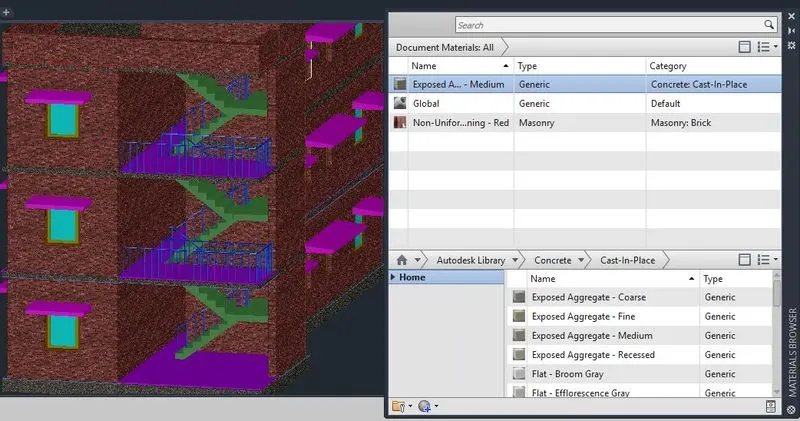
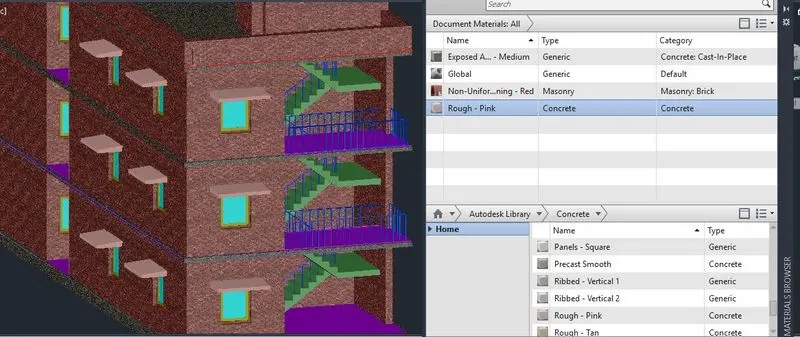
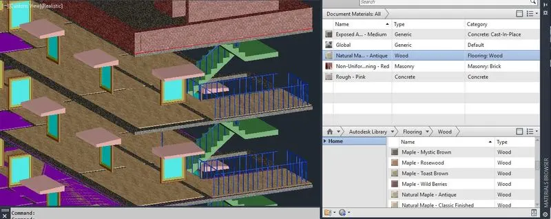
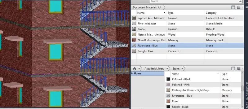
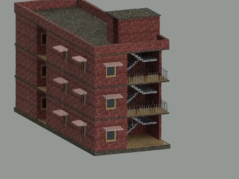
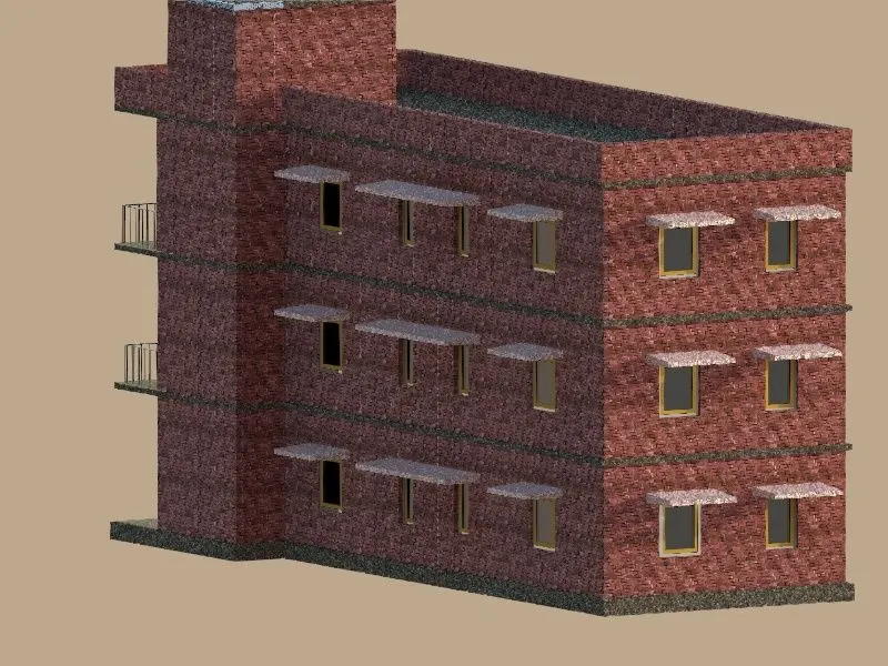
Here in the residential projects, the materials used for brickwork is non-uniform running- red, for concrete floor, it is exposed aggregate medium, generic type, for floor finishing, it is natural maple antique which is wood type, for stair, it is riverstone blue which is stone type, for railing, stainless steel- bright, for glass it is blue reflective and for sunshade work, the concrete is used rough pink.
In the architectural plan, there are some objects like external wall, internal wall, window, stairs, doors, cup-boards and rooms for example bed room, toilets, dining and living rooms has to show with required size and dimension and structural drawing shows the column, beam layout and footing layout in which the details of the location of the all the beams and columns with their sizes and the footing location also.
Information for the plan and 3D modelling of the residential building,
- Here the size of the plot size is 3m ×6m
- Facing of the building is east facing.
- Size of the doors are 2000mm × 650mm, 2000mm × 800mm and 2000mm ×720mm.
- Size of the windows are 1200mm×1000mm
- Sill height of the building is 800mm,
- Lintel height of the building is 2000mm,
- Size of the external wall is 230mm and internal wall of size 150mm,
- Slab width of 125mm,
- 25mm of the flooring finishing i.e. natural maple antique type wood.
- Height of the floor is 2850mm.
- Riser and tread of the staircases are 151.39mm and 150mm respectively.
- Railing with material of aluminium polished metal having height of 800mm.
- Parapet wall of the height of 1000mm having material specification of the brickwork of non-uniform running- red.
1.2.1 Commands used in modelling 3 dimensional residential building
- ‘UN’ for units
- ‘LIMITS’ for specify the limit of the sheet.
- ‘L’ (for line)
- ‘PL’ (for poly line)
- ‘O’ for offset
- ‘LA’ for layer
- ‘LAYON’ AND LAYOFF’ layer on and off.
- ‘MI’ for mirroring the object
- ‘RO” for rotating the object
- “CO” for copy
- “XL” for construction line
- ‘TR’ for trimming the object
- ‘F’ for filleting
- ‘C’ for circle
- ‘ARC’ for arch of circle
- ‘REC’ to draw rectangle
- ‘J’ to join
- ‘DIM ‘for dimension, DIMLIN (for linear dimension), DIMBREAK, DIMCONTINUE, DIMBASE
- ‘DDIM’ for dimension style manager
- MT for multi text
- ‘ED’ (for edit text)
- ‘B’ (for creation of the block)
- ‘I” (for insertion of the block)
- ‘SC’ (to scale the objects)
- ‘H’ (for hatching)
- ‘EXT’ for extrude
- ‘REG’ for region
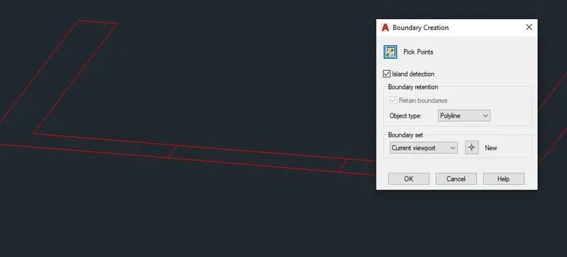
- ‘BO’ for making the boundary.
- ‘UCS’ for the appropriate place for coordinate system.
- ‘SWEEP’ for sweep of the object.
- ‘CYLINDER’ for making the 3d object cylinder.
- ‘3D face’ for the making the 2d object into 3d surface.
- ‘3DRO’ for rotate the 3d object.
- ‘3DMI’ for mirror the 3D object.
- ‘SL’ for slicing the object.
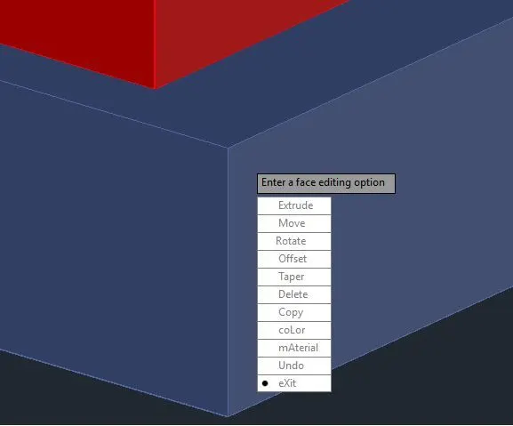
- ‘SOLIDEDIT’ for editing of the solid.
- ‘3DO’ for 3D orbit.
- ‘METERIALS’ for material browsing.
- ‘RR’ for rendering.
- ‘EXPLODE’ for explode the object.
- ‘SUB’ for subtract the object from the existing object.
- ‘UNI’ for union.
- ‘QSAVE’ for quick save.
1.3 Procedures to Sketch the plan of a residence building.
1.3.1 Procedure to sketch the floor plan of the residential building
- After starting the AUTOCAD, the unit and limits should be specified.
- As per our requirement, the unit has been taken in Engineering and, metric unit. So to select unit, UN command is used to select the units as engineering and the angle as decimal degrees and limits has been specified as <0,0> to <60000,66000>.
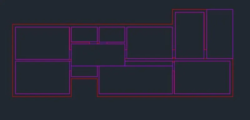
- Now by using the line command or also by using the XL command i.e. construction line the plot area of 18300 mm *6000mm. And the with help of offset command the wall of size 230mm and internal wall of 150mm. Then clear space of the room is constructed by using the trim tools.
- Two bed rooms of size 4500×2695, two toilets of size 2150×1250, kitchen of 4640×2695, drawing room of 3800×2615, living room of size 6100×2695, all the dimension is mentioned with the help of DIMLINEAR tools.
- Next to draw the stair cases of tread of size of 250mm with the help of the offset tools and by using the leader tool, the direction of the steps i.e. UP in stairs is showed.
- By using the circle, rectangle and line command, the door and window is done.
- After completion of all the necessary item like walls, doors and windows and staircase, to demonstrate or to mention the type of rooms like bed rooms, kitchen, toilets, living room and drawing room, the MT command is used to mention the name of the rooms with their sizes.
- Next to draw the furniture, the block tool is used to draw all the necessary block and with the help of the I command i.e. insertion of the blocks as per our requirement blocks have been inserted and scale to their required size. And also with the help of design centre some of them are inserted.
- Next the section line with the centre line style has been drawn and the chhaza also with dash line.
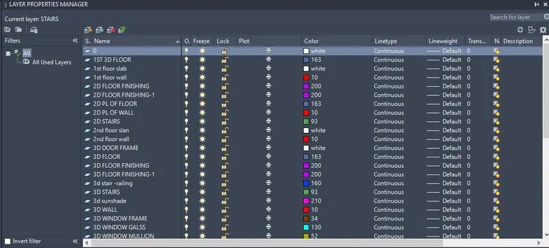
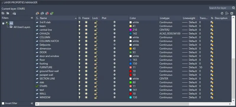
- To specified or to differentiate the all the item, different layer is made with different colours.
1.3.2 Step wise screenshots in drafting the plan of the residential building

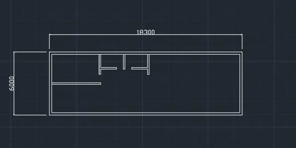
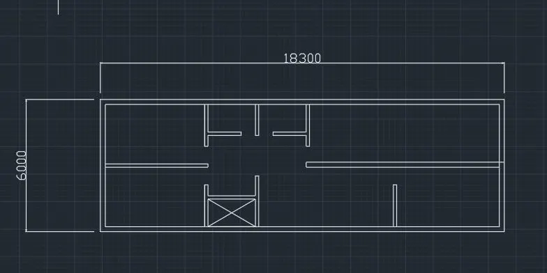
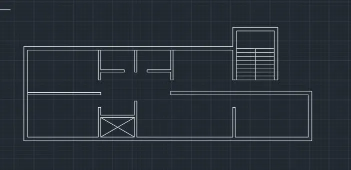
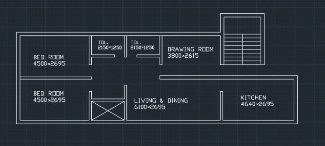
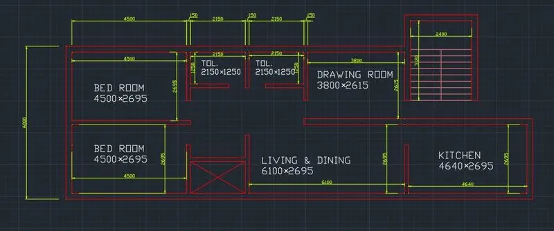
1.3.3 Procedure in modelling in 3D of the residential building according to the plan
- First of all, the drafting workplace should be changed to 3D modelling.
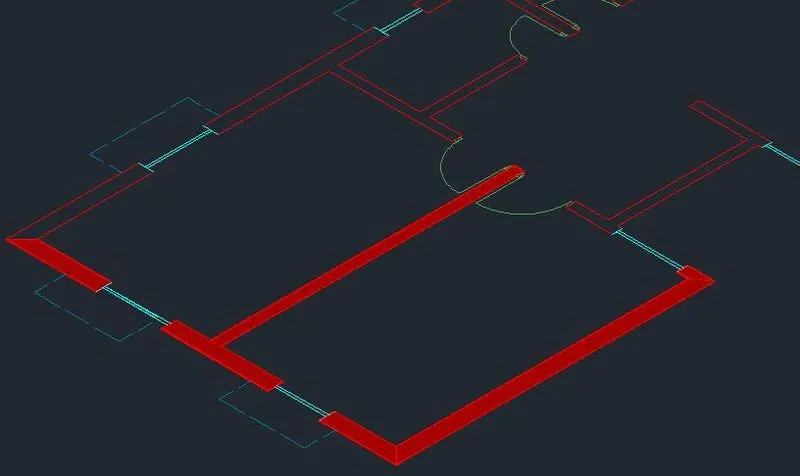
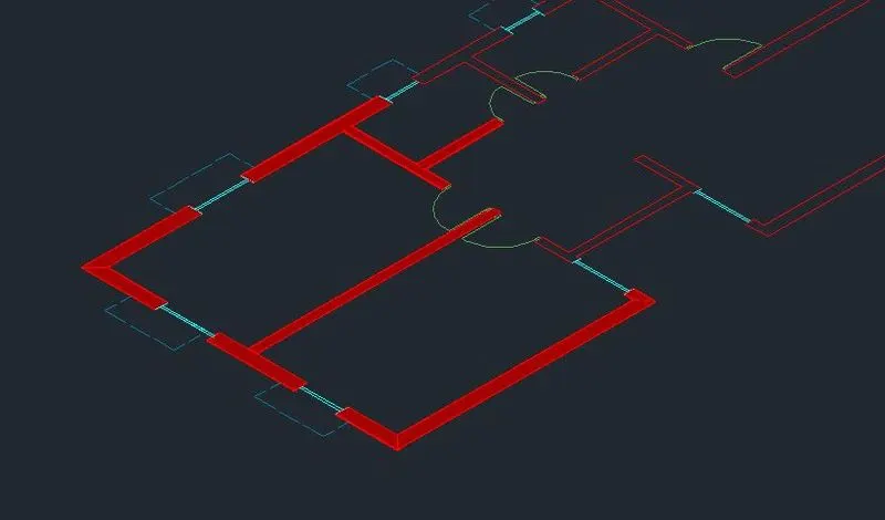
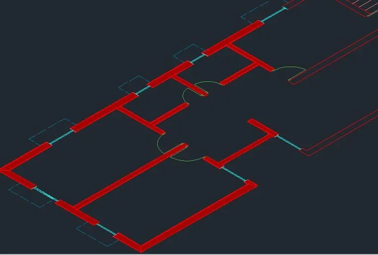
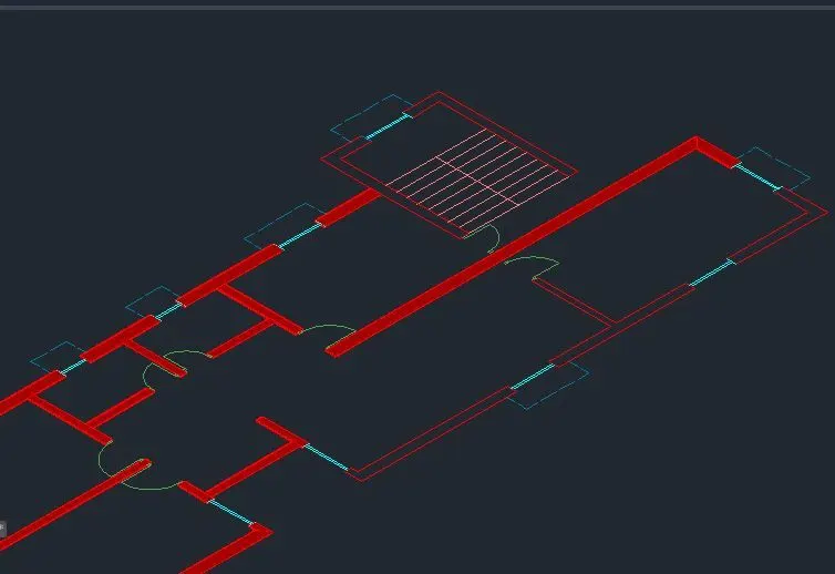
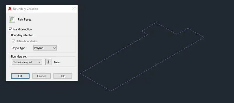
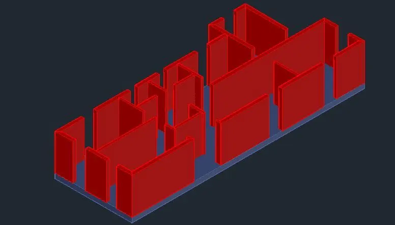
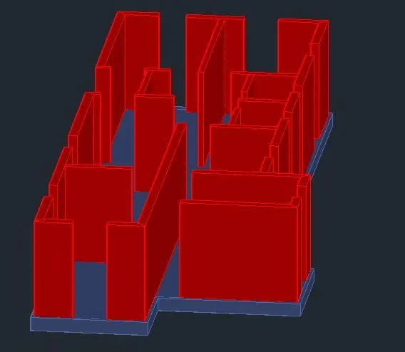
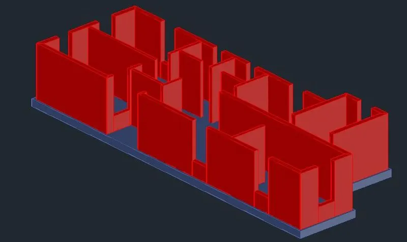
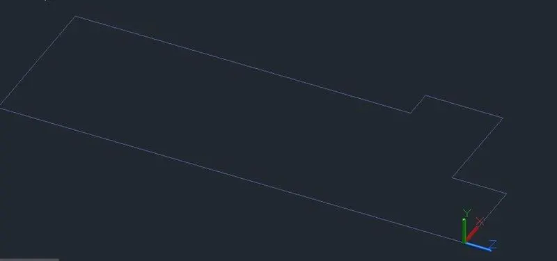
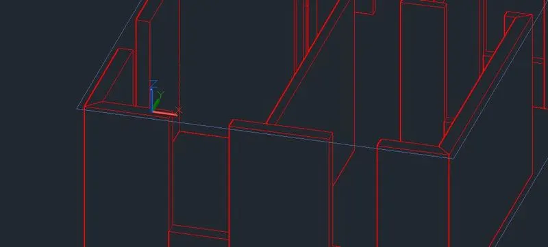
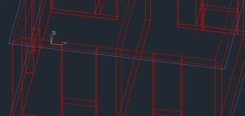
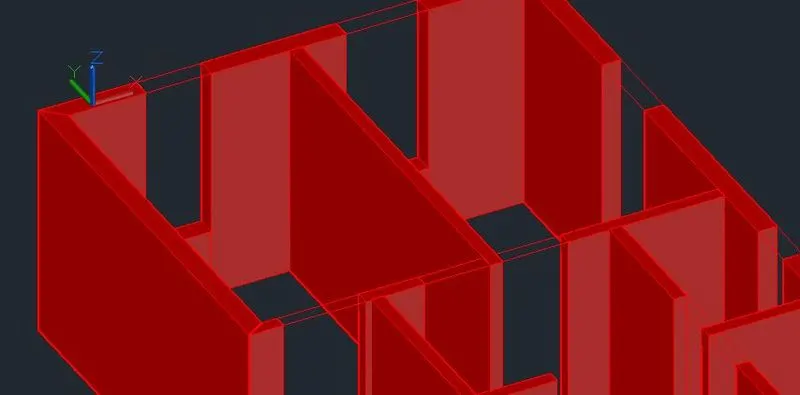
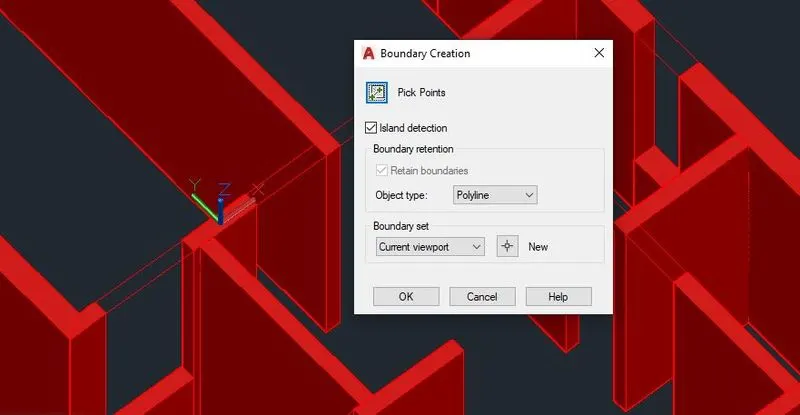
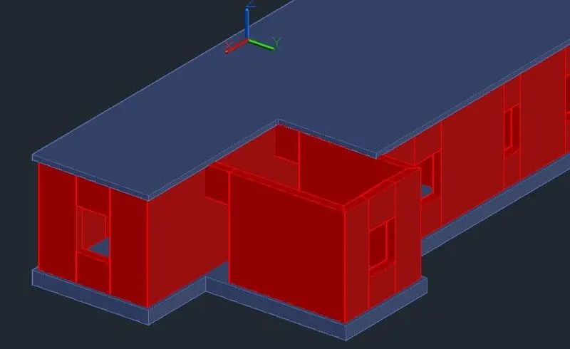
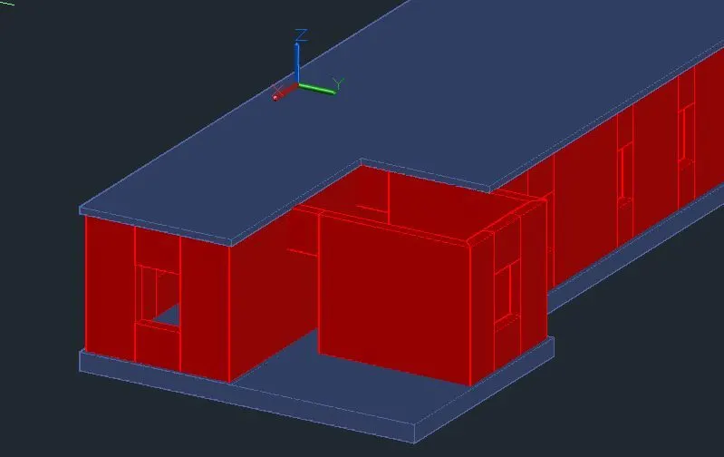
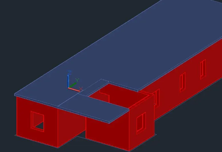
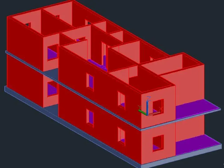
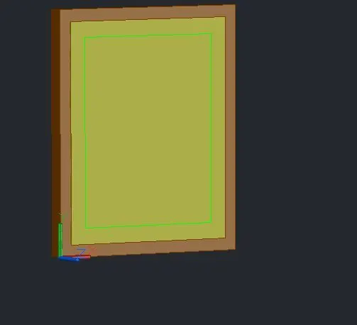
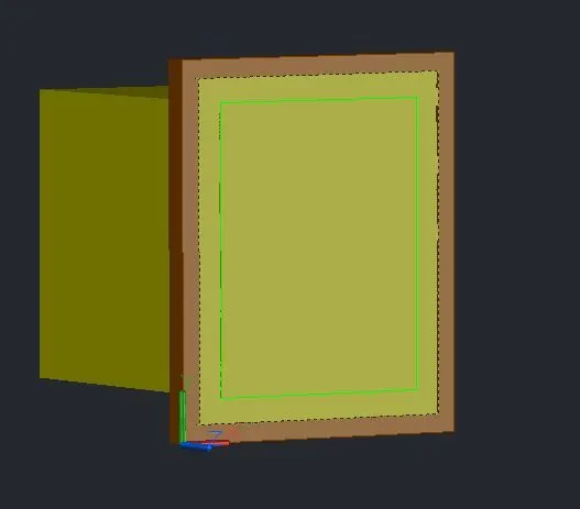
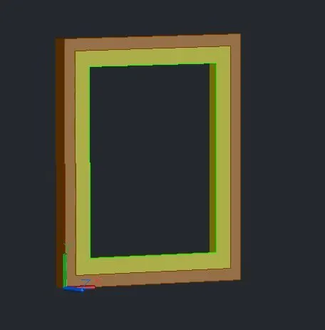
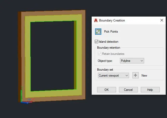
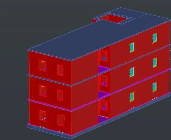
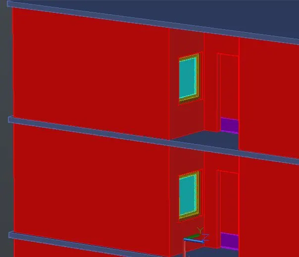
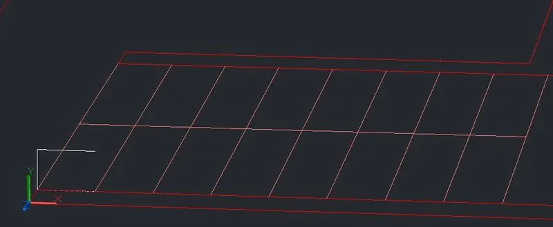
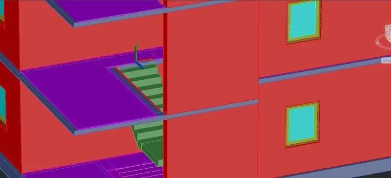
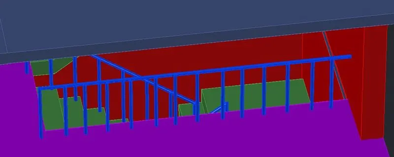
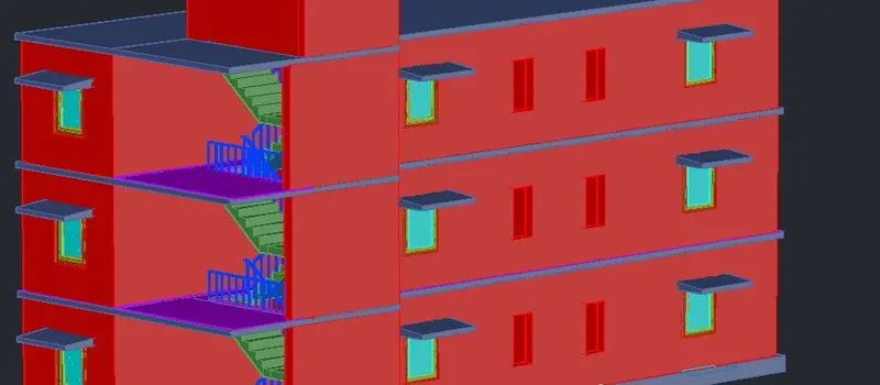
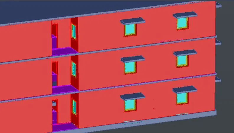
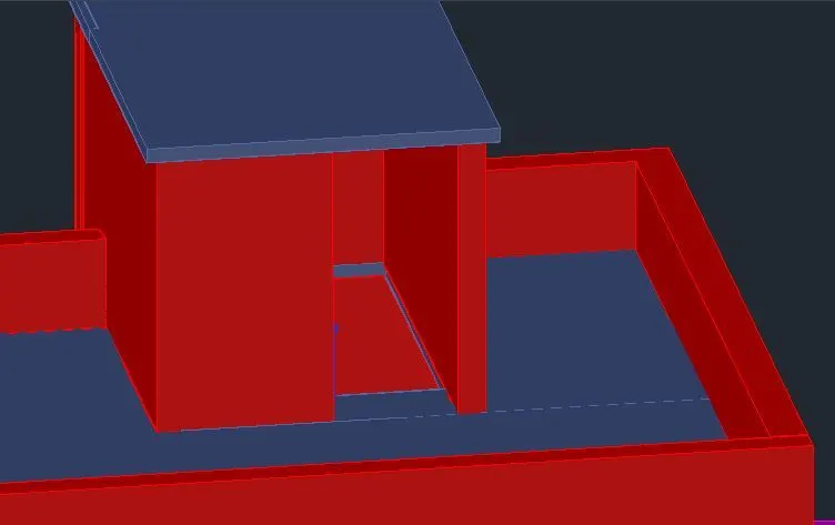
- As per the plan, the 2d wireframe of the wall is changed into the 3D surface by using the 3D face command, by making the region and making the boundary.
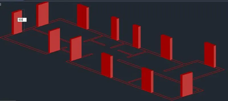
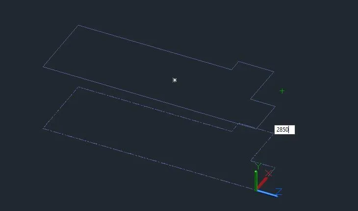
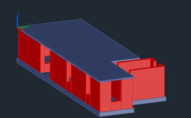
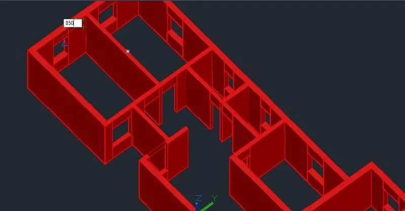
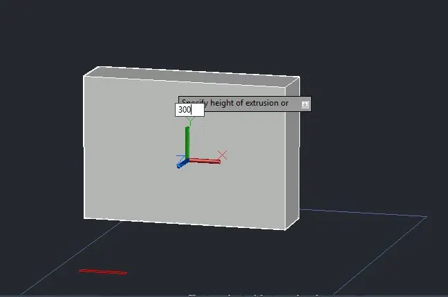
- After making the 3D surface, the 2d wall is to extrude a height of 2850mm in z-axis with layer of the 3D wall.
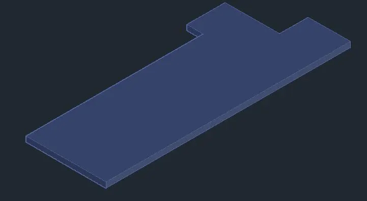
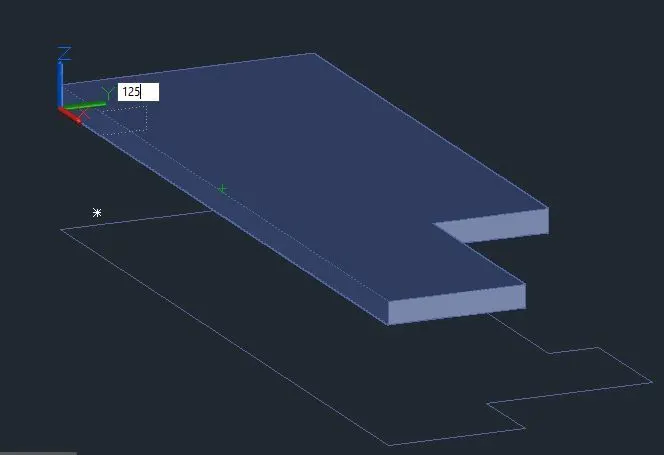
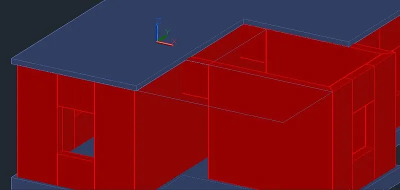
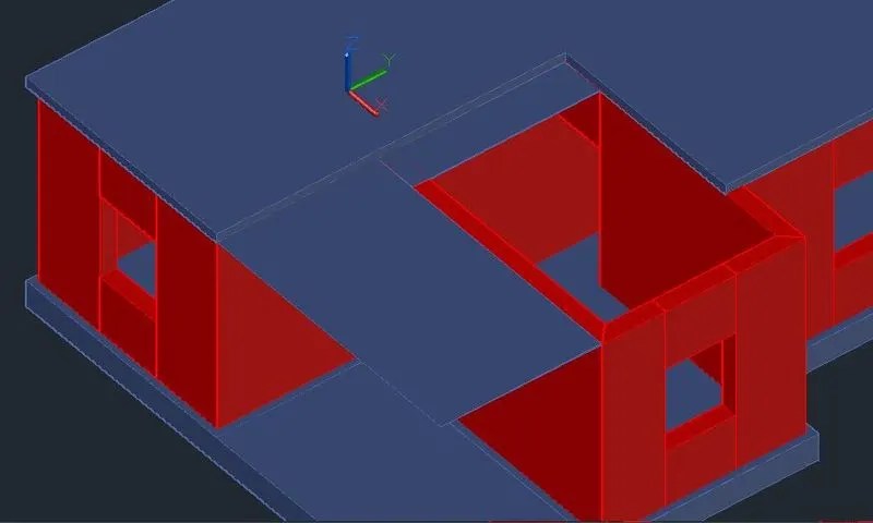
- Then, the 2D floor is to drawn according to the plan, and by using the region command, this 2D surface is changed into a 3D surface.
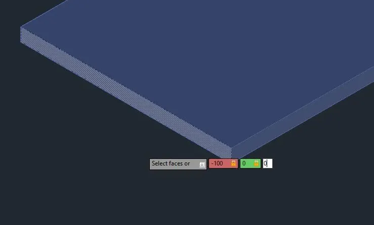
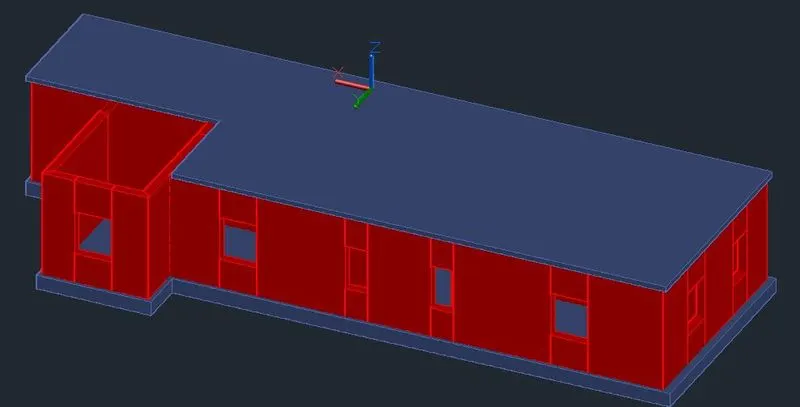
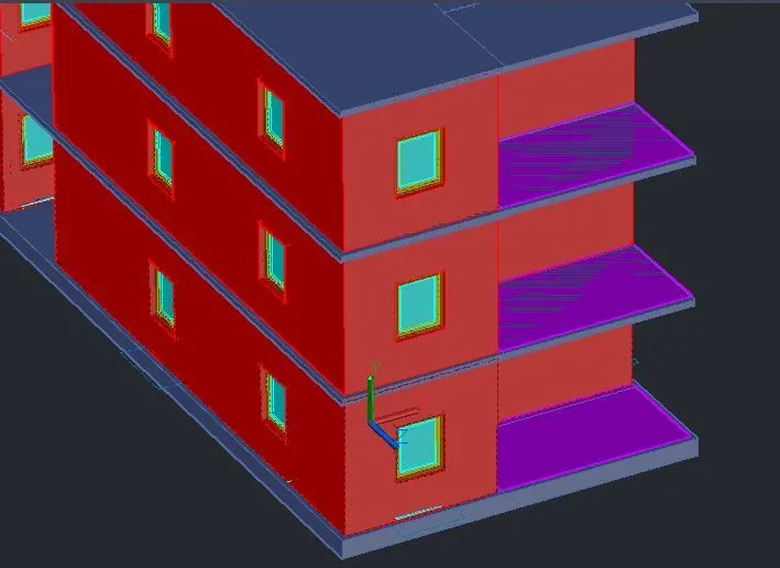
- 2D floor is extruded to a height of 125mm with different layer of 3D floor.
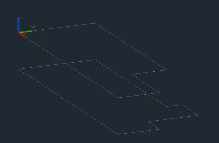
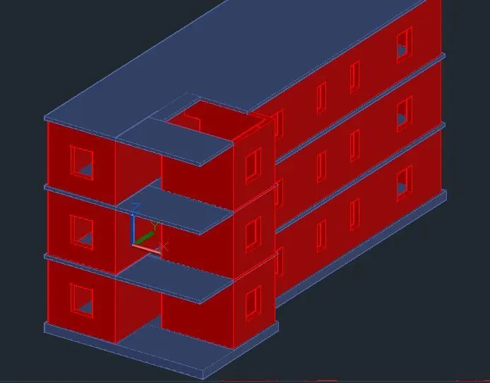
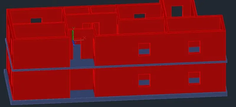
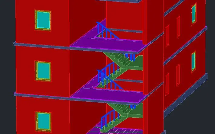
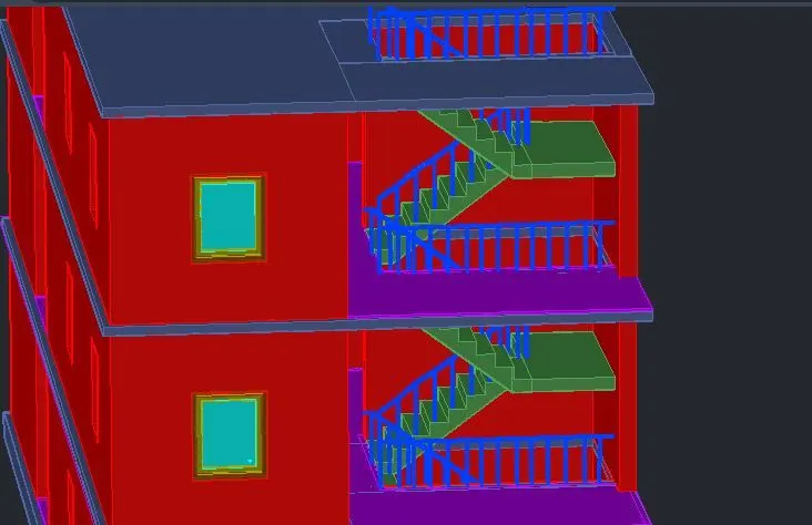
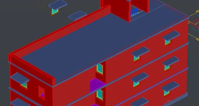
- Then, the 3D walls and 3D floor has been copied for 1st floor and 2nd floor with same plan.
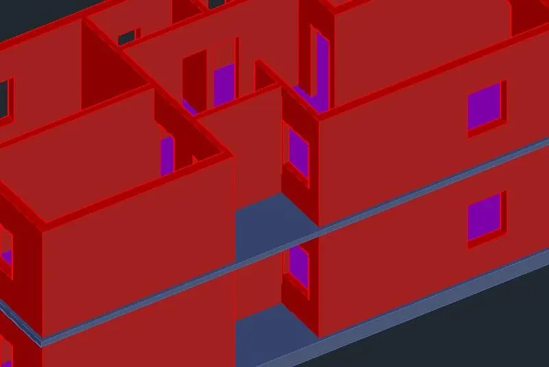
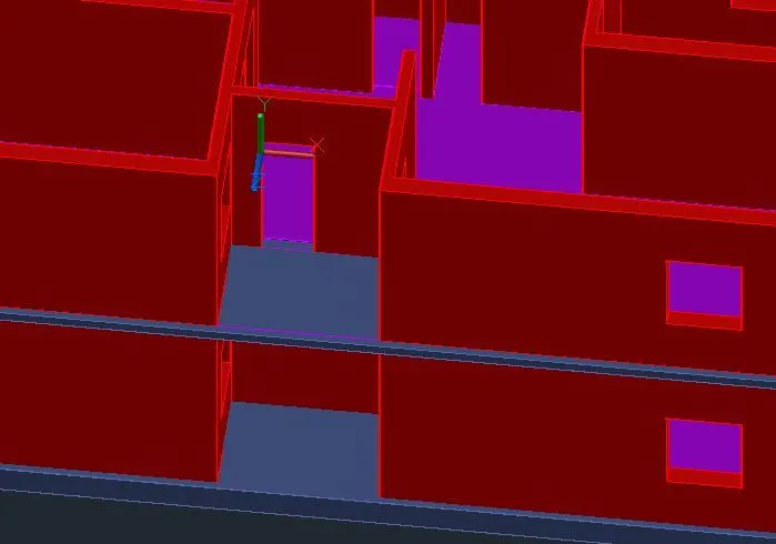
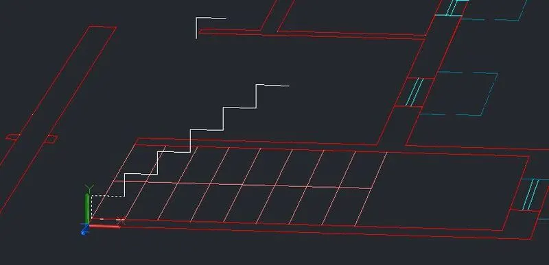
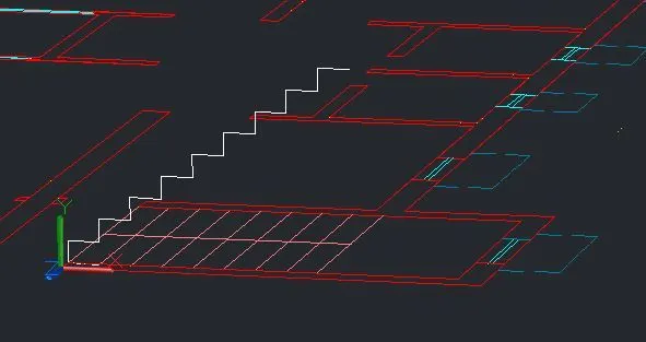
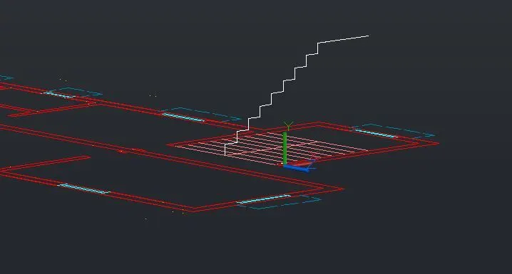
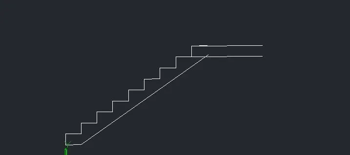
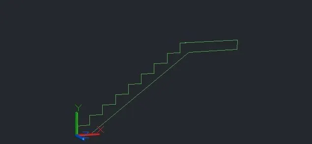
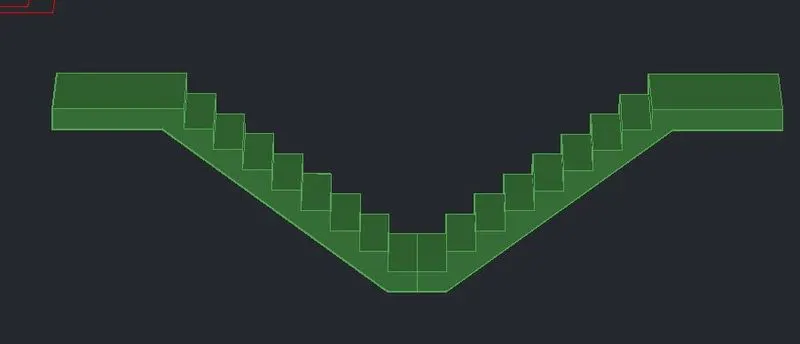
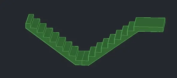
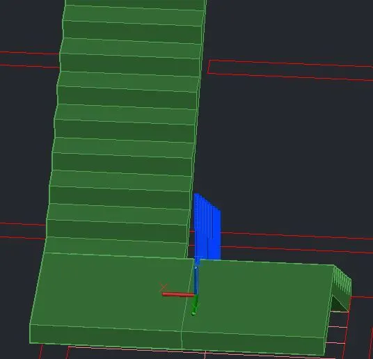
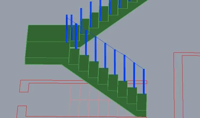
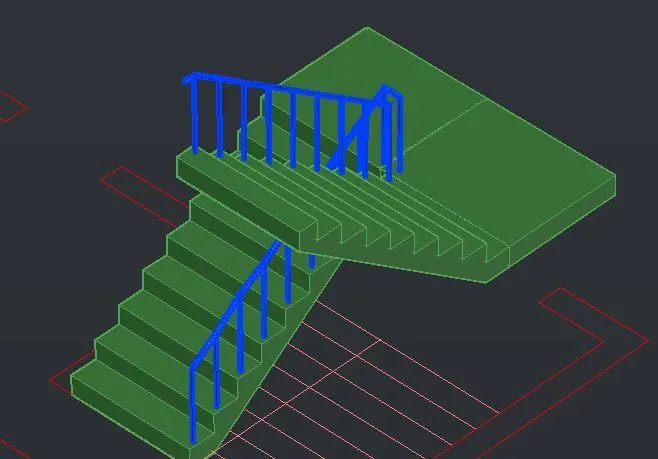
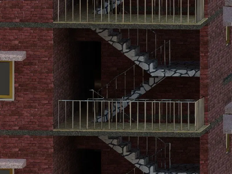
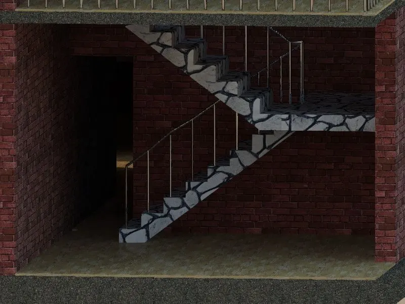
- The 2D stair has been drawn with appropriate UCS with 250mm of tread and 151.39mm of riser.
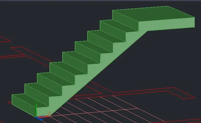
- By making the 2D stair into a 3d surface, it is extruded to width as per plan in y axis.
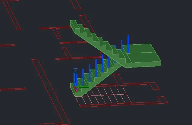
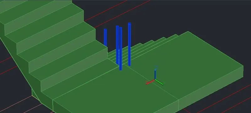
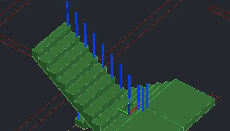
- The railing has been using the circle command which is then converted to a 3D surface, which is then extrude into height of 800mm.
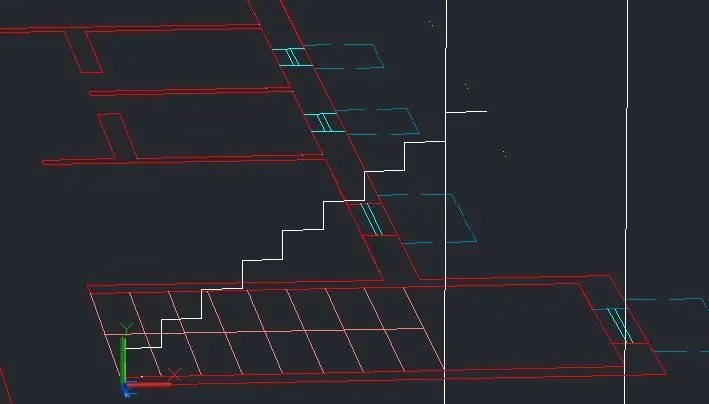
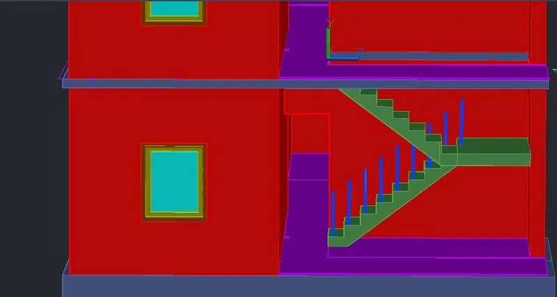
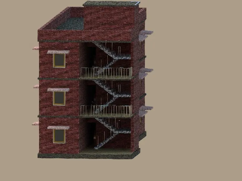
- After making of the stair with railing, it is then moved to the appropriate place by using move command which is then copied to 1st and 2nd
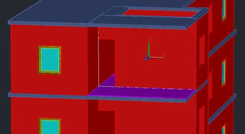
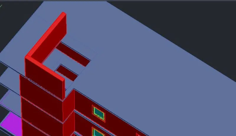
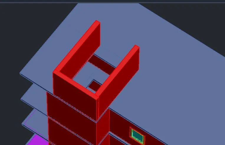
- By making the rectangle of size of parapet wall, which is then converted into a 3D surface, which is then extruded to a height of 1000m.
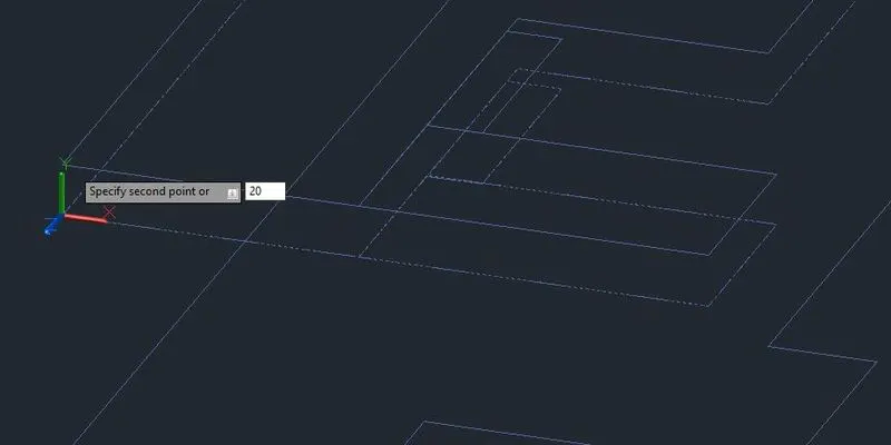
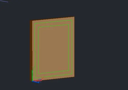
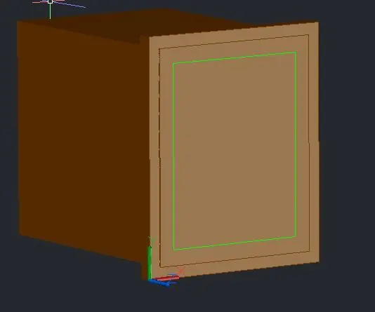
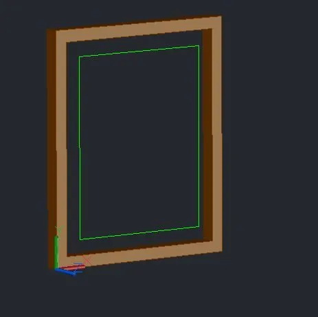
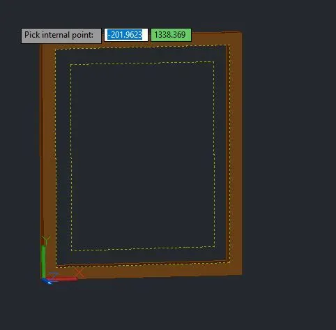
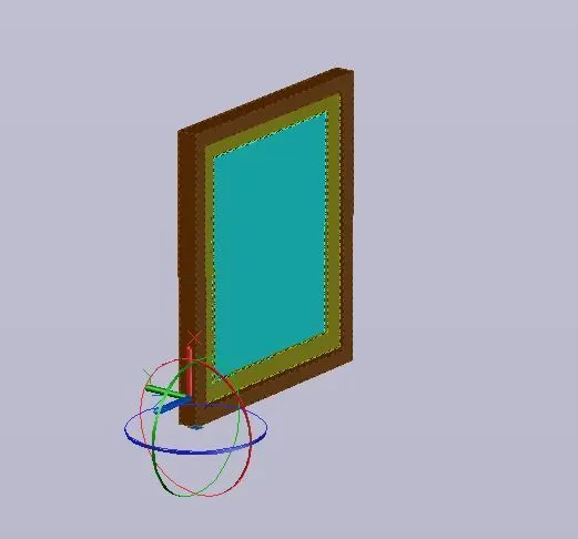
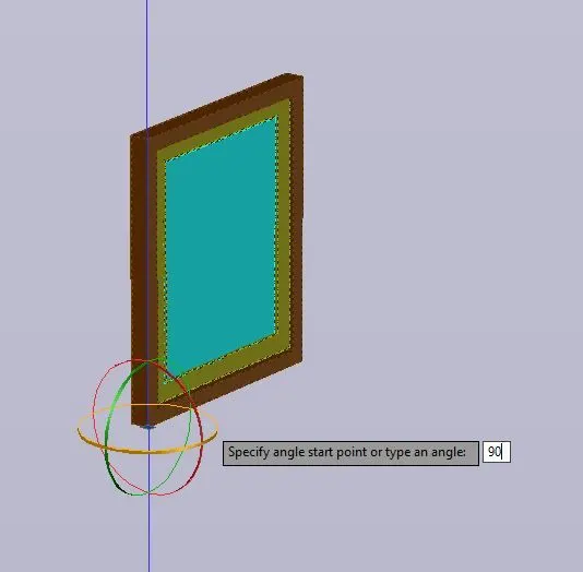
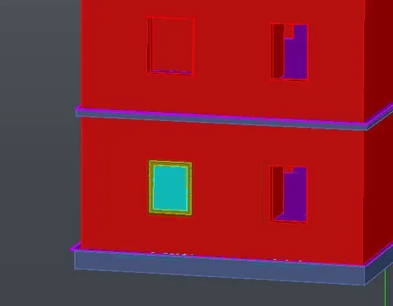
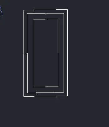
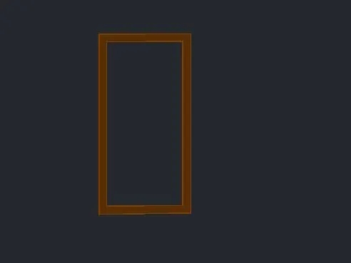
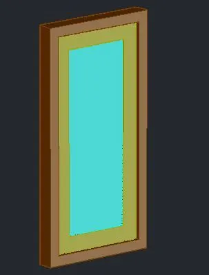
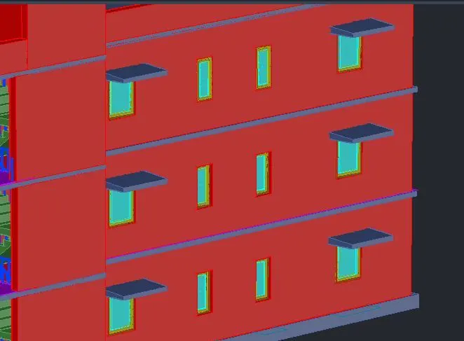
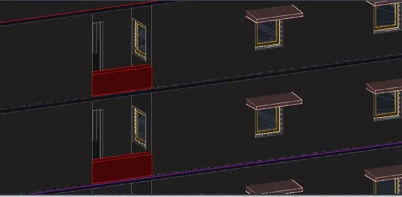
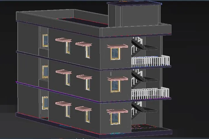
1.3.4 Step wise screenshots in modelling the 3 dimensional of the residential building
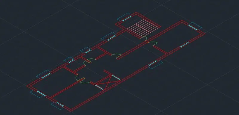
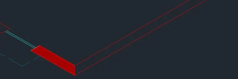
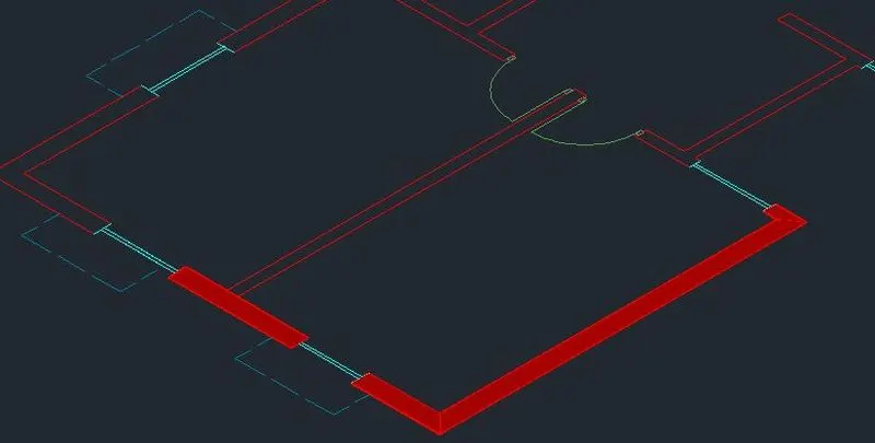
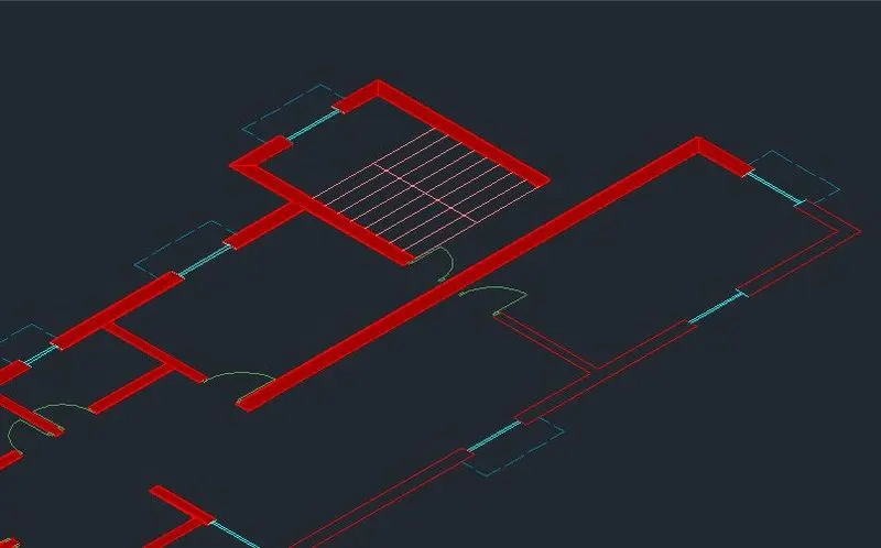
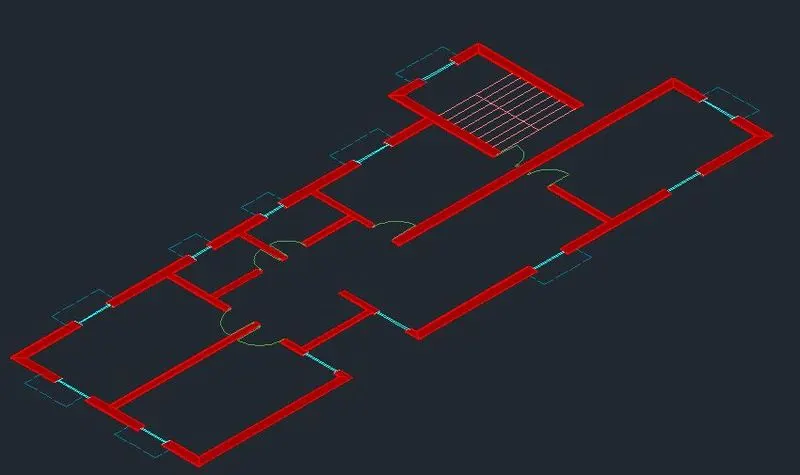

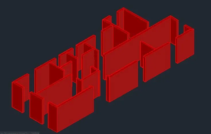
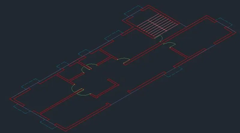

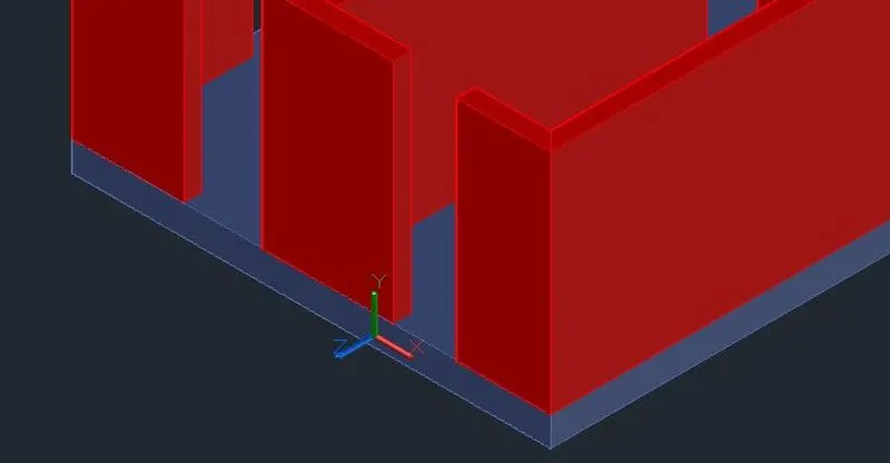
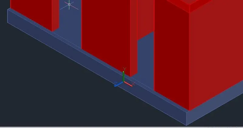
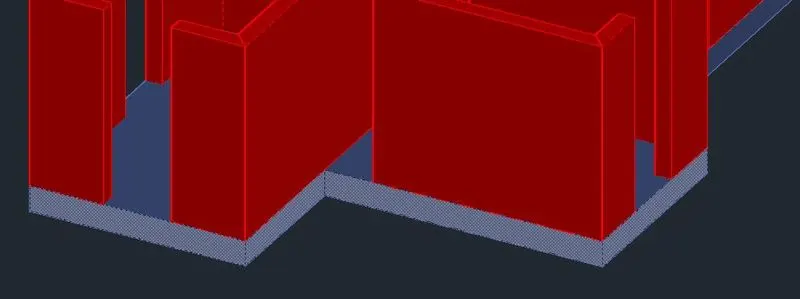
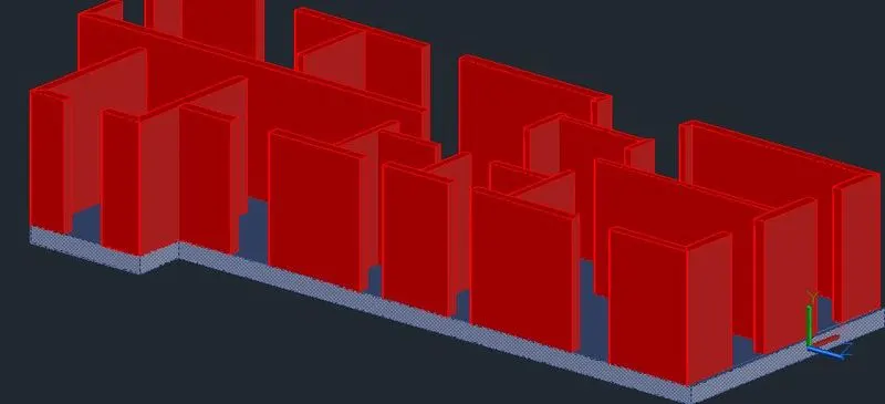

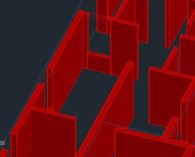
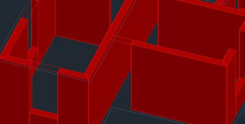
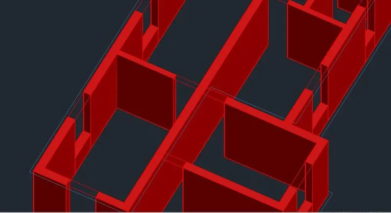
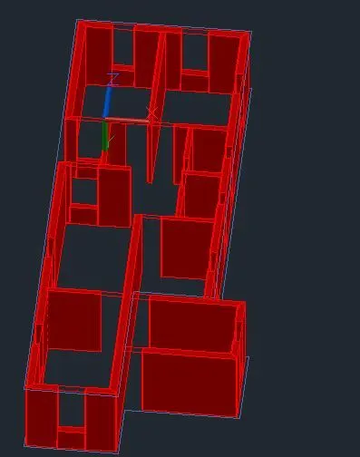
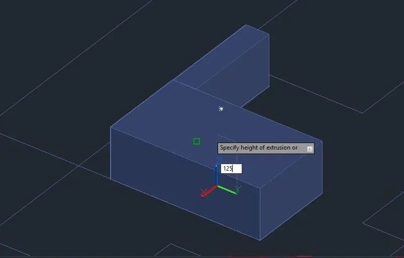
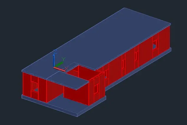
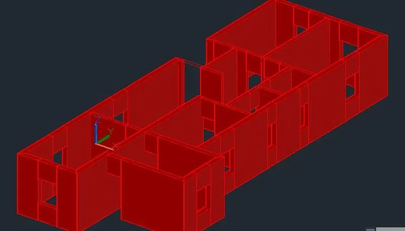
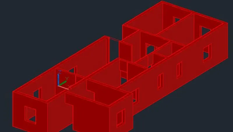
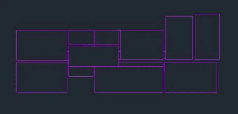
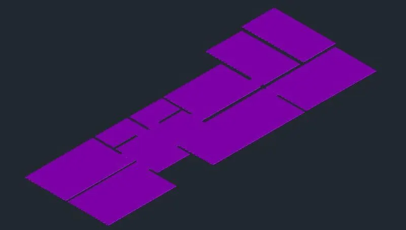
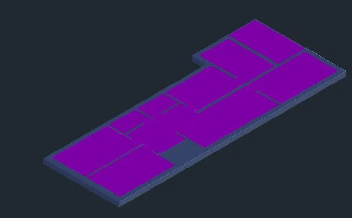
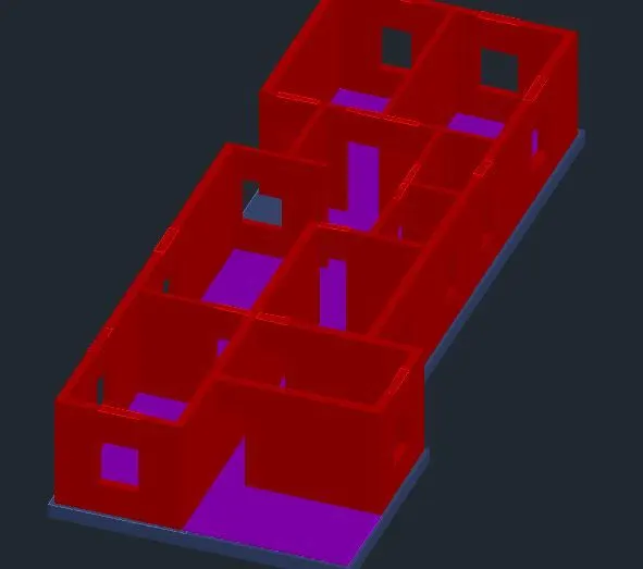
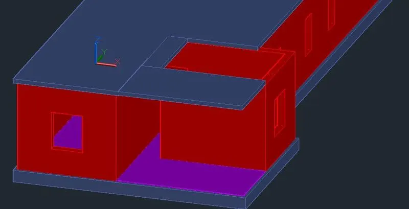
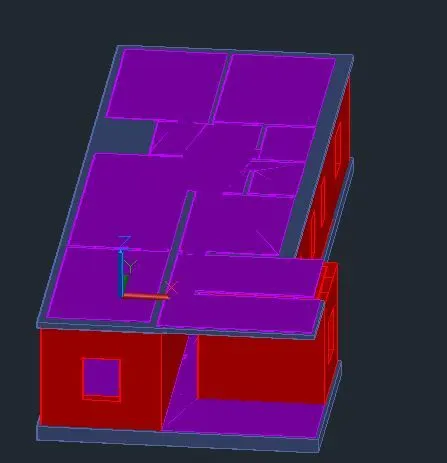
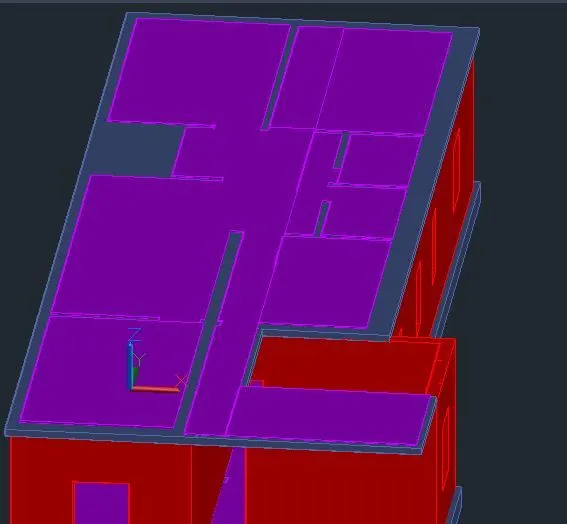
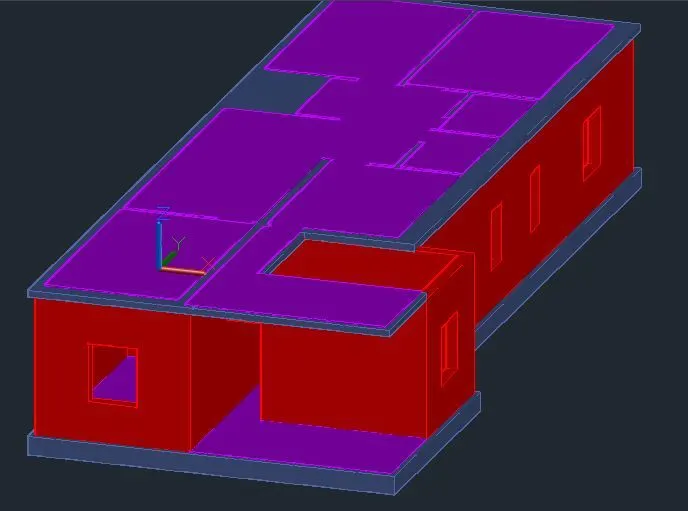
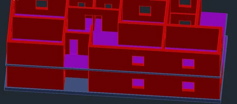
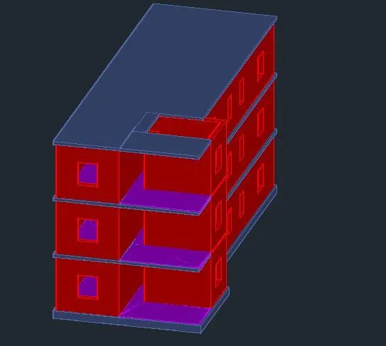
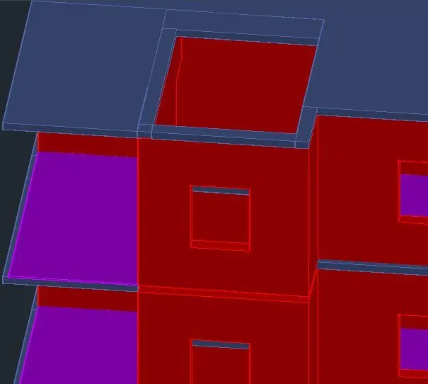
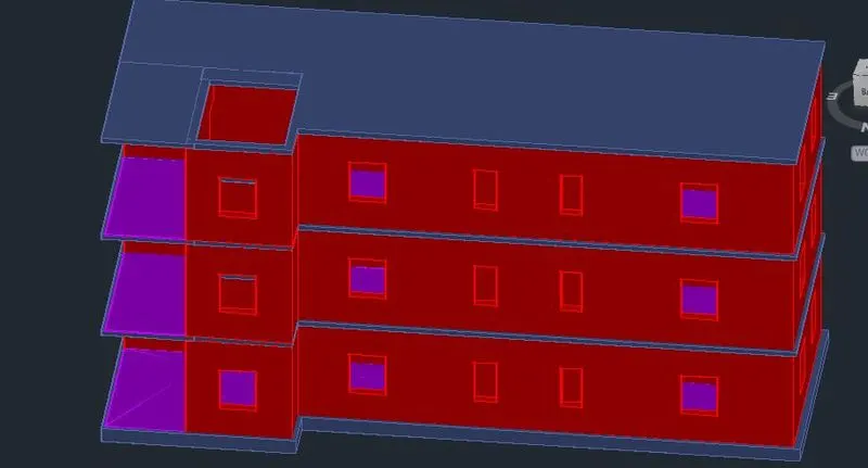
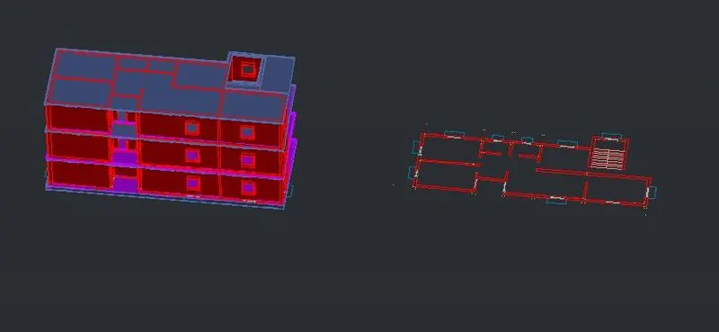
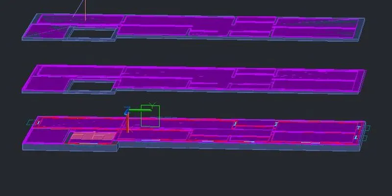
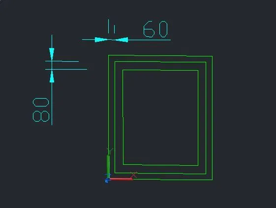
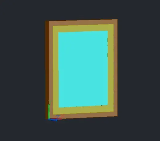

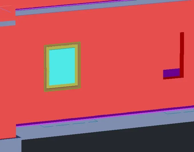

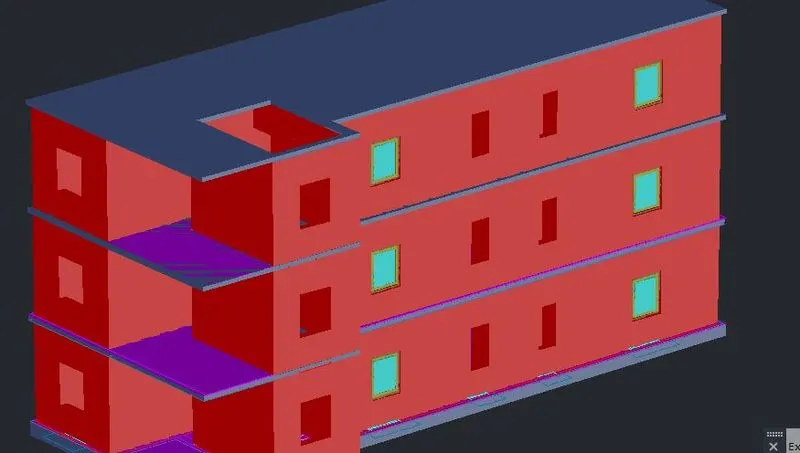
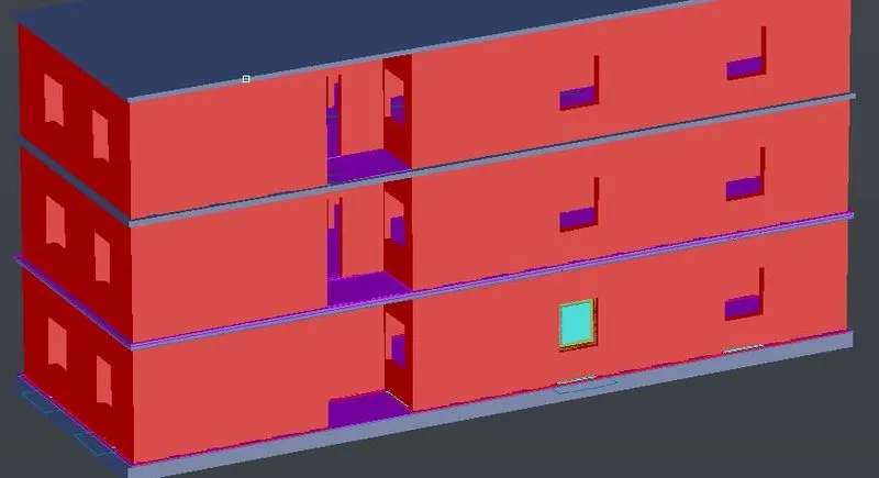
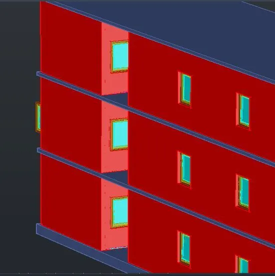
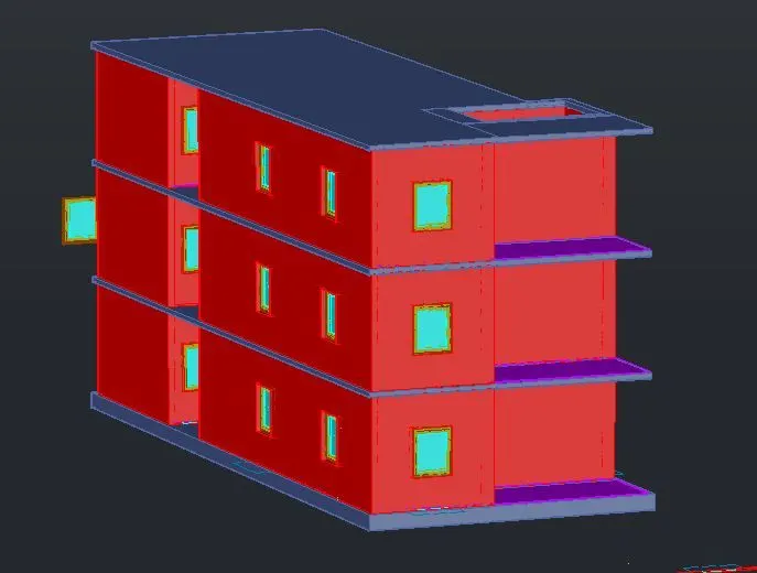
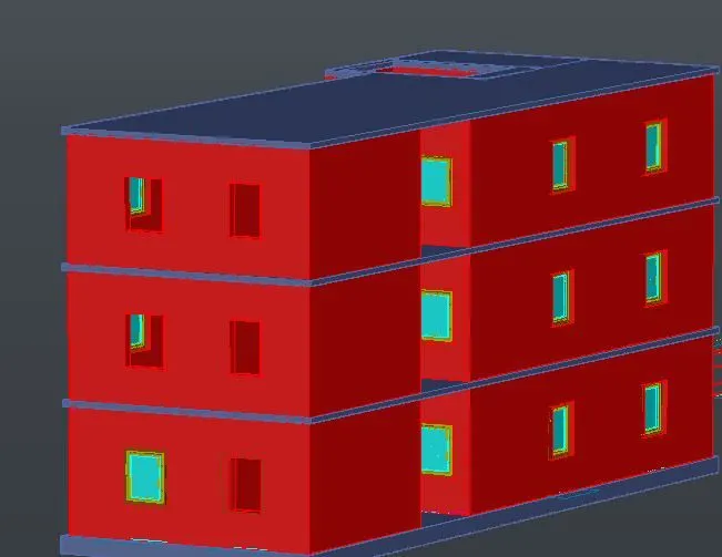
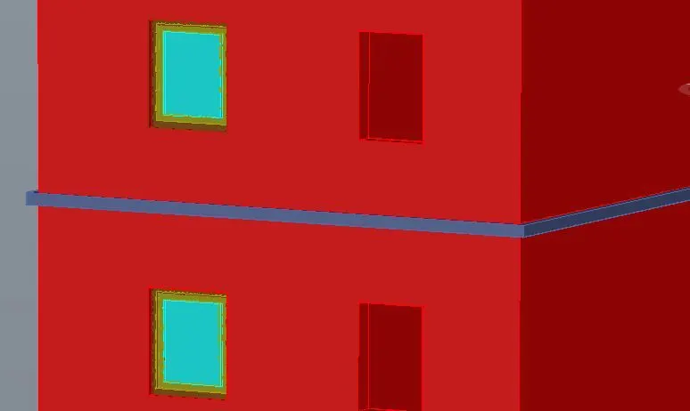
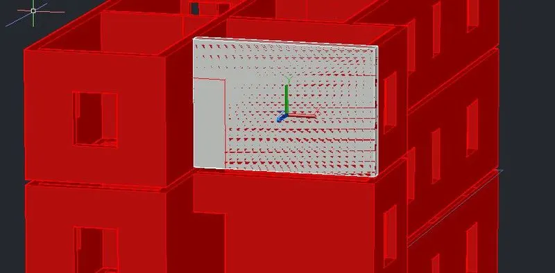
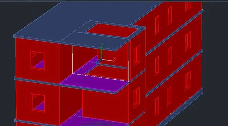
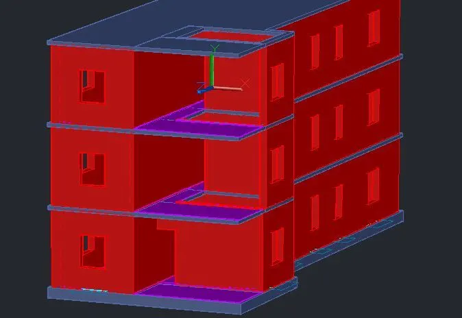
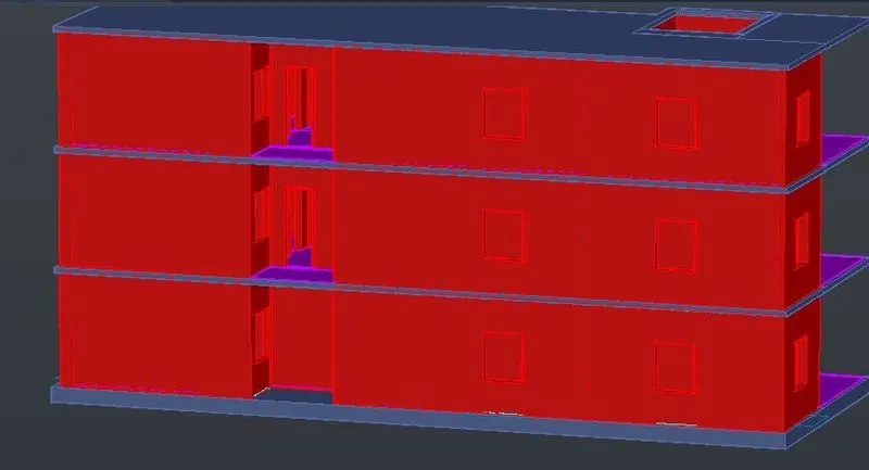
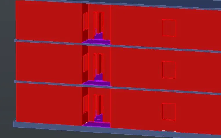
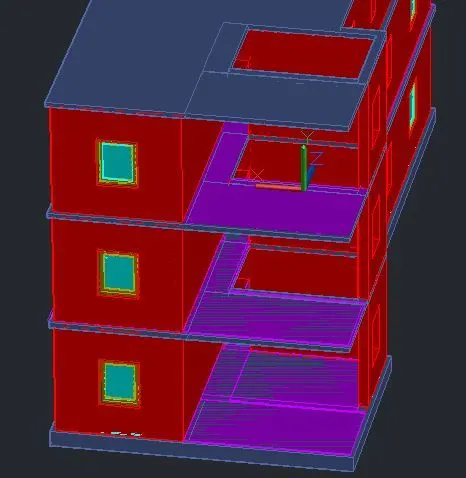
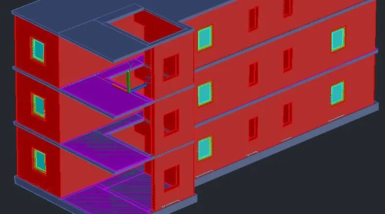
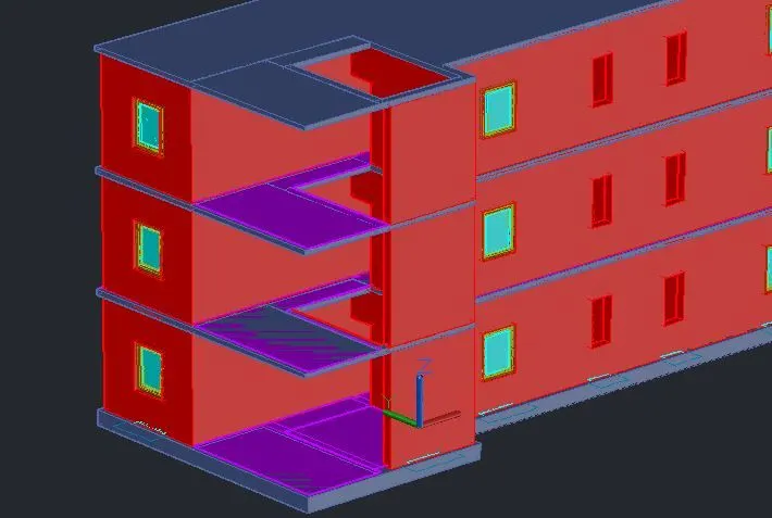
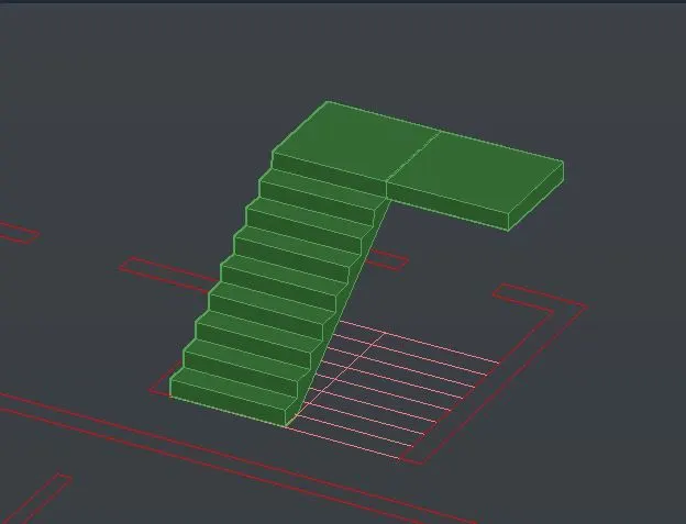
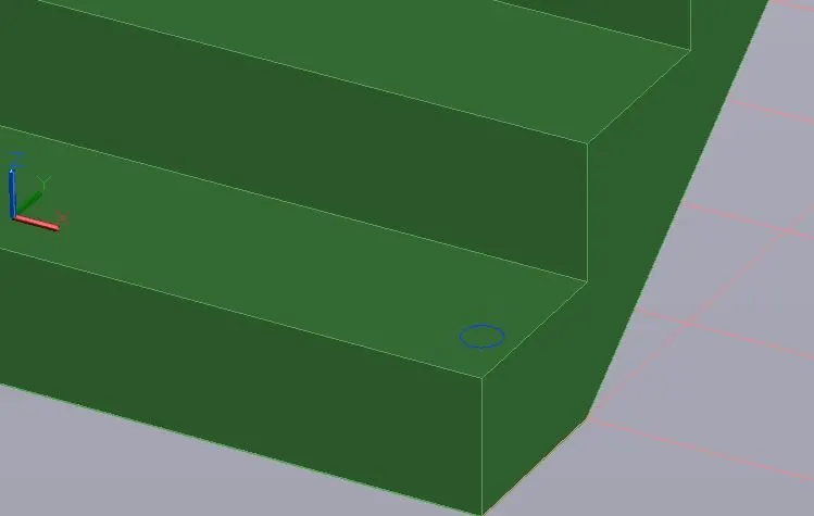
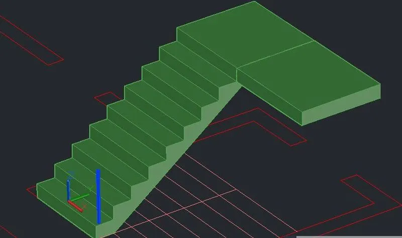
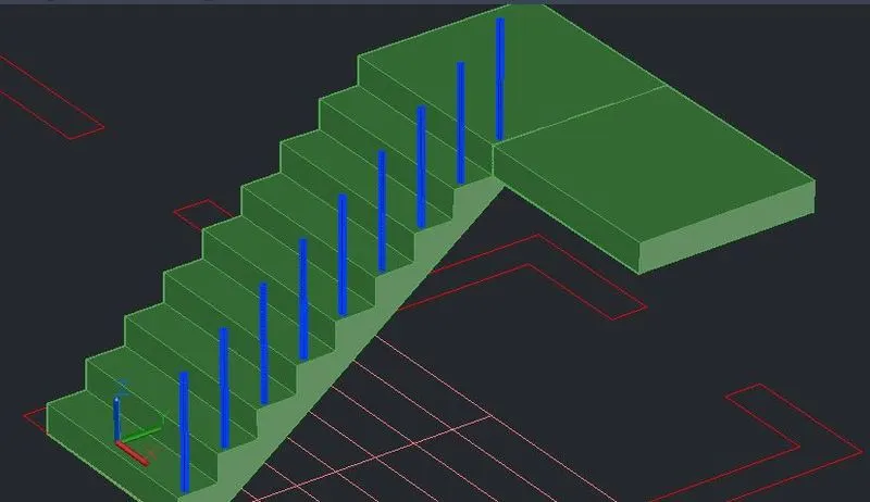
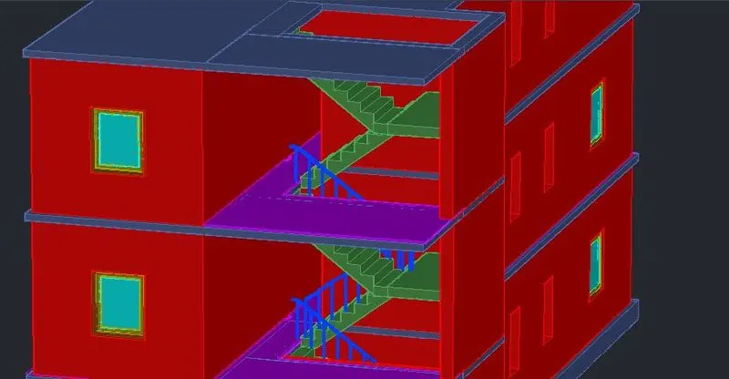
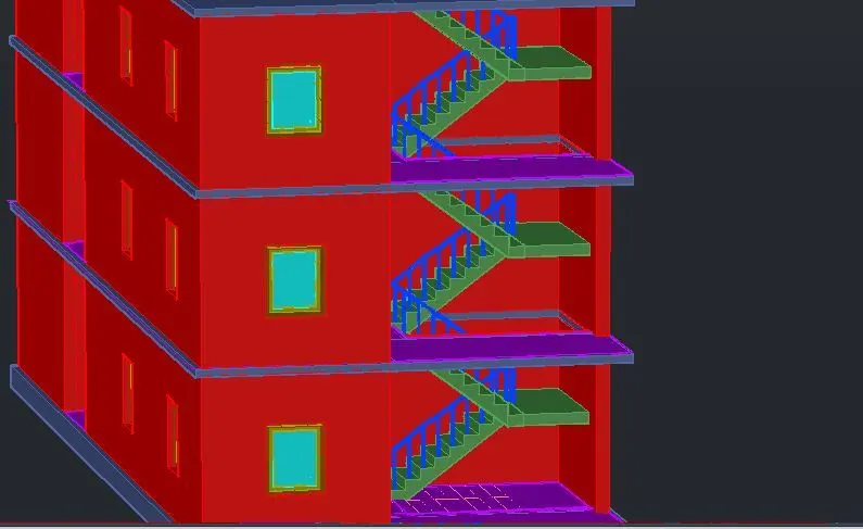
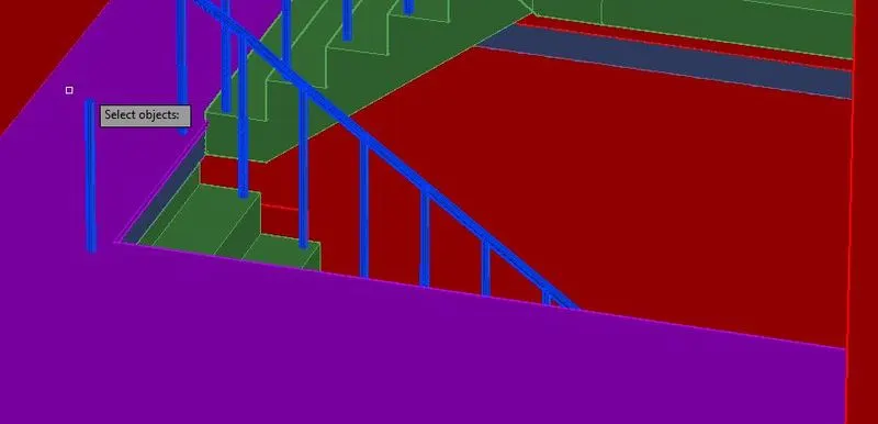
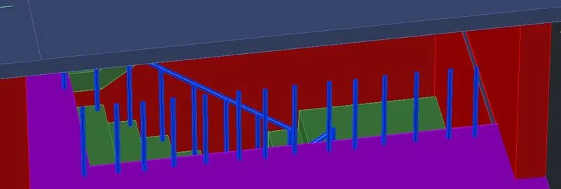
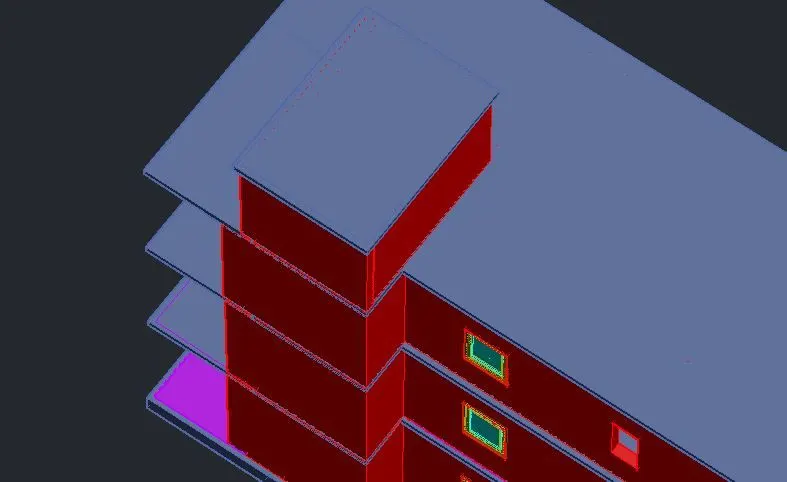
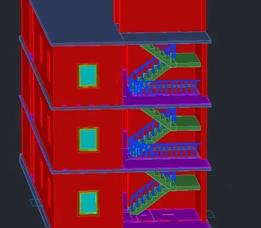
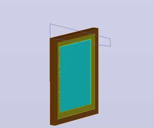
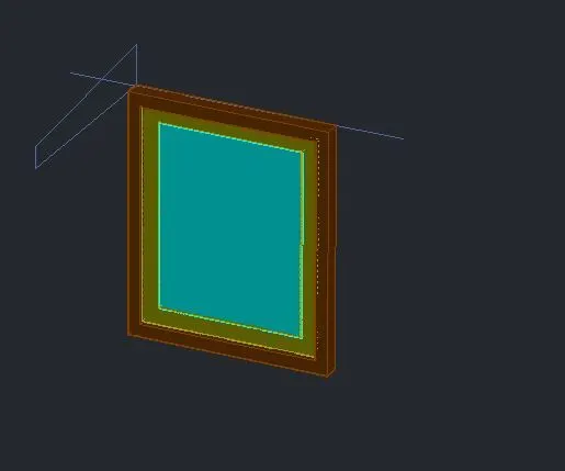
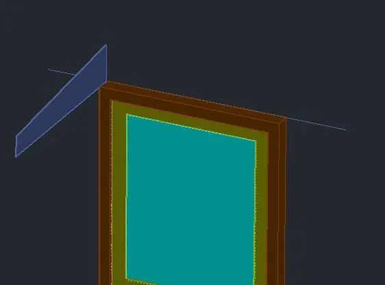
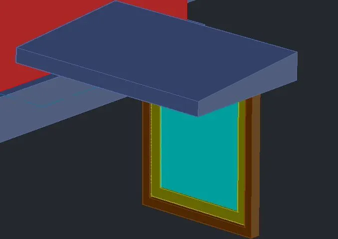
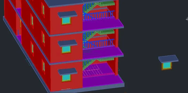
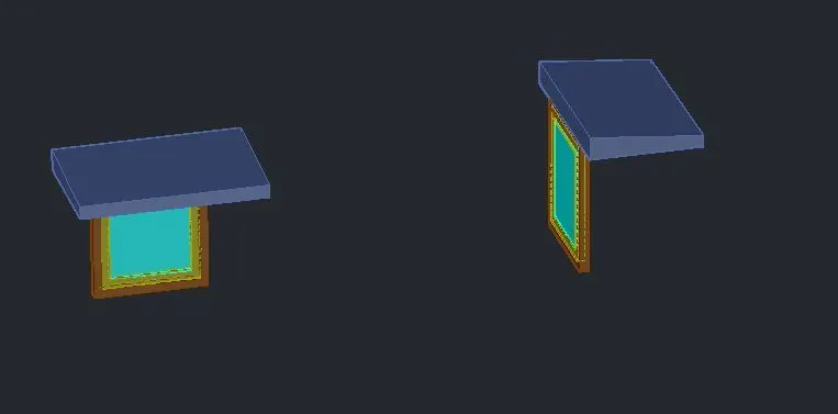
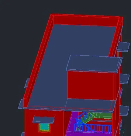
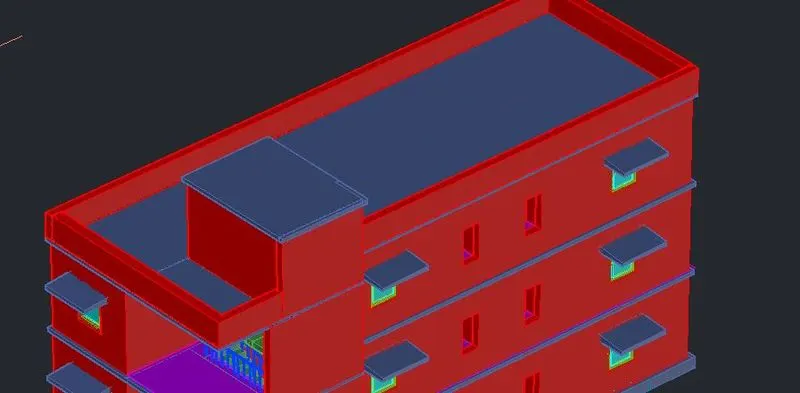
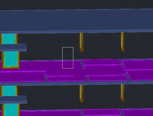

1.3.5 Procedure in rendering of the 3 dimensional residential building
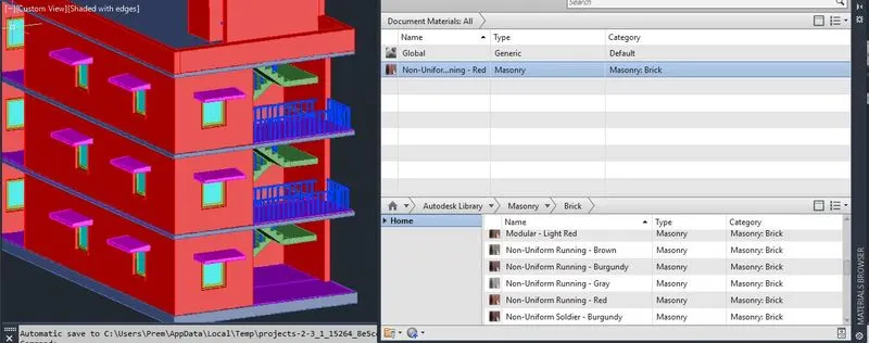
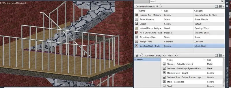
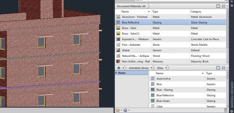
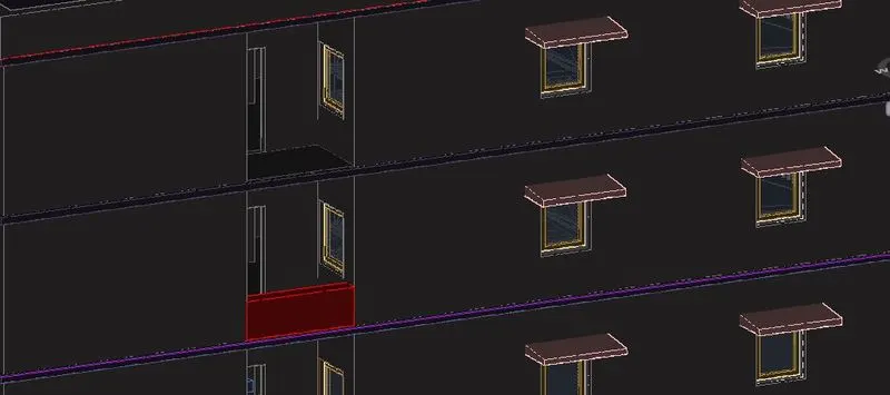
- After completion of the 3D modelling of the residential building, in the process of the rendering first the material properties have been selected as per the requirement from the material browsing.
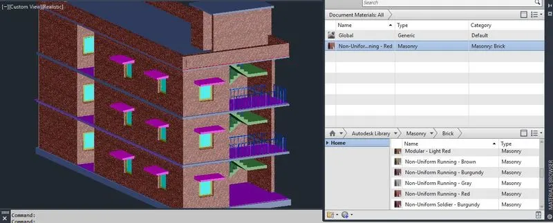
- From the material browsing, for the concrete floor, exposed aggregate medium has been selected, and brickwork is non-uniform running- red.
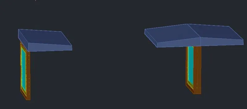
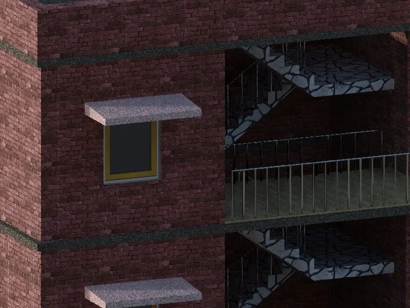
- Similarly, material for the 3D objects has been selected like for floor finishing, it is natural maple antique which is wood type, for stair, it is riverstone blue which is stone type, for railing, stainless steel- bright, for glass it is blue reflective and for sunshade work, the concrete is used rough pink.
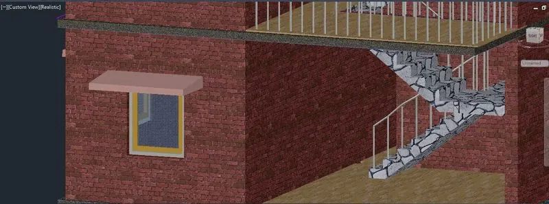
- After selecting the required materials, the next step is to assign the material to the appropriate objects. To assign the material, first the objects is selected, for selected objects, the material has been assigned according to their requirement.
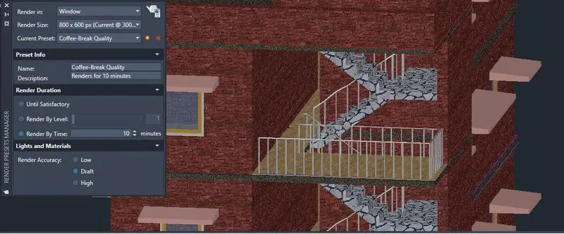
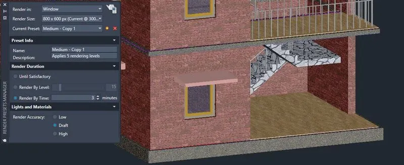
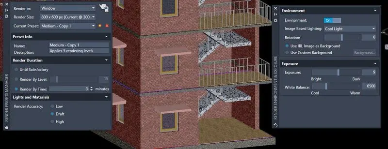
- After assigning the correct material, the next step is the rendering, in which we can change the rendering duration and accuracy based on light and material like low, drift and high which describe the material and visual in depth.
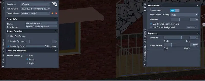
- By using the Rendering environment and exposure, we can change image based lighting, exposure and white balance.
- Here in this project, rendering duration of 3 minutes, lighting and material accuracy with drift type and rendering size of 800*600 px.
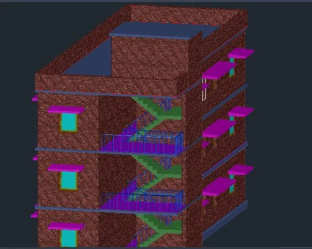
- After selecting the details of rendering, then by using RR command the rendering of the whole residential building is rendered.
- Then the rendered image of the residential building can be saved in JPEG format.
1.3.6 Step wise screenshots in rendering the modelled the 3 dimensional-residential building
1.4 Results:-
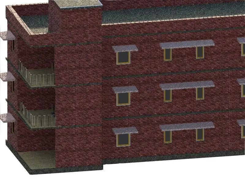
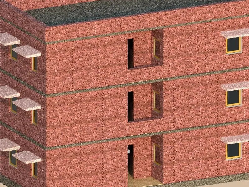
All the diagrams in AUTOCAD file that is dwg file of the floor plan of the residential building and the 3d meodelling of the residential building with rendering is given below and dwg file named "projects-2-3.dwg" has been uploaded.