Analysis & Design of RCC shear walls in the model using ETABS
1.1 Aim of the project- To know the design of RC shear wall using ETABS analysis, the basics of shear wall reinforcement detailing with respect to primary standards using AUTOCAD and to ensure the ductility reinforcement required by IS 13920-2016 satisfied in ETABS design.
1.2 Introduction
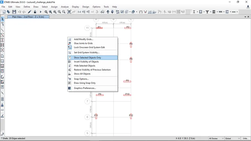
Plan of G+6 building is given below,
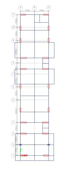
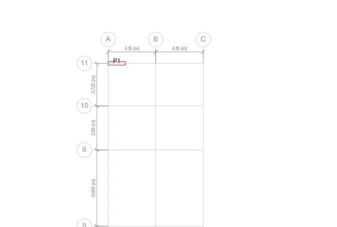
Placement of Shear plan in the building plan has been given below,
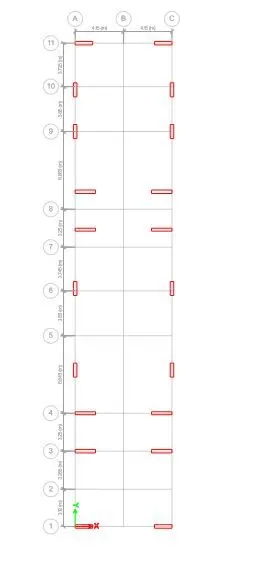
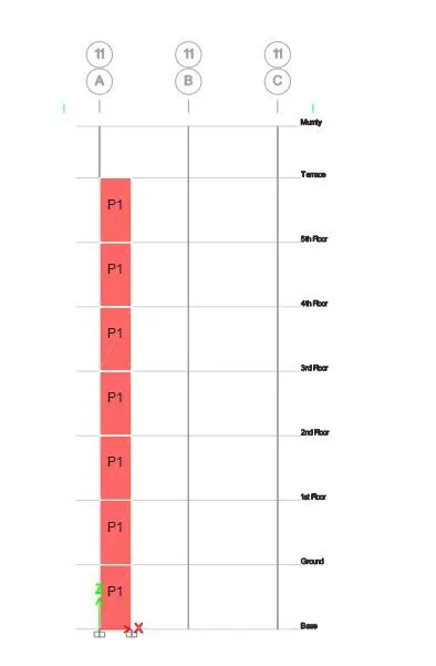
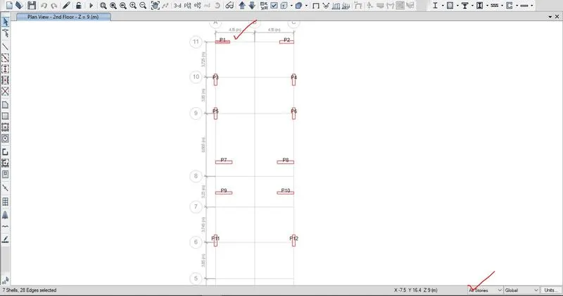
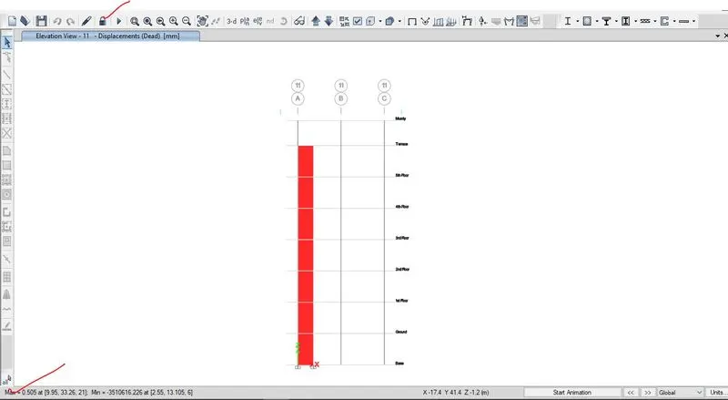
Shear wall of size 300×1500 at grid A-11 has been given below,
2.1 Procedure-
Step-1 – Firstly the ETABS file has been opened and every material properties and load properties has been checked and specially assigned pier in shear wall.
Step-2- After verification of material properties and load properties, the model has been analysed by F5 bottom or by directly clicking on run analysis bottom on ETABS.
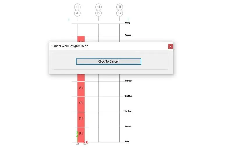
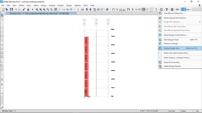
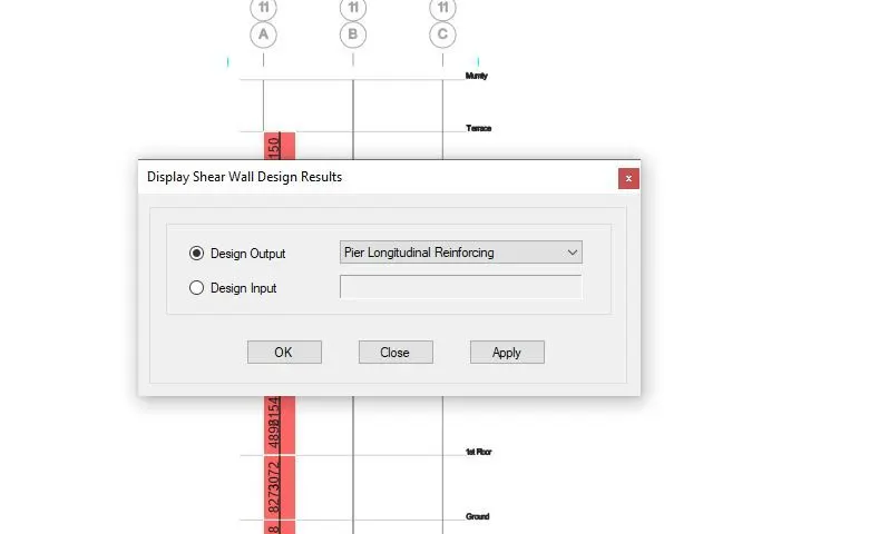
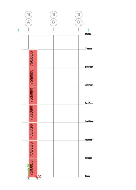
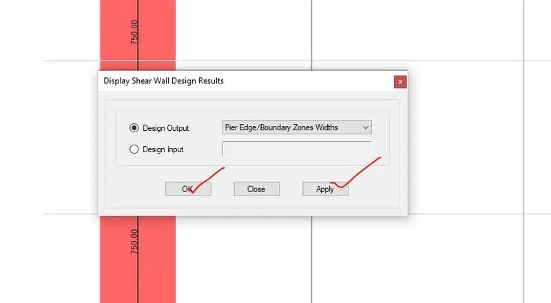
Step-3- After completion of analysis, the analysed model has been design by clicking on the shear wall design bottom as in this project, only RC shear wall has been designed which designs the pier longitudinal reinforcement, pier shear reinforcement and pier edge and boundary element width for all the load combination of RC shear wall in the model which can be checked by clicking on drop down bottom of shear wall design and the by clicking on display design info.
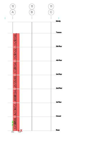
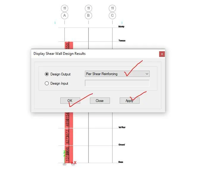
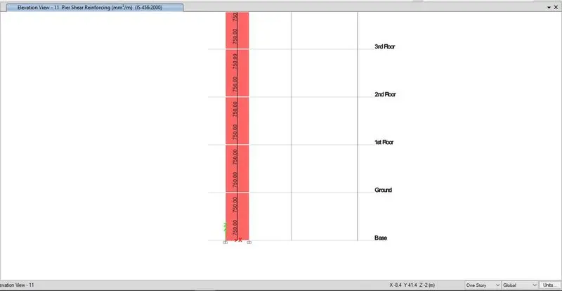
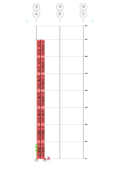
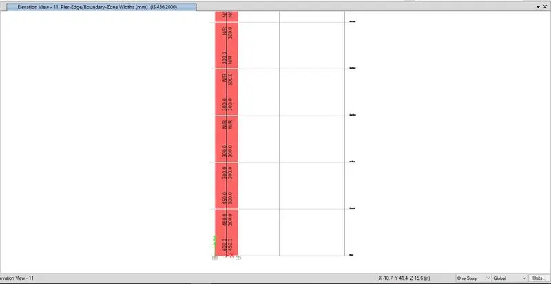
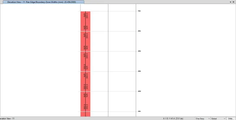
Step-4- Structural Design details i.e. pier longitudinal reinforcement, pier shear reinforcement and pier edge and boundary element width for all the load combination of shear wall in the model can be checked by right clicking on the required members and directly the designs can be access.
Step-5 After finding the design details, then the given grids i.e. has been done the detailing by using AUTOCAD.
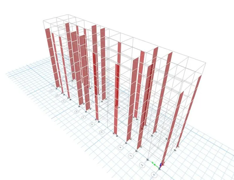
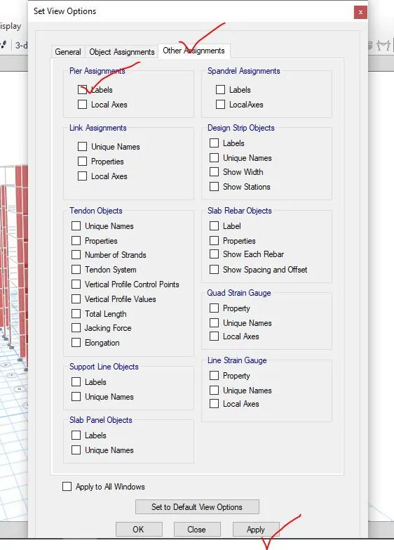
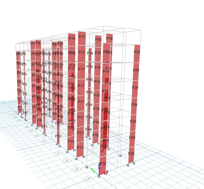
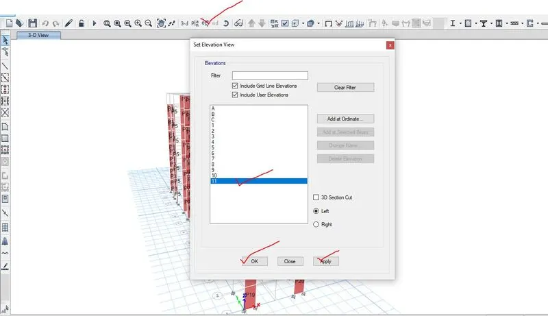
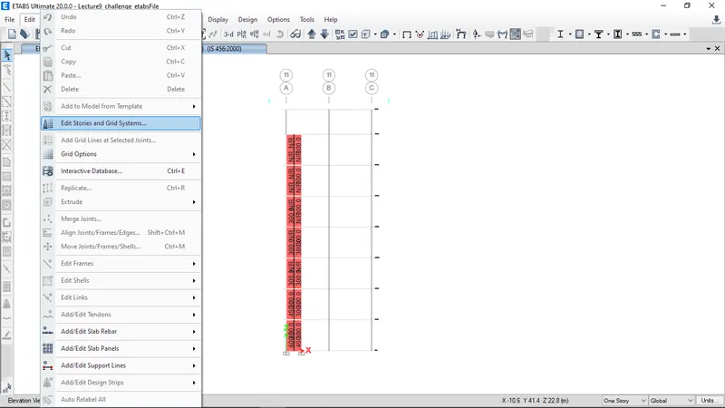
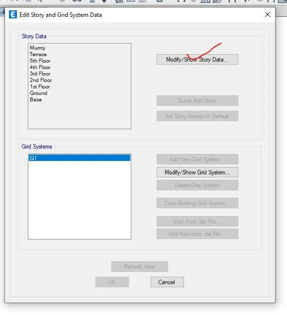
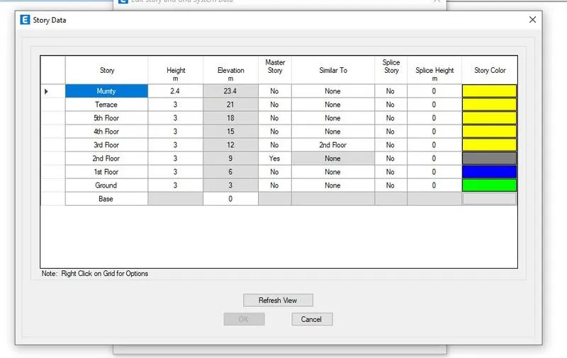
2.2 All the step wise screen shots in analysing and designing the RC shear wall at grid A-11 is given below,



3. Results and Discussion
3.1 Detailing guideline of shear wall
- Detailing rule of reinforcement concrete members
- Minimum reinforcement for shrinkage and temperature
- Ultimate limit state design rebar reinforcement
- Ductility rebar reinforcement
- Classification of the shear wall as per the IS 13920-2016 clause 10.1.4,
(HW /LW)= (21000/1500)= 14 >2
Hence, this RC shear wall is slender type of shear wall.
- Minimum net vertical reinforcement of the slender type shear wall as per the IS 13920-2016 clause 10.1.6,
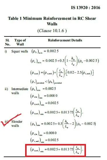
Minimum net vertical reinforcement= (0.0025+ 0.01375× (300/1500)) × (300×1500)
=0.00525 × (300×1500)
= 2362.5 which is nearly equal to 2363 mm2
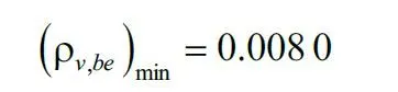
Minimum vertical reinforcement within boundary element of IS 13920-2016, Table-1 (iii)
- For 600mm width of boundary element,
Minimum vertical reinforcement= 0.0080 × (300×600) = 1440 mm2
- For 450mm width of boundary element,
Minimum vertical reinforcement= 0.0080 × (300×450) = 1080 mm2
- Minimum horizontal reinforcement of shear wall as per IS 13920-2016 Table-1 (iii)

(ph)= 750/ (300×1000) =0.0025, hw= 21000mm, Lw=1500mm,
(ph)min= 0.0025+ 0.5×(( 21000/1500)-2)×( (0.0025-0.0025))= 0.0025
(ph)min= 0.0025
Minimum horizontal reinforcement of shear wall= 0.0025 {which is same as 750mm2/m}
- Maximum diameter of rebar for shear wall as per IS 13920-2016 clause 10.1.8
1/10th of wall thickness = (300/10) = 30mm {Commercial rebar shall be adopted}
- Confinement reinforcement spacing for boundary element as per IS-13920-2016 clause 10.4.4
- (1/3)rd of minimum member dimension =(300/3)= 100mm
- 6 times smallest main bar= 6×25= 150mm
- 150mm permissible if vertical bars are spaced a maximum 200mm
Maximum spacing of confinement reinforcement in boundary element 150mm but 125mm of spacing is provided.
- Confinement reinforcement within boundary element as per IS 13920-2016 clause 10.4.4
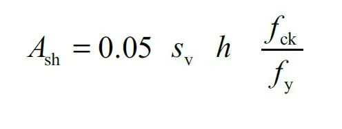
sv= 125mm, h=1000mm, fck=25 N/mm2 , fy=415 N/mm2 , Ash= 377 mm2
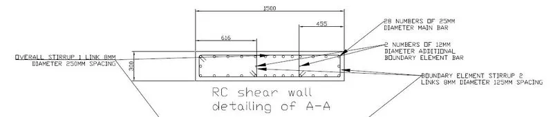
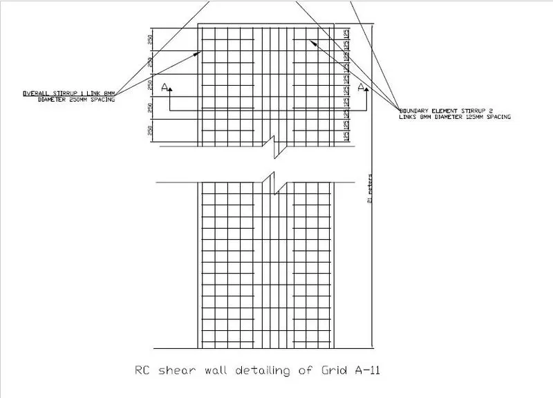
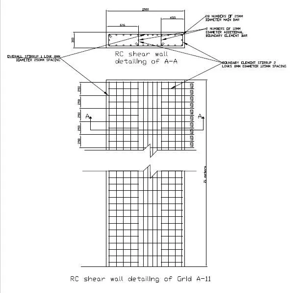
- After getting the value of vertical reinforcement, horizontal reinforcement, vertical reinforcement in boundary element and confinement reinforcement in within boundary element of RC shear wall at grid intersection A and 11 by using ETABS and IS 13920-2016, the detail reinforcement has been drafted using AUTOCAD which is given below,
3.2 NOTE-
The results in analysing and designing of the RC shear wall at grid A-11 as per the given data by using ETABS i.e. the .edb file named as “Lecture9_challenge_etabsFile” and detailing of reinforcement for grid A-11 which has been drafted in AUDOCAD i.e. dwg file named as “Shear wall reinforcement” and pdf file for reinforcement detailing named as “SHEAR WALL reinforcement.pdf” have been uploaded below.