Creating a Floor plan, Footing detail and Isometric view using AutoCad
1. Aim and introduction
1.1 Aim of the challenge: - To Creating a Floor plan, footing detail and Isometric view using AutoCAD.
1.2Introduction: - In the first diagram (C1) i.e. the cross-section of the load bearing wall over spread footing. This can be drawn by using tool line and by doing offset with ortho mode, but in the 2nd diagram (C2) i.e. cross-section of the isolated footing which can also be drawn by using line tool with ortho-off. To draw the symmetric diagram, mirror tool can be used to draw the diagram easily.
In the 3rd diagram (C3) shows the line diagram of the two bedrooms building having bedroom size of 3.6 *3.6 and living room of 3.6 *4.2 which also can be drawn by using the line tool.
In the 4th diagram (C4) I.e. cross-section of the load bearing wall showing foundation details which can be drawn by using the line tool and offset operation.
Isometric view of the steps, isometric view is the kind of three dimensional which shows the diagram with 30 degrees prospective.
Isometric snap can be on from snap and grid in the drafting setting. There are three type of isoplane i.e
- Isoplane left
- Isoplane right
- Isoplane top
To change the one isoplane to other by using F5 command.
1.2.1 Command used in the all the diagrams
- ‘UN’ for units
- ‘LIMITS’ for specify the limit of the sheet.
- ‘L’ (for line)
- ‘O’ for offset
- ‘DS’ for drafting setting
- ‘F5’ to change the isoplanes (left, right and top)
- ‘DIM ‘for dimension
- ‘DDIM’ for dimension style manager
- MT for multi text
1.3 Procedure
1.3.1 Procedure for drafting the diagram C1, C2, C3, C4
Step 1- After opening the software, unit should be checked by using the UN command.
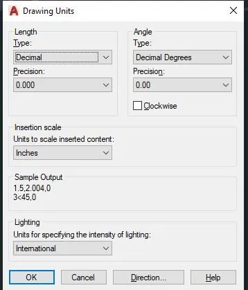
Step 2- limit should be specified the from <0.000,0.000> to <12.000,9.000> by using LIMITS command.
Step 3- Then by using line command with the direct distance entry coordinate system, the given diagram has been drawn.
Screen shots of diagrams C1,C2, C3 and C4 has been given below,
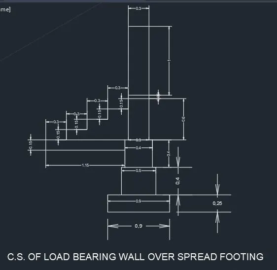
(C1-cross-section of the load bearing wall over spread footing)
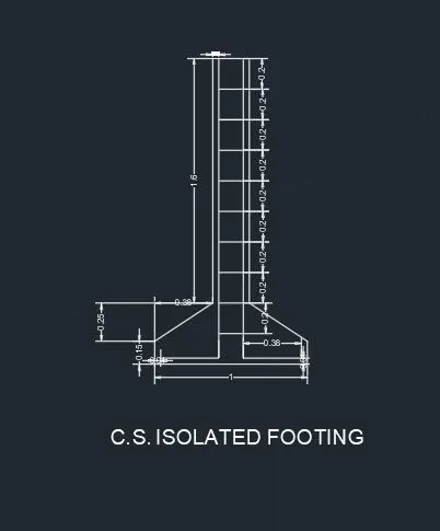
(C2- Cross-section of isolated footing)
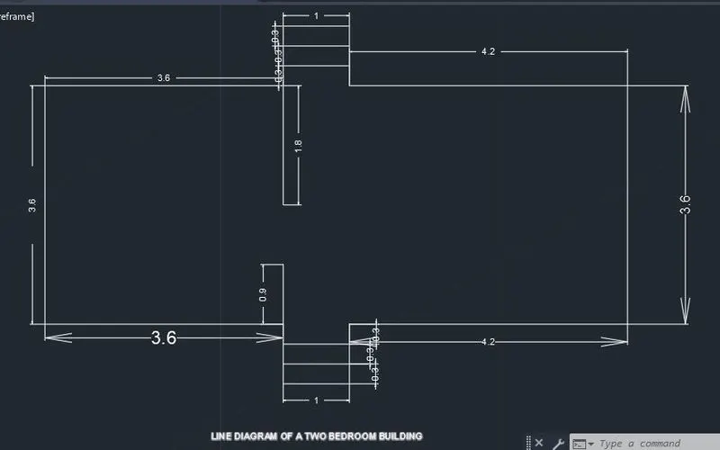
(C3- line diagram of a two bedroom building)
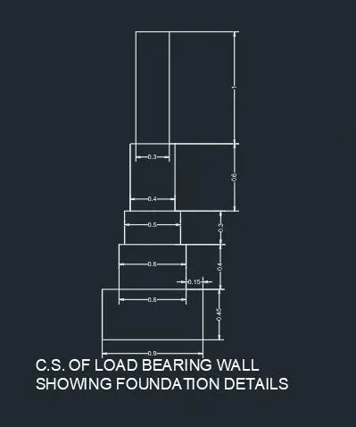
(C4- cross-section of load bearing wall showing foundation details.)
1.3.2 Procedure for drafting the diagram C5 and C6
Step 1- After opening the software, unit should be checked by using the UN command.
Step 2- limit should be specified the from <0.000,0.000> to <12.000,9.000> by using LIMITS command.
Step 3- Then isometric snap should be on for the isometric objects C5 and C6, by using F5 command the isoplanes can be changed. With the help of f5 command, the diagram C5, C6 can be drawn according to their planes.
Step 4- Then by using line command with the direct distance entry coordinate system, the given diagram has been drawn.
Screen shots of diagrams C5 and C6 has been given below,
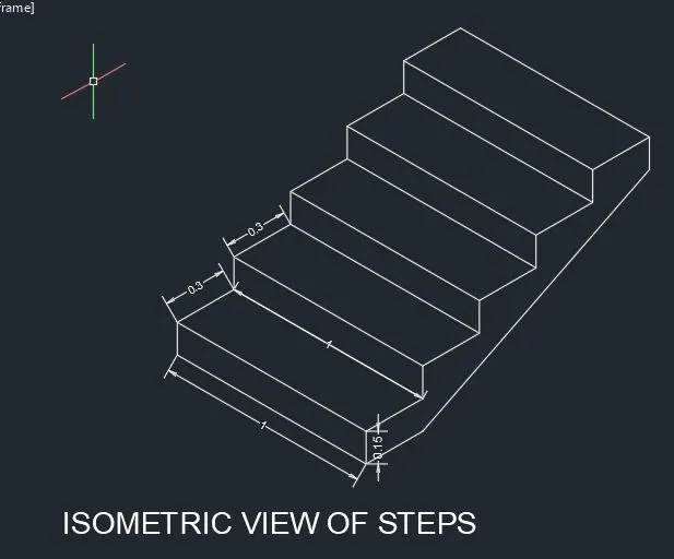
(C5- Isometric view of steps)
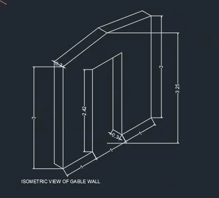
(C6- Isometric view of gable wall)