Project 1
1.1Aim of the Project- To Design a multi-storey Residential Building located in Bangalore using STAAD Pro Connect Edition in which beam and columns are designed using STAAD RCDC, foundation of the building using STAAD FOUNDATION and slab has been designed usinf excel. To prepare the BBS of the beams and column and foundation using STAAD RCDC and STAAD FOUNDATION and to draft the plan, beam layout, column layout by using AUTOCAD.
The specification must be as follows:
|
Building floors |
G + 6 + R |
|
Plan dimension |
B = 25m , L = 16m |
|
Storey Height |
h = 3.5m |
|
Soil |
Hard soil |
|
Use |
Residential Purpose |
|
Safe Bearing Capacity |
180 kN/m2 |
|
Maximum slab thickness |
150mm |
2.1 Introduction-
Building specification to model, analysis and design of the building is given below,
Building floors G + 6 + R
Plan dimension B = 25m, L = 16m
Storey Height h = 3.5m
Soil Hard soil Use
Safe Bearing Capacity 180 kN/m2
Maximum slab thickness 150mm
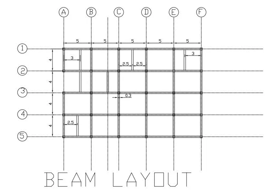
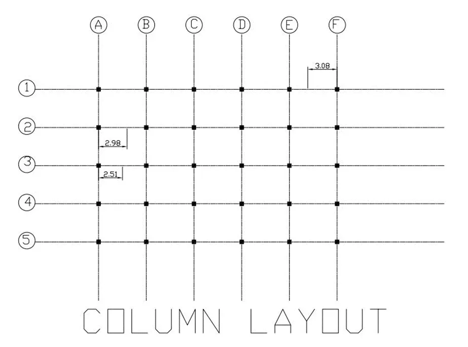
2.2 Plan, beam layout and column layout diagram of the building has been given below,
2.3 Description of structure
|
All the structural element like beams, columns, slab are the concrete structure including foundation. |
Beam-RCC Column-RCC Slab- RCC Foundations – RCC Plinth Beams – RCC |
|
Number of beam |
48 no of primary beam and 5 no of secondary beams in all the storey |
|
Number of column |
30 no of columns |
|
Number of slab |
20 no slabs in each storey |
|
Number of foundation |
30 of isolated foundation |
|
Description of the foundation for the building |
Isolated/Combined foundation |
2.4 DESIGN LOADS
Dead load shall mean the total weight of structures and/or foundations, and all materials permanently attached there to or supported thereby. The unit weight of material conform to IS 875 – Part - I.
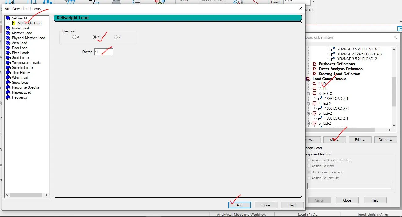
Self-weight- self weight of the building can be calculated directly by Staad pro.
Unit weight of R.C.C Members = 25.0 kN/m3
Unit weight of Structural Steel = 78.5 kN/m3
Unit weight of brick wall= 18 kN/m3
2.4.1 Loads on the floor slab
· Interior partition= 1 KN/m2
· Floor finishing load= load of slab+ load of tile finishing
= 25×0.150+ 17×0.05
=4.6 KN/m2
· Miscellaneous= 0.50 KN/m2
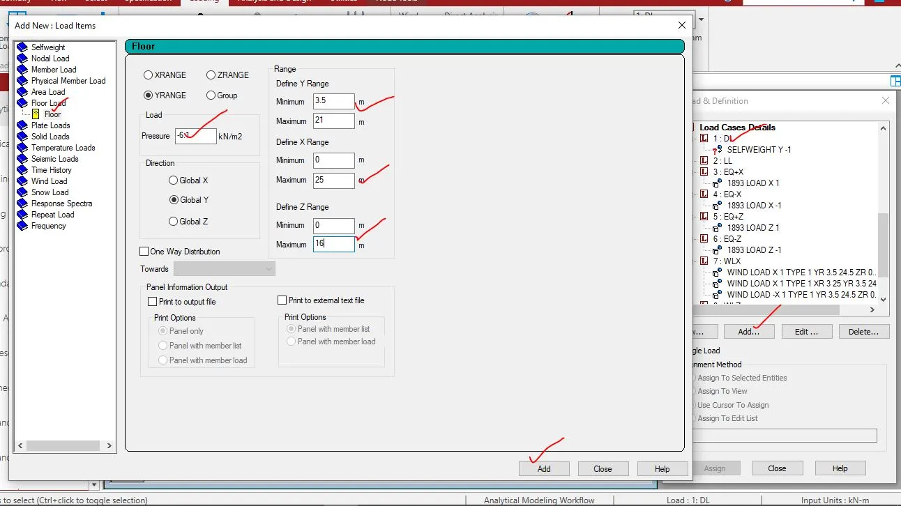
· Total loads on the floor slabs= 6.1 KN/m2
2.4.2 Loads on the roof slab
· Insulation and water proofing= 0.20 KN/m2
· MEP services loads below roof slab= 0.50 KN/m2
· Miscellaneous= 0.50 KN/m2
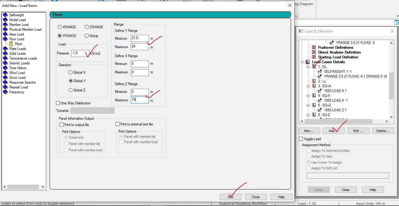
· Total load on roof slab= 1.5 KN/m2
2.4.3 Loads on the beams
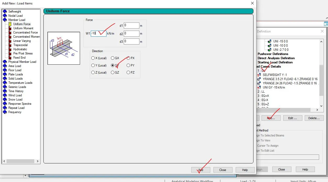
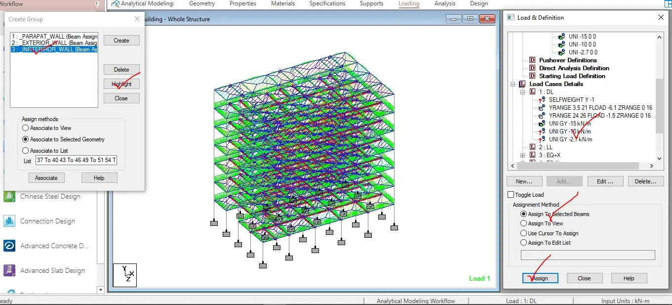
· Brick wall load (exterior wall)= 18× 0.23×3.5 =14.49 KN/m
· Brick wall load (interior wall)= 18× 0.15×3.5 =9.45 KN/m
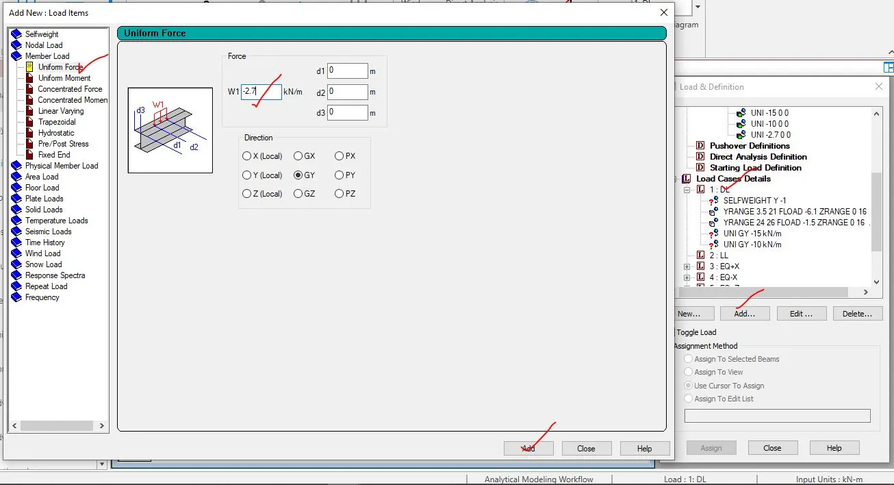
· Parapet wall load on the roof= 18× 0.15×1 =2.7 KN/m
2.4.4 Live Loads
Live loads shall mean the moving or movable external loads on structures, foundations and buildings produced by people, tools and furnishings of buildings etc. which are not permanently fixed there to. These are applied as per IS 875 (Part II). Live load to be considered for all the structures is as follows.
· Kitchen- 2 KN/m2
· Bed rooms-2 KN/m2
· Toilets/ wash room-2 KN/m2
· Living room-2 KN/m2
· Store room-3 KN/m2
· Balconies-3 KN/m2
· Dining room-2 KN/m2
· Corridor/ passage/ stair case including fire escape-3 KN/m2
2.4.5 Earthquake loads
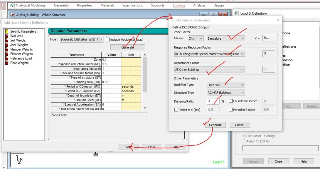
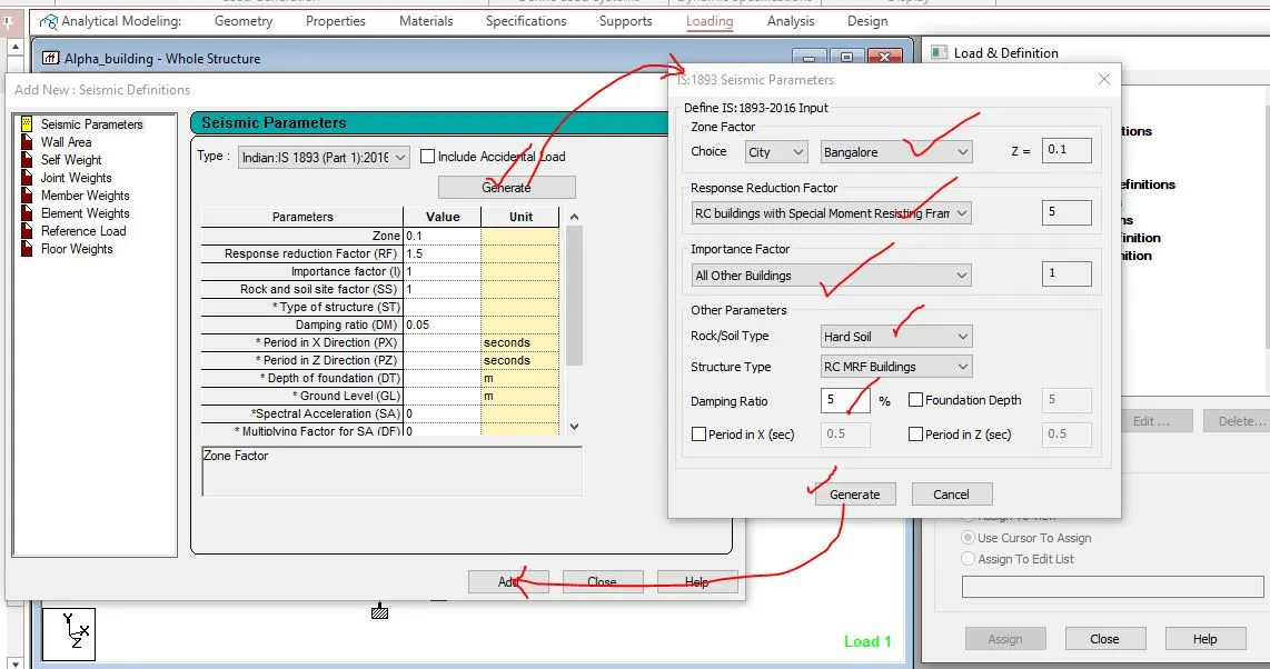
As per IS 1893-2016 the structure is considered to be located in Zone II (0.24 g Acceleration) that is in Bangalore of the seismic map of India.
The separate seismic analysis report (SAR) would be shared highlighting the findings based on the dynamic analysis carried out considering latest IS 1893:2016.
The following parameters are used for seismic design in all structures:
|
Zone factor (Z) |
=0.10 (ZONE II) |
|
Importance factor (I) |
=1 |
|
Response reduction factor (R) |
=5 |
|
Soil type |
=I |
The category of a building as per the IS 1893-2016 comes under SMRF i.e. Special
R.C moment resisting frame.
The horizontal earthquake forces have been calculated for the full dead load and 50% of live load as applicable as per IS: 1893-2016.
2.4.6 Wind loads
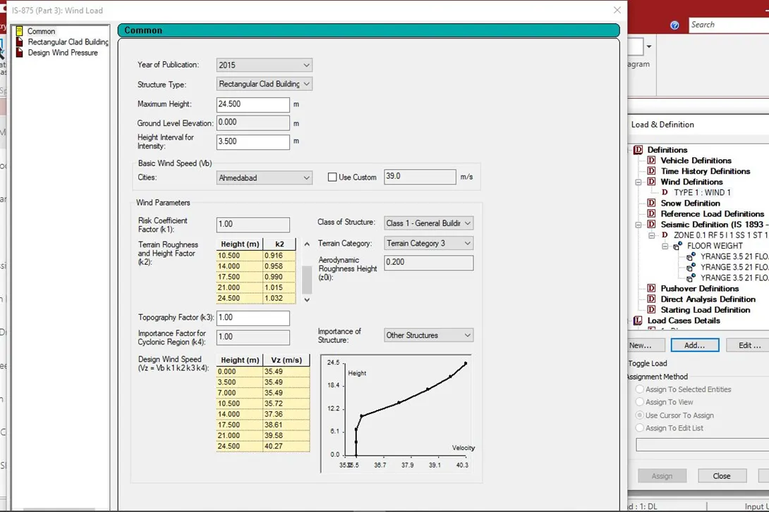
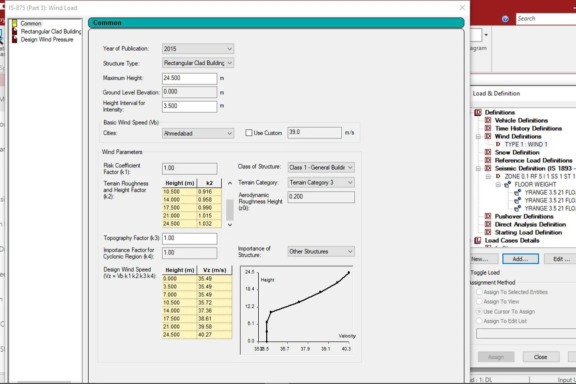
The wind loading will be as per IS 875(Part–3):2015 and the Basic wind pressure (Pz) shall be determined based on the following formulae:
Pz=0.6*(Vz)2 N/m2
Where,
Vz - Design wind speed at height z in m/s
Vz = (Vb x k1 x k2 x k3 x k4) N/m2
Where,Vb- Basic wind speed m/sec = 33 m/s (For Bangalore)
k1 - Risk Co-efficient factor for mean probable design life of structure (i.e.50 years) as minimum 1.00
k2 -Terrain, height and structure size factor depending on the terrain category (Terrain Category 2) (to be reconfirmed with height of structure at execution stage)
k2 has been calculated as per the IS 875 part III, clause no- 6.3.2.2, table no 2 and page no-8
k3 - Topography factor i.e 1.0
k4 - Importance factor for cyclonic region i.e 1.0
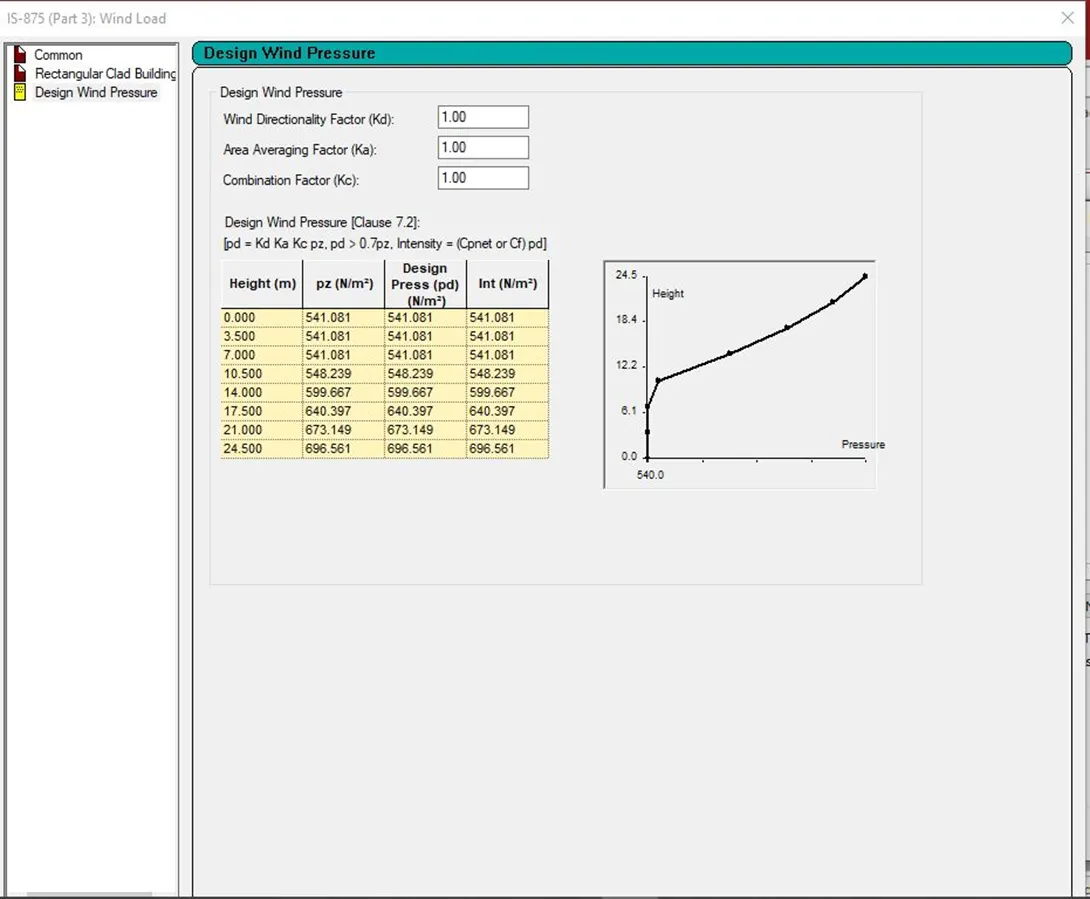
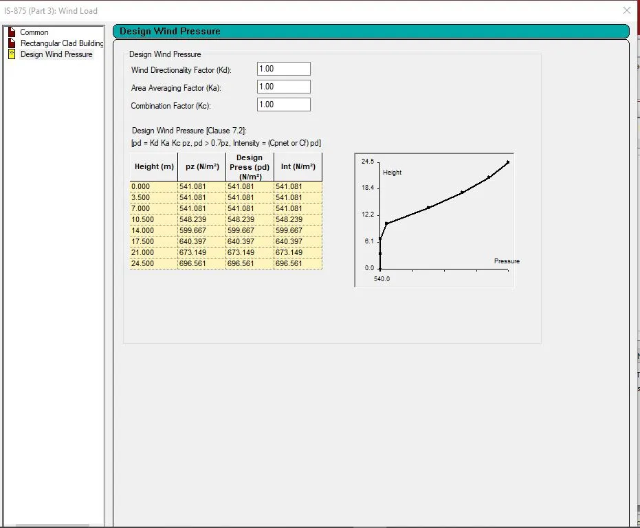
The design wind pressure shall be determined by the following formulae:
Pd= Kd * Ka* Kc * Pz
Where,
Kd - Wind directionality factor
Ka - Area averaging factor
Kc - Combination factor
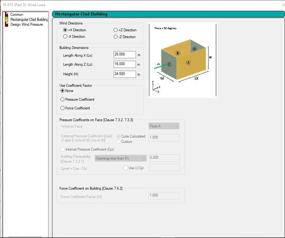
Considering the building elevation and configuration of roof, external coefficient & other parameters would be workout as per criteria given in IS 875 (part 3):2015, clause 7.3.3.2 and 7.3.3.3.
In addition to the above, following guidelines needs to be followed:
Pressure coefficient for the local effects should be used for calculation of forces on local areas affecting roof sheeting, glass panels and individual claddings including their fixtures as per clause 7.3 of IS 875 (Part3).
2.4.7 REFERENCE CODES & STANDARDS
|
IS: 456 – 2000 |
Code of practice for Plain & Reinforced concrete |
|
IS: 875 (Part I) |
Code of practice for design loads of dead load for Building Structure (Part I) |
|
IS: 875 (Part II) |
Code of practice for design loads of live load for Building Structure (Part II) |
|
IS: 875 (Part III) |
Code of practice for design loads of wind load for Building Structure (Part III) |
|
IS: 875 (Part IV) |
Code of practice for design loads of earthquake load for Building Structure (Part IV) |
|
IS: 1893 - 2016 |
Criteria for earthquake resistant design of Structures |
|
IS: 1786 - 2008 |
High Strength deformed bars & wires |
|
IS: 13920 -2016 |
Ductile Detailing of Reinforced Concrete Structure subjected to Seismic Forces |
|
IS: 4326 – 1993 |
Code of practice Earthquake Resistant Design and Construction of Buildings |
|
IS: 2911-1998 |
Code of Practice for Design and Construction of Pile Foundation |
|
IS: 8009 |
Code of Practice for Calculation of Settlement of Foundation |
|
IS: 6403-1981 |
Code of Practice for Determination of bearing Capacity of Shallow Foundation on Rock |
|
SP: 16 -1997 |
Design Aids For Reinforced Concrete to IS: 456 |
|
SP: 20 -1981 |
Explanatory Handbook on Masonry Code. |
|
SP: 22 -1982 |
Explanatory Handbook on Codes for Earthquake Engineering |
|
SP: 34 -1987 |
Handbook on concrete reinforcement detailing |
|
IS: 15988: 2013 |
Seismic Evaluations and Strengthening of Existing Reinforced Concrete Buildings — Guidelines |
|
NBC: 2016 |
National Building code of India. |
3.1 Design Basis Report for the project
Design basis report for the project has been prepared which has been upload below named as DBR of Residential building_alpha_bangalore_project-1.pdf.
4. Creation of structural model using STAAD Pro Connect Edition
4.1 Procedure in creating structural model using STAAD Pro Connect Edition
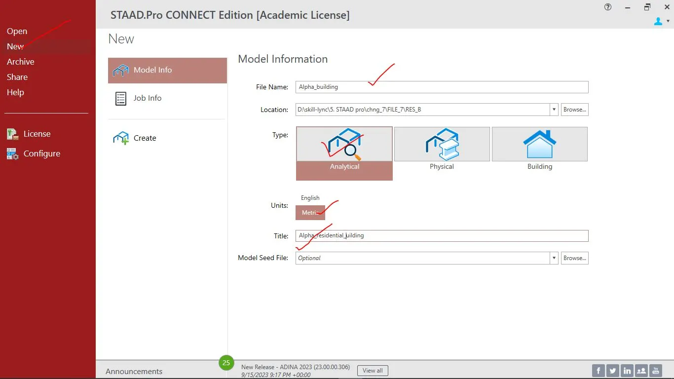
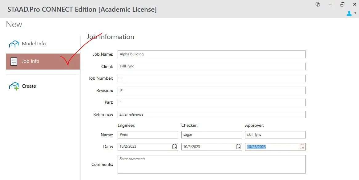
Step-1- after opening of the staad pro software the model information and project information has been given.
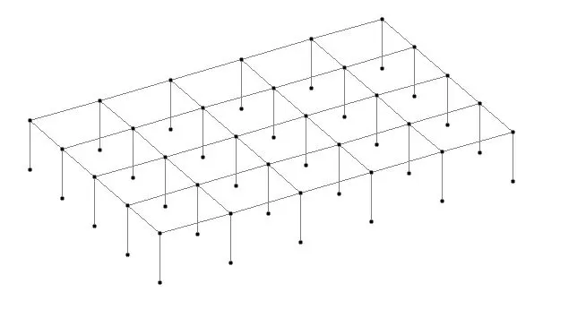
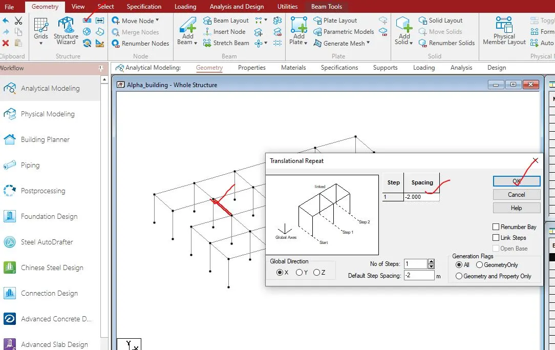
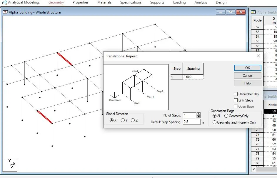
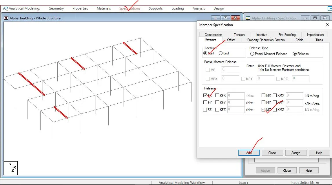
Step-2- In creation of the analytical model, the geometry of the model has been created in this step by using the node, beams and translational repeat for the all the floor as per the plan and elevation has been decided. For the secondary beams, the internal hinged has been created the end of the secondary beam.
Step-3- after the creation of the model the, the properties of the beam and column i.e. the shape, size and material has been defined and assigned to the appropriate members.
Step-4- Then the support condition i.e. fixed support has been created and assigned to the base of the structure.
4.2 All the procedural screen shots in creation of the structural model using STAAD pro.
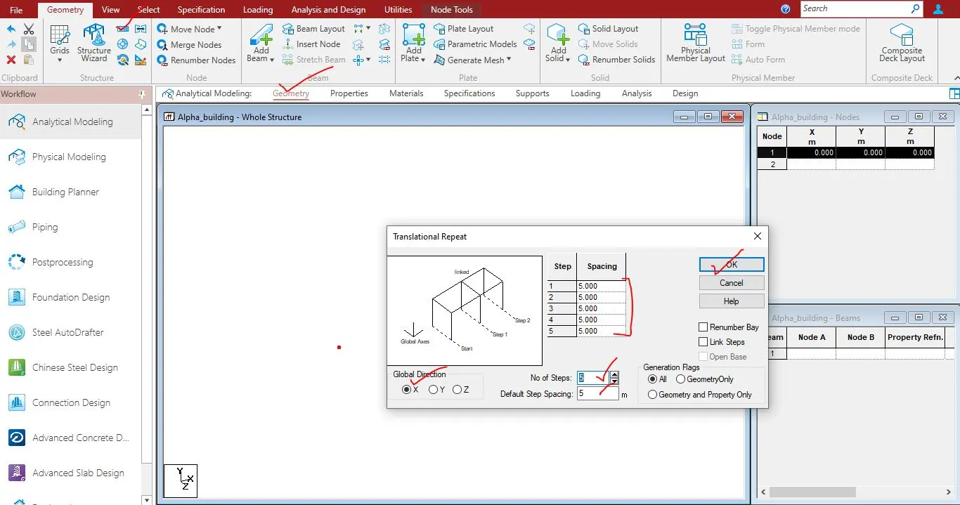
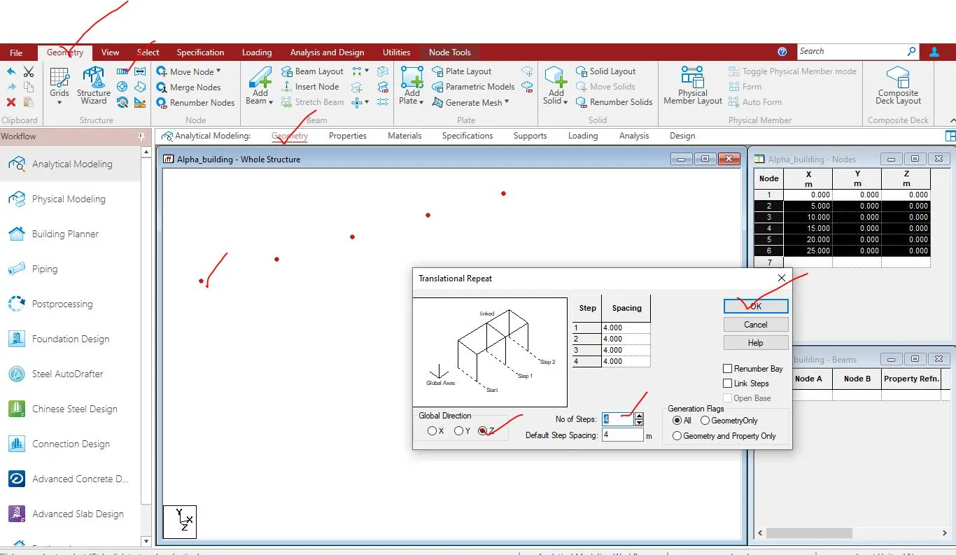
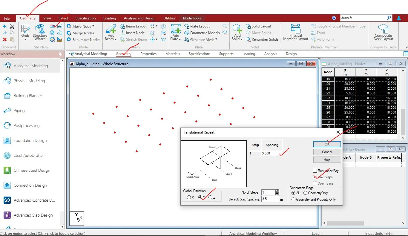
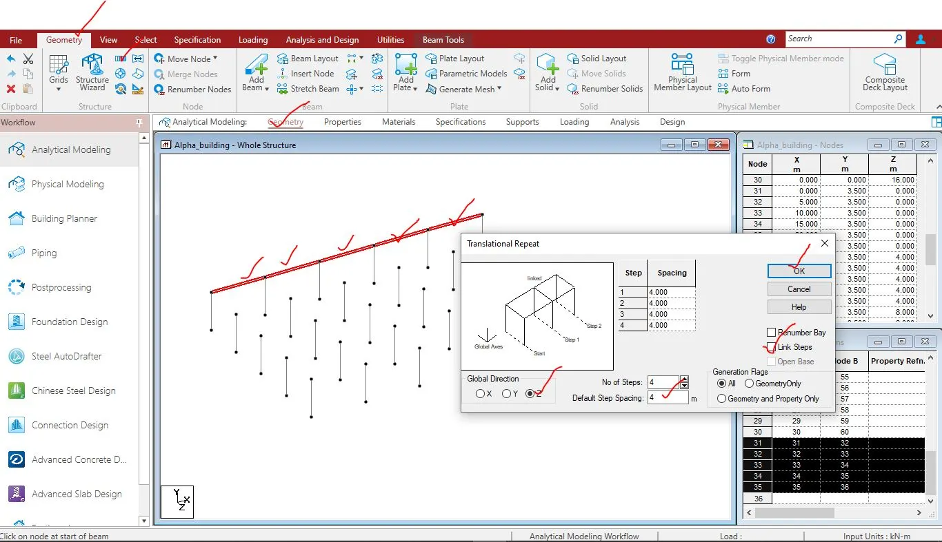
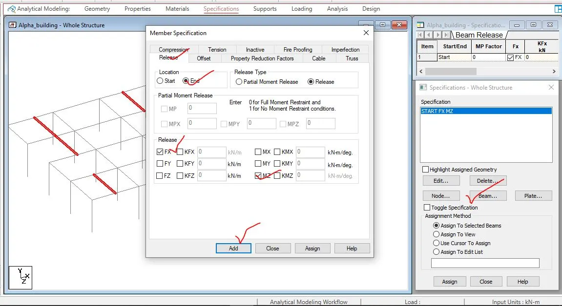
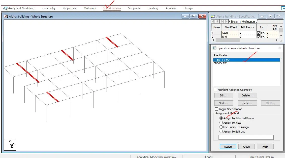
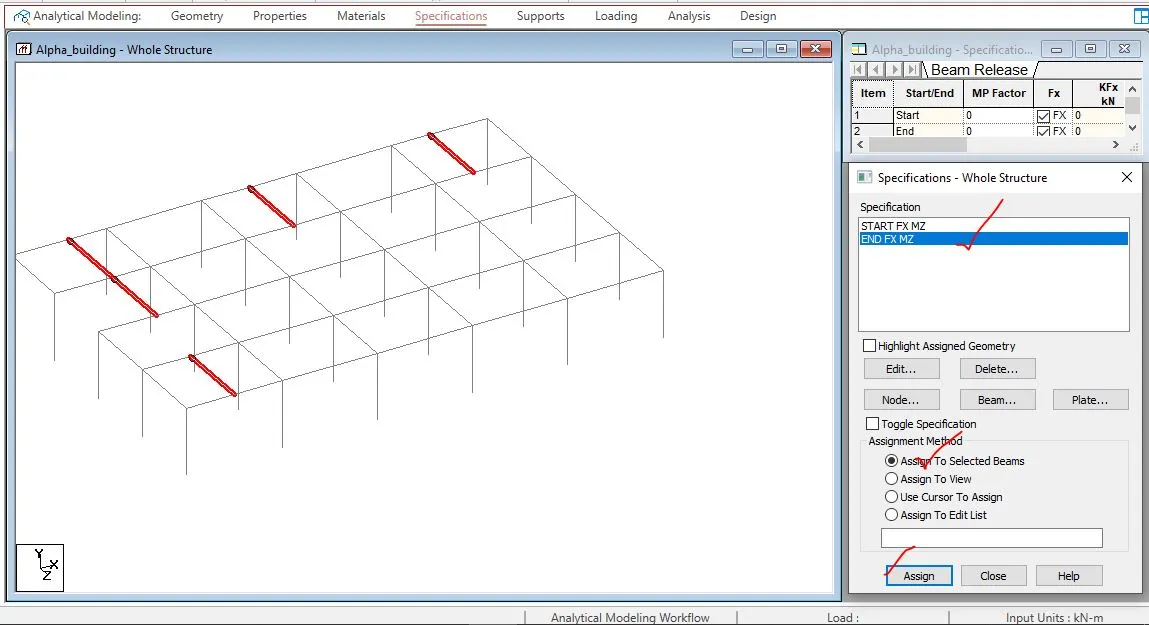
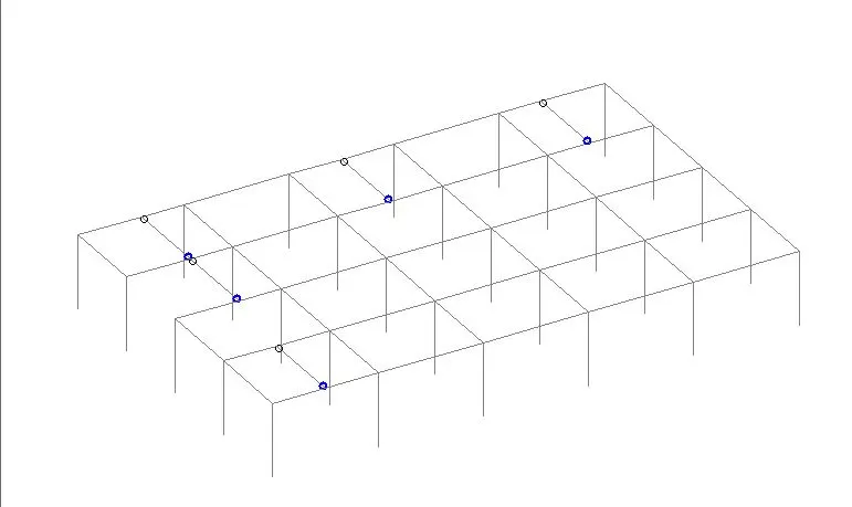
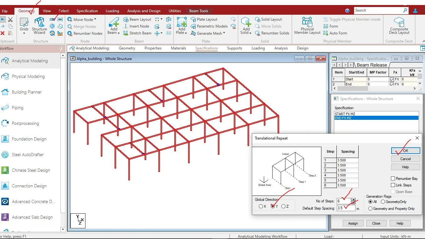
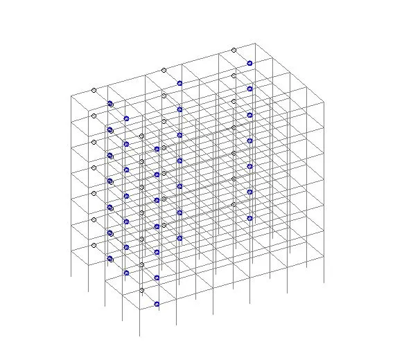
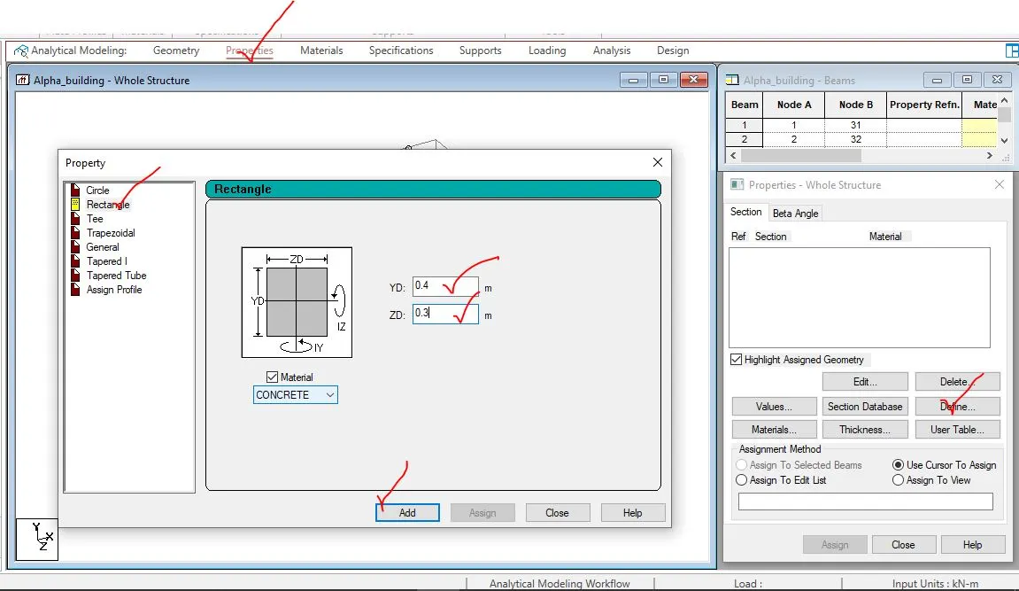
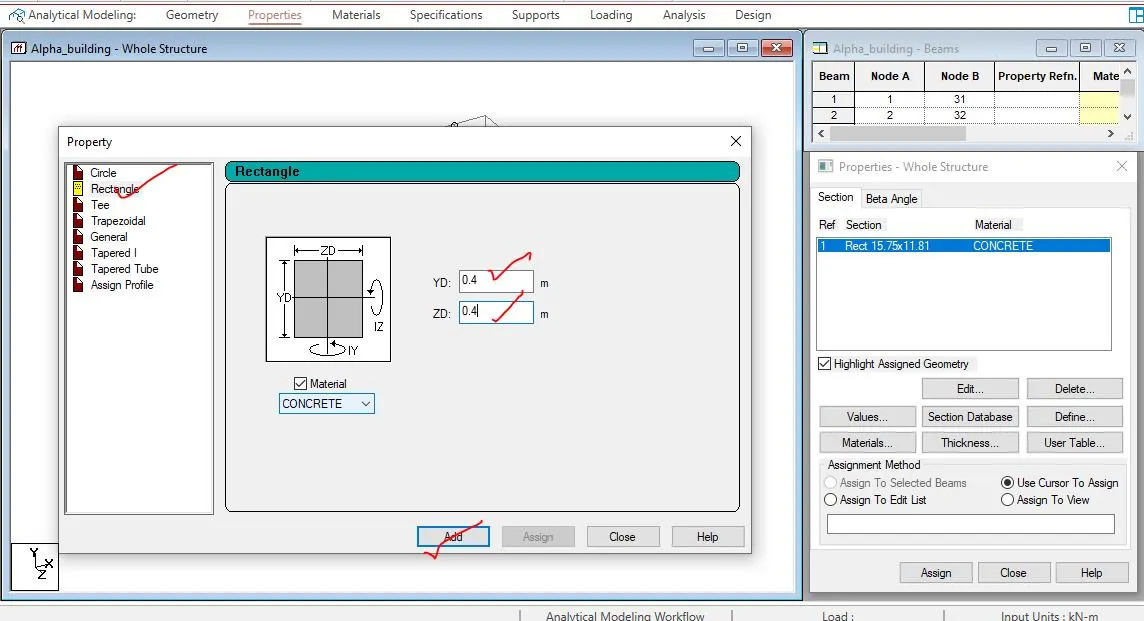
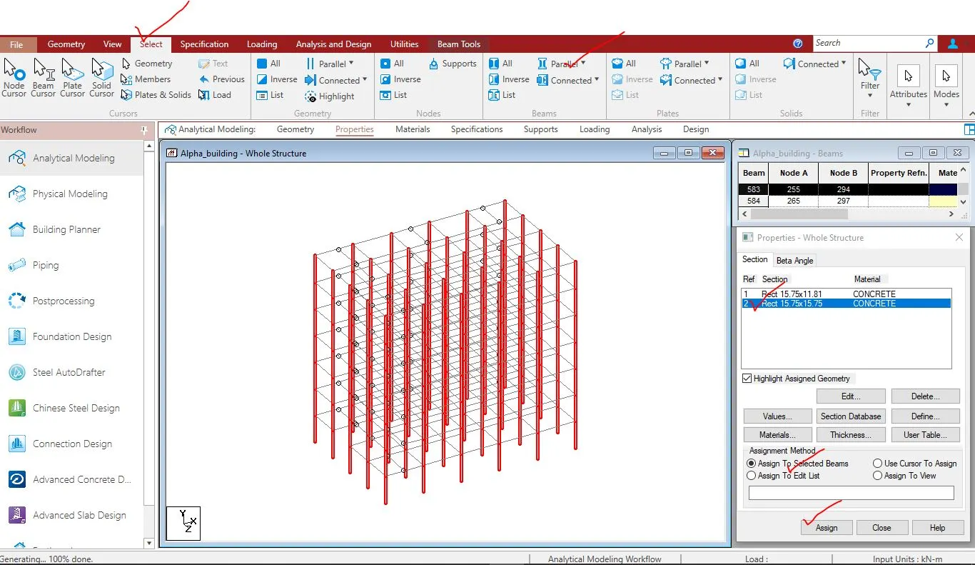
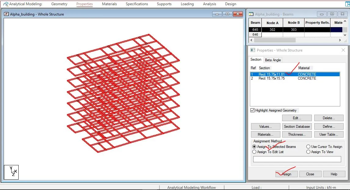
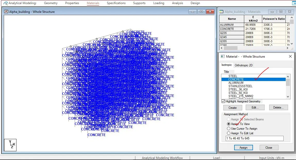
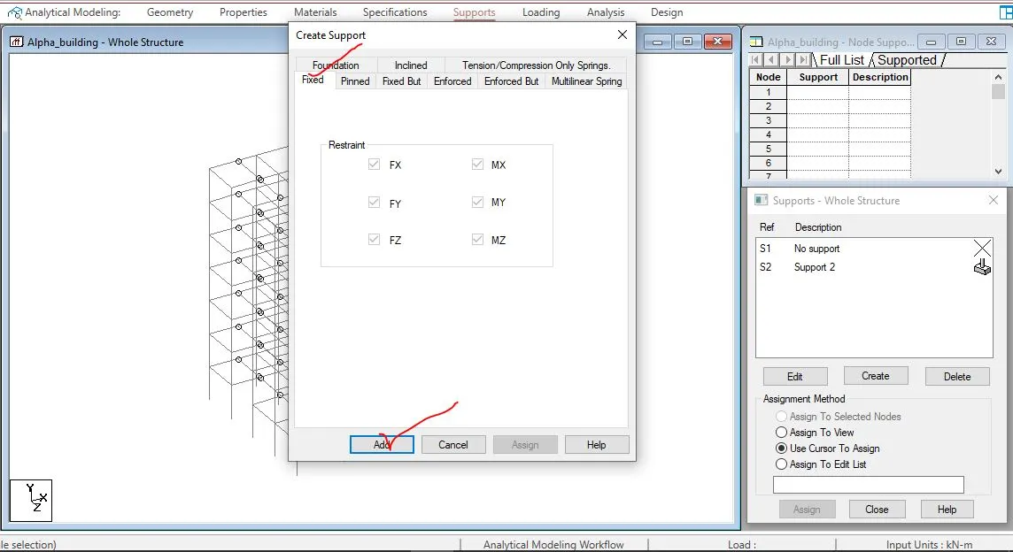
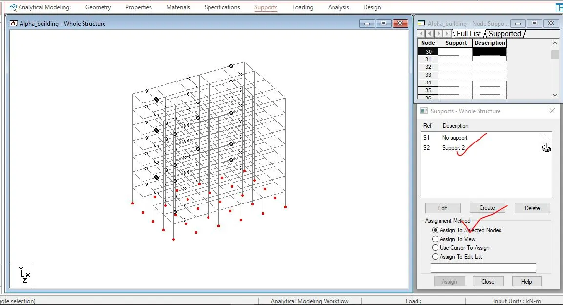
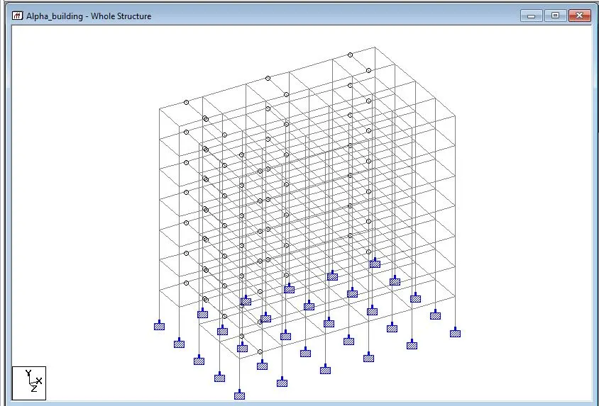
4.3 Results-
The file named as Alpha_building.std releated to the creation of the structural model using STAAD pro has been uploaded.
5.1 Preparing of DL, LL, WL and EQL load calculations as per IS 875 standards
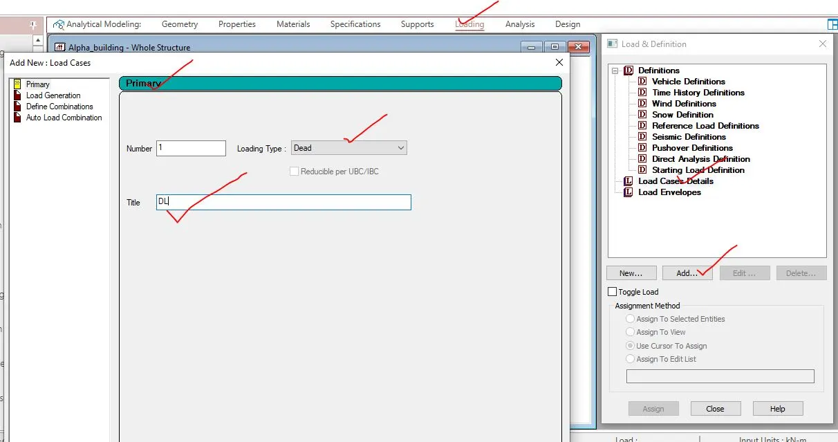
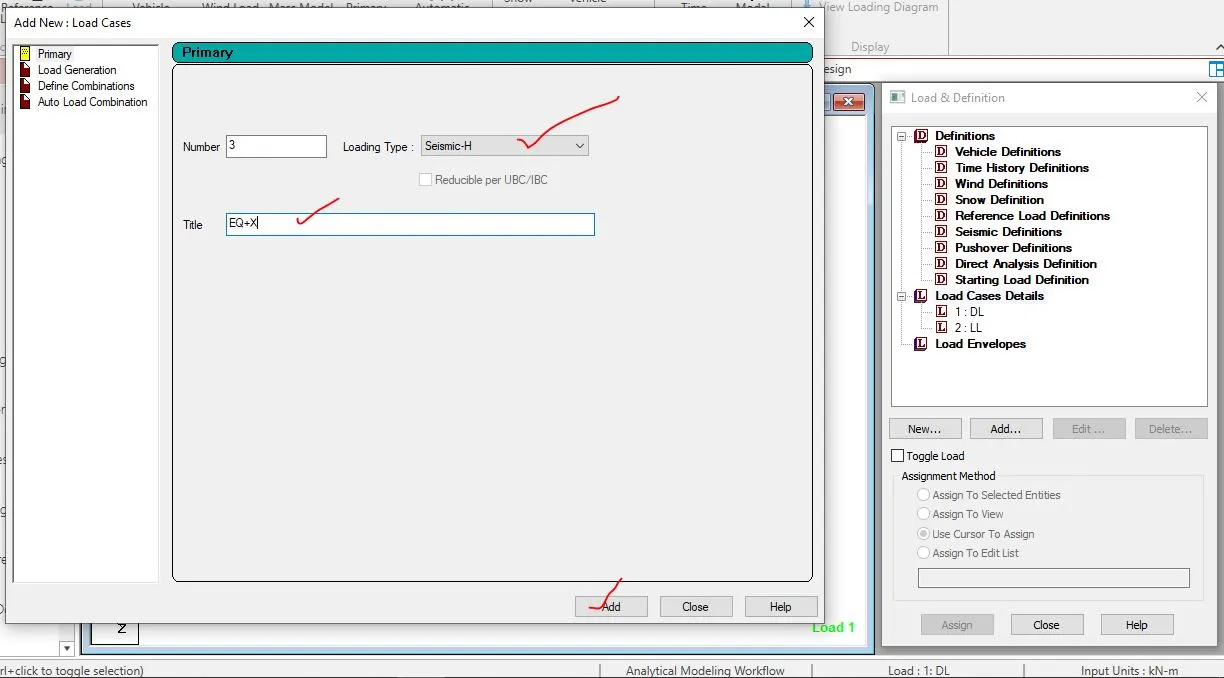
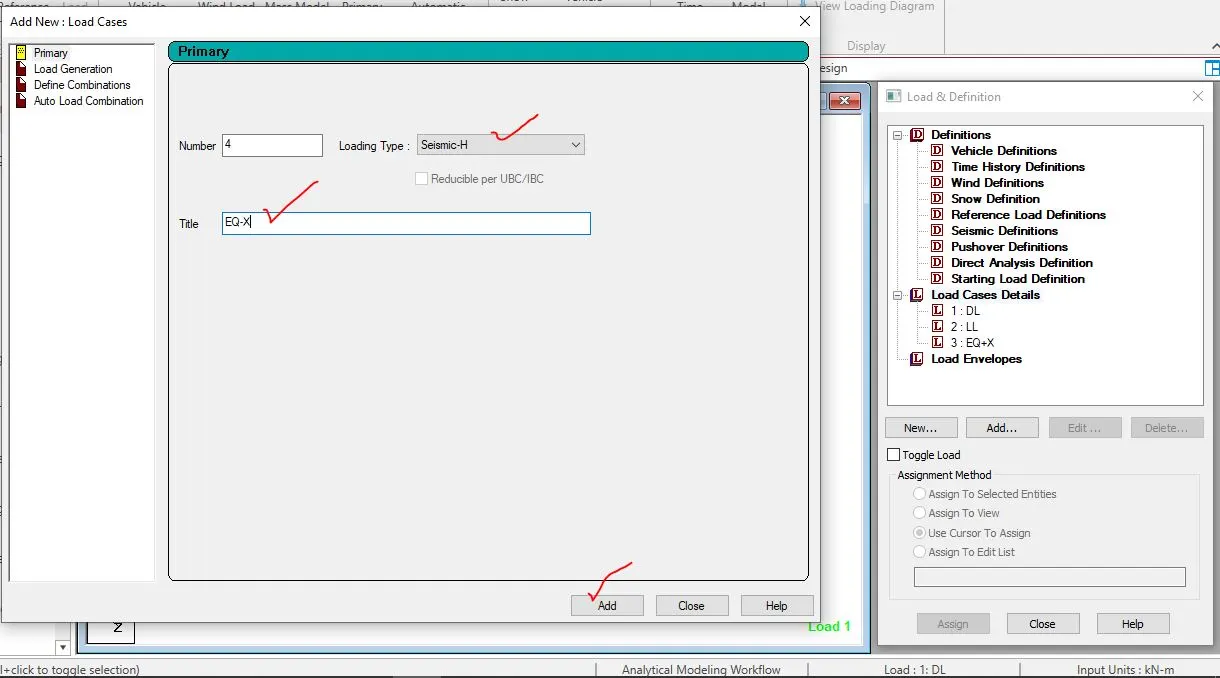
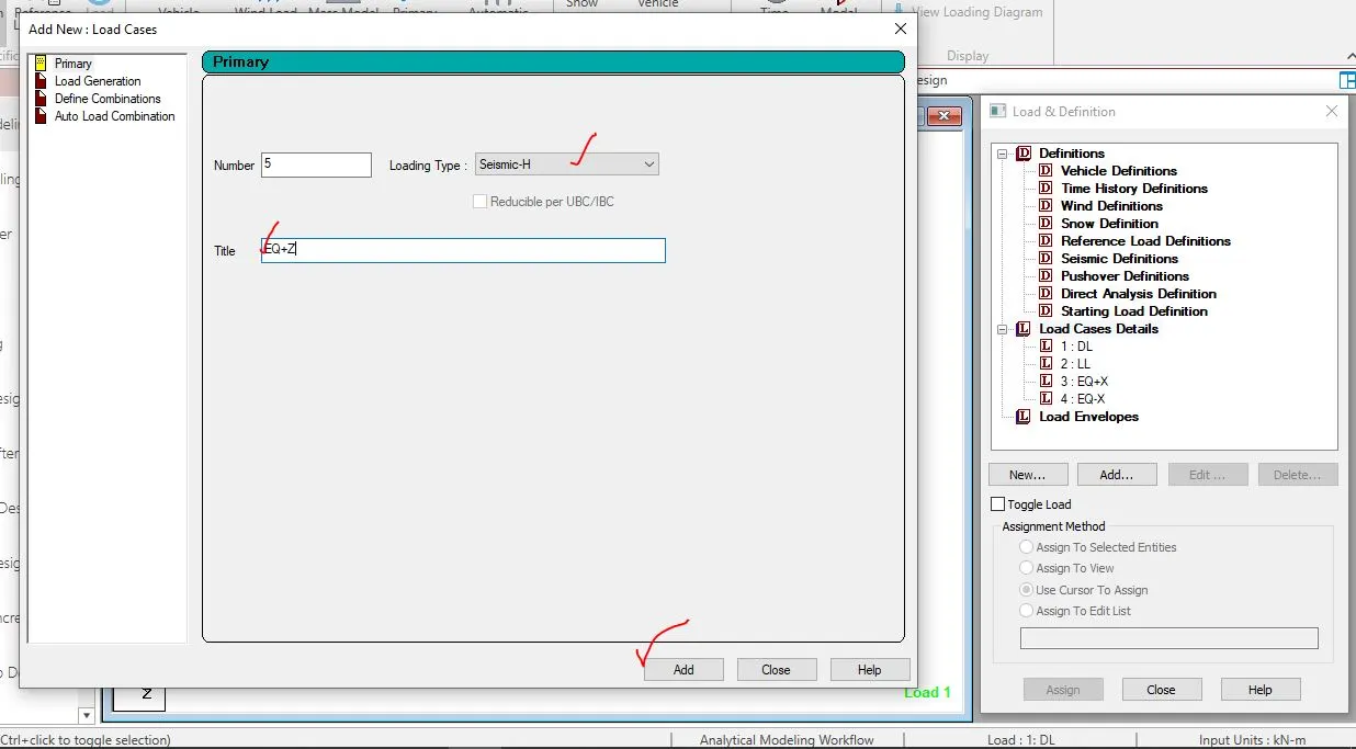
Step-1- After the creation, assigning of the material and support condition, then the loads i.e. live loads, dead loads, wind load and earthquake load has been created and assigned to the structure.
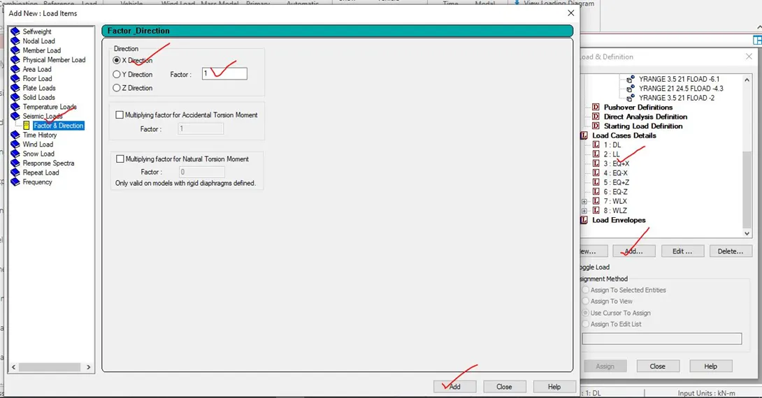
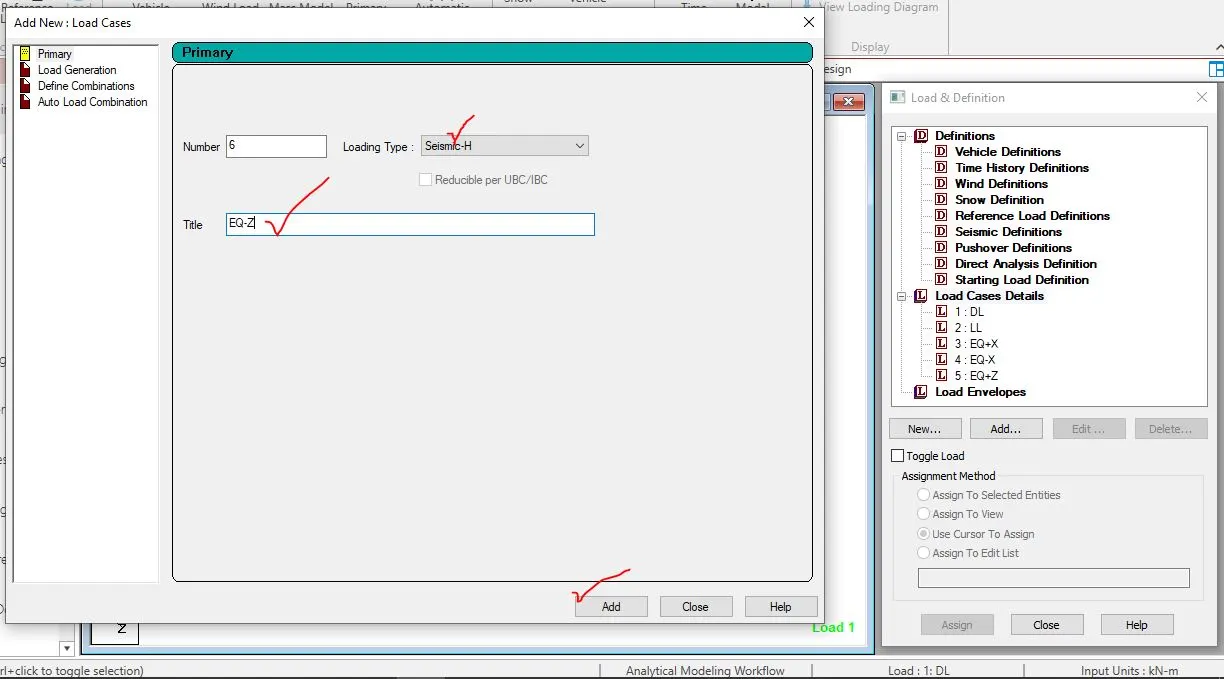
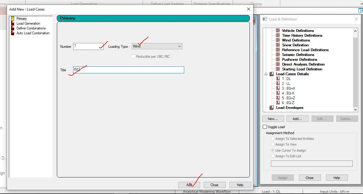
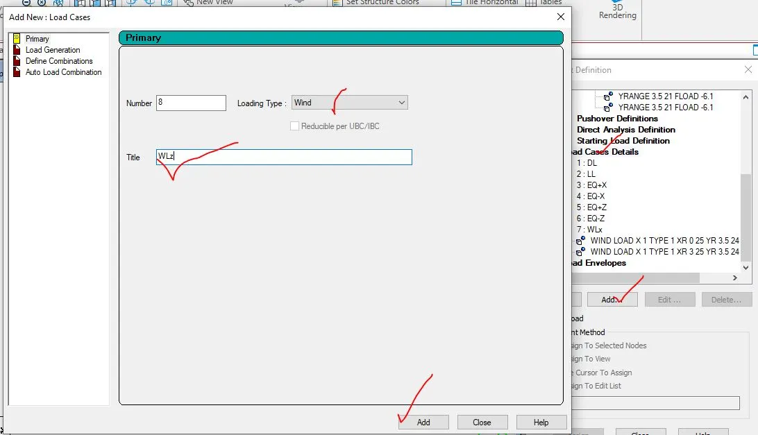
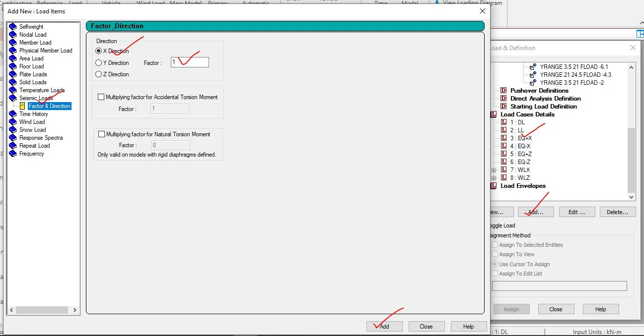
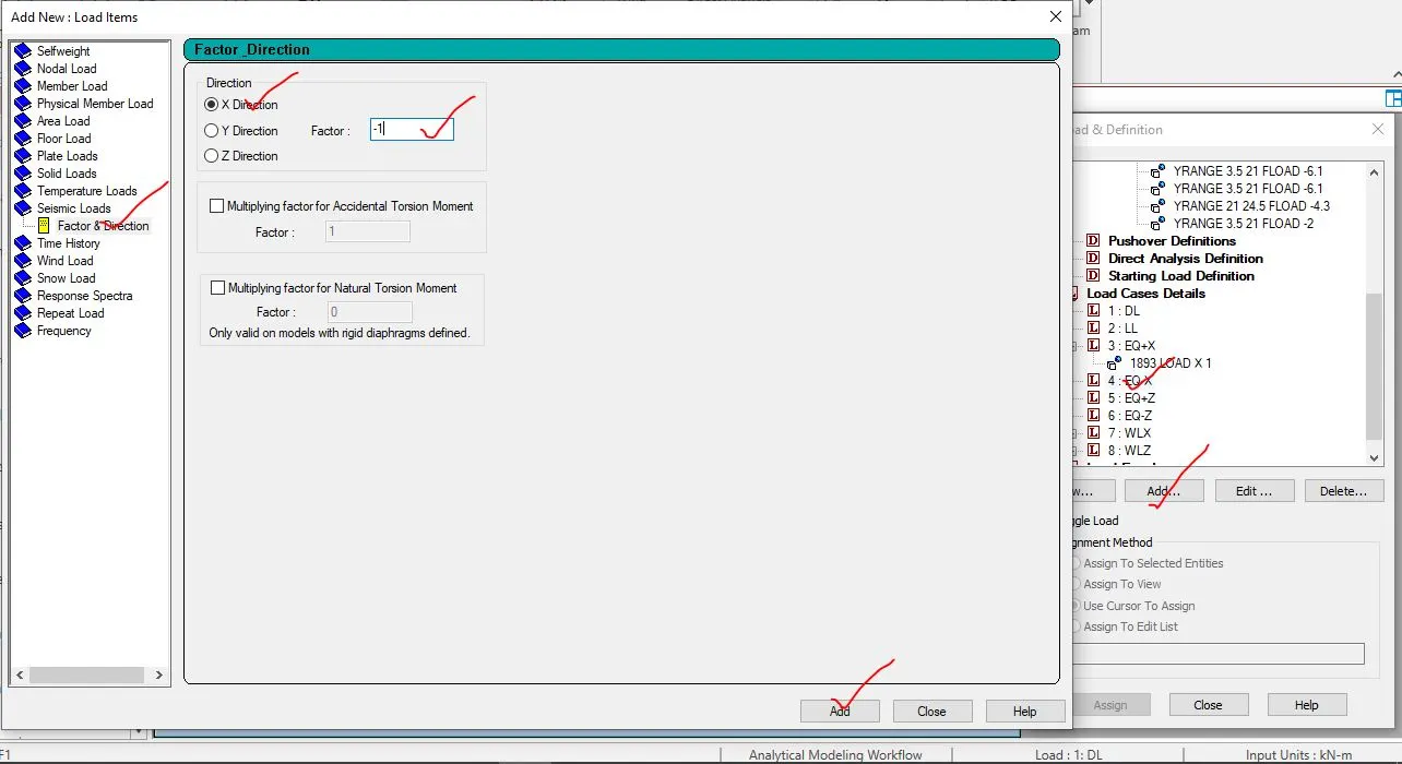
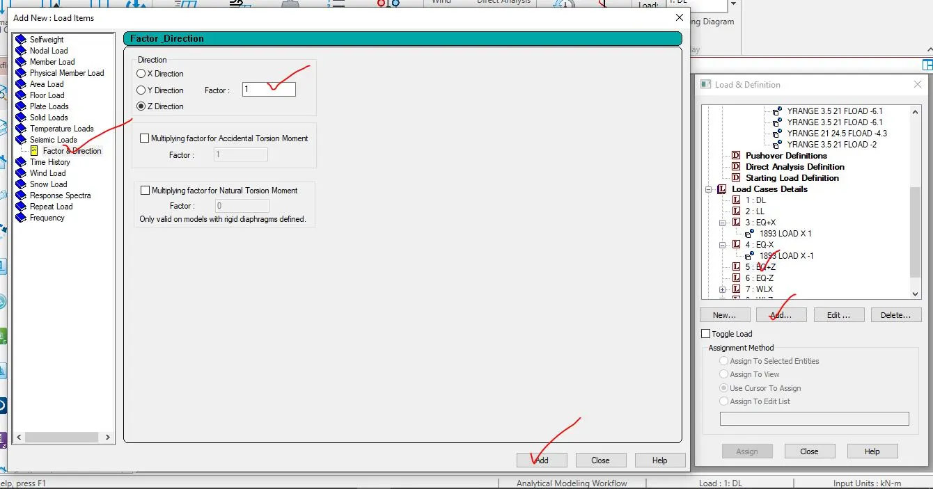
Step-2- The load cases of DL, LL and EQ in both direction has been defined as well as the WL has also been defined.
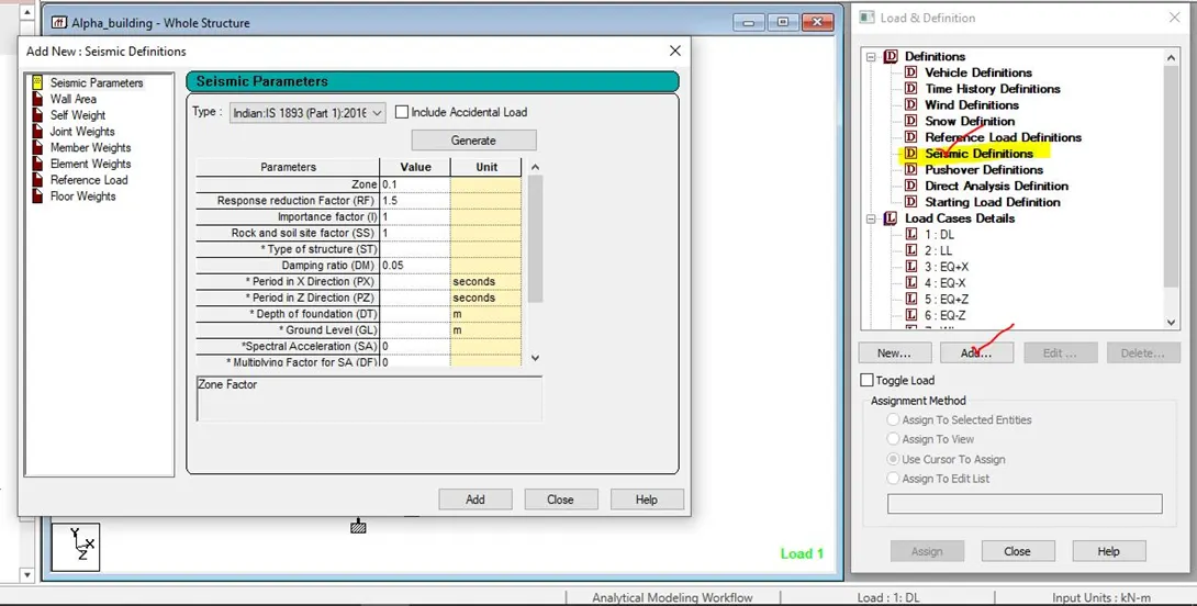
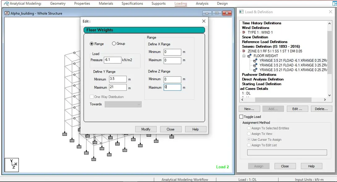
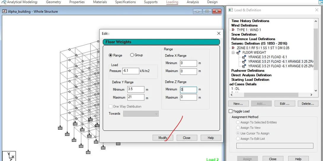
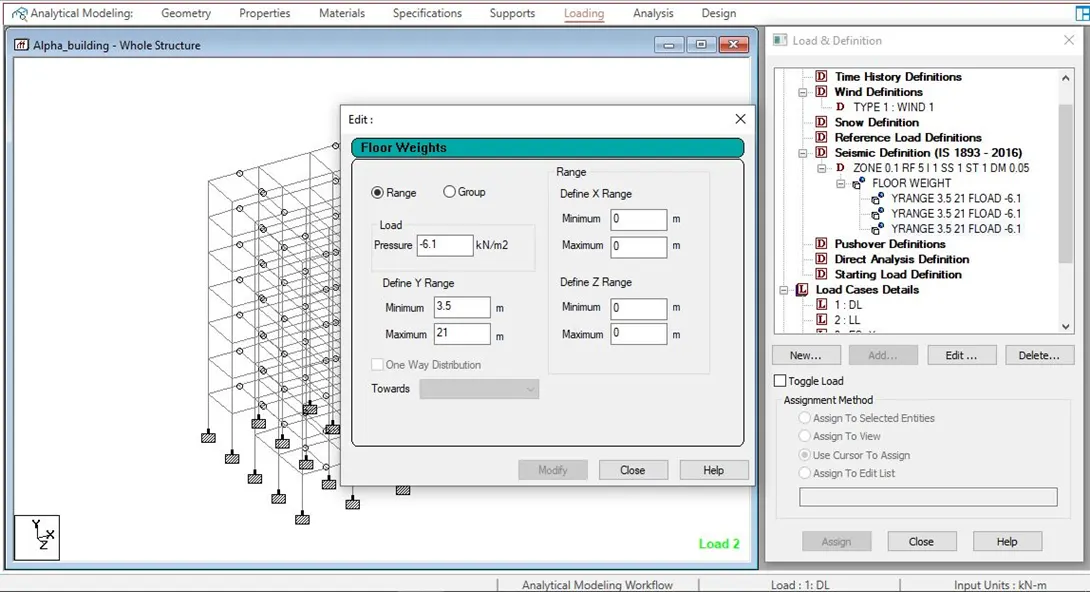
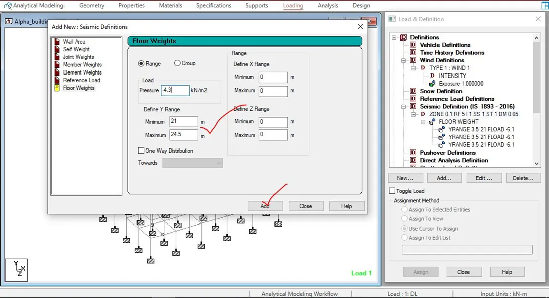
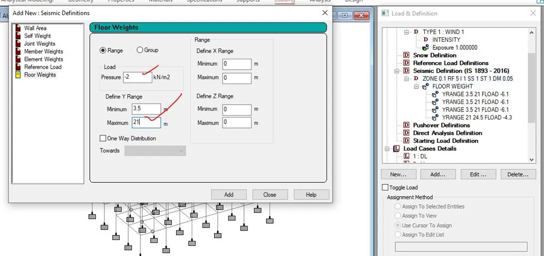
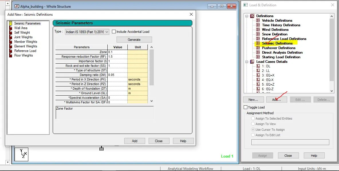
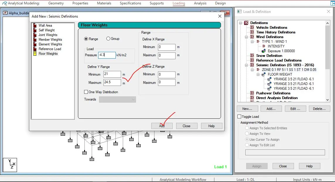
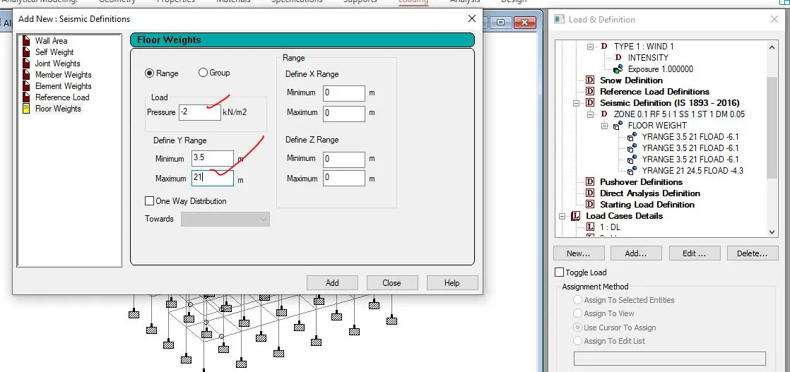
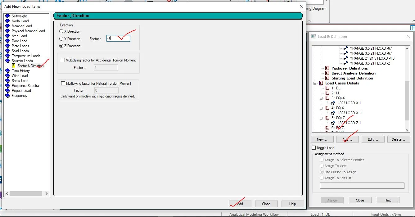
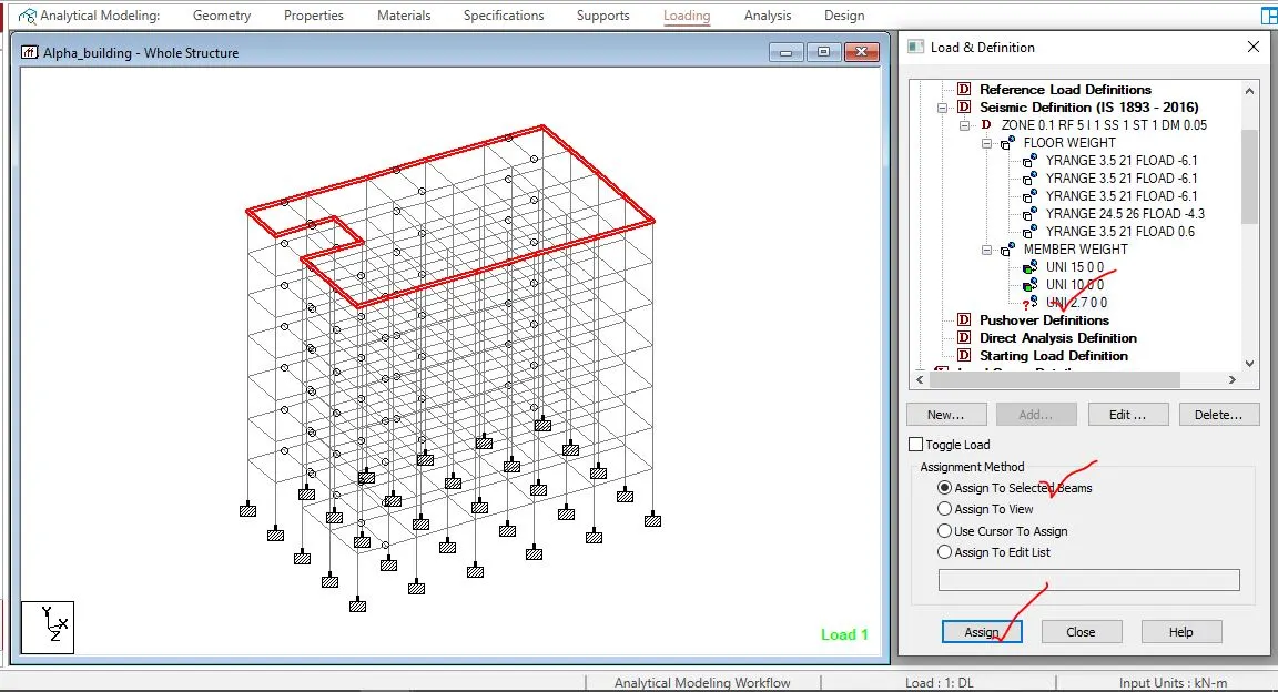
Step-3- Definition for earthquake load i.e. seismic definition has been added which has been shown below,
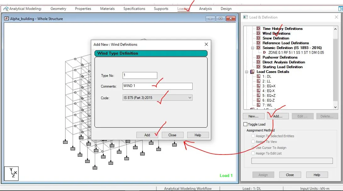
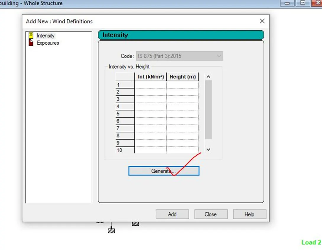
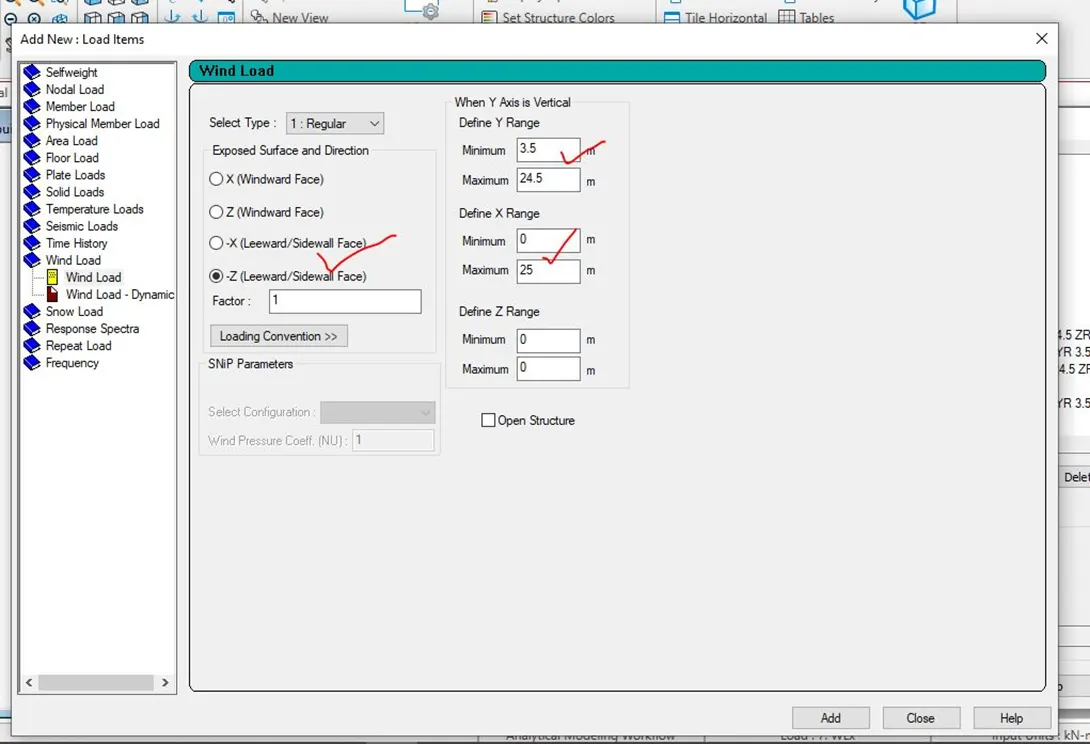
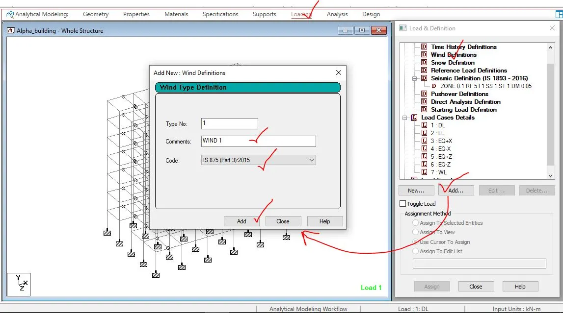
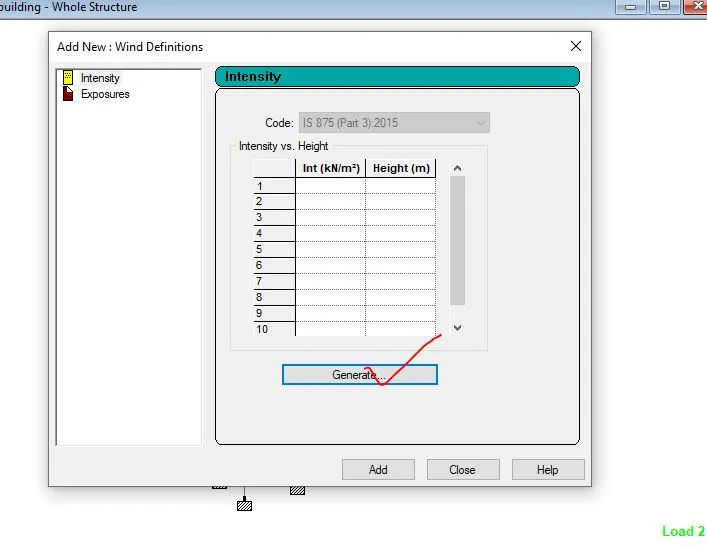
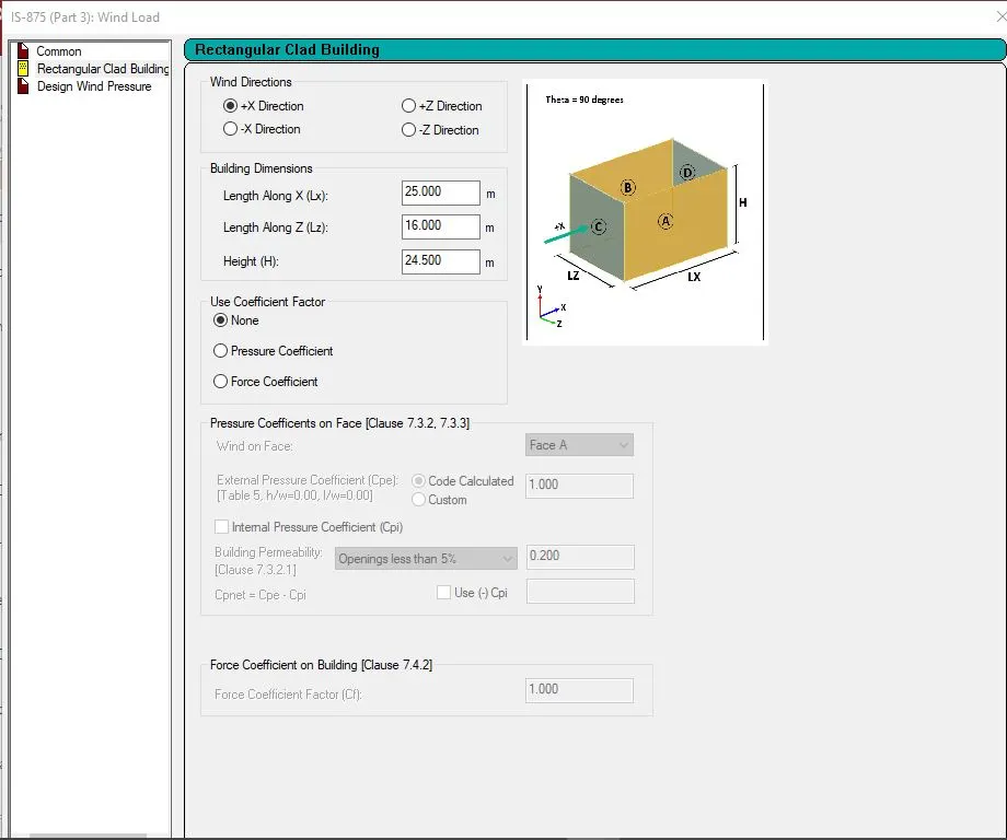
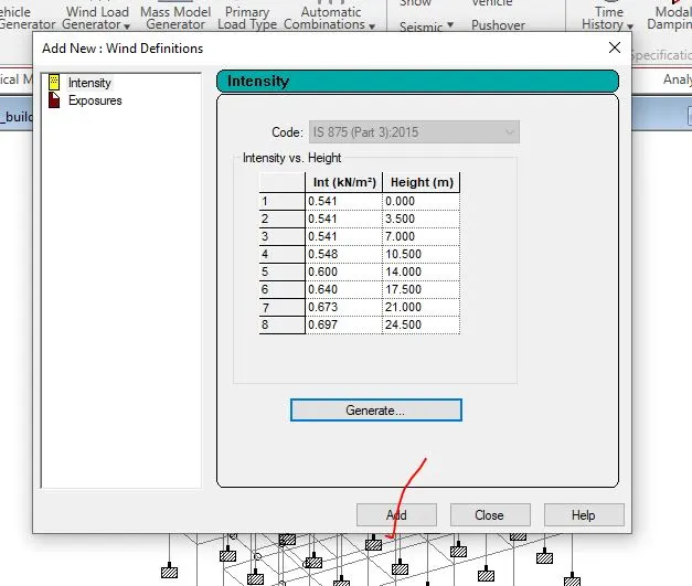
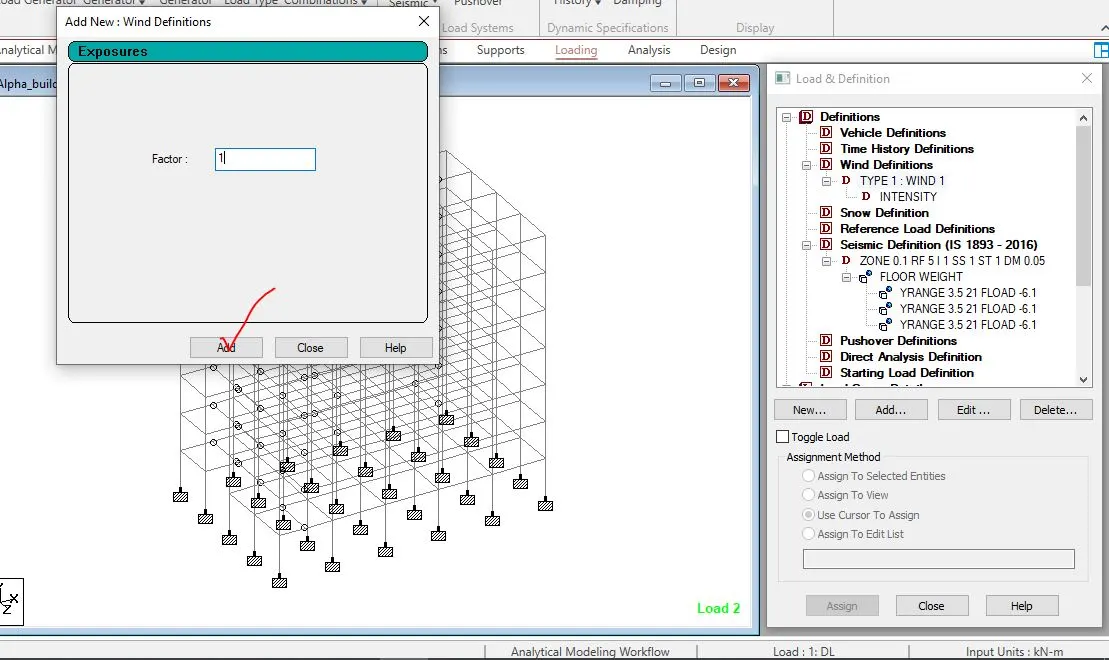
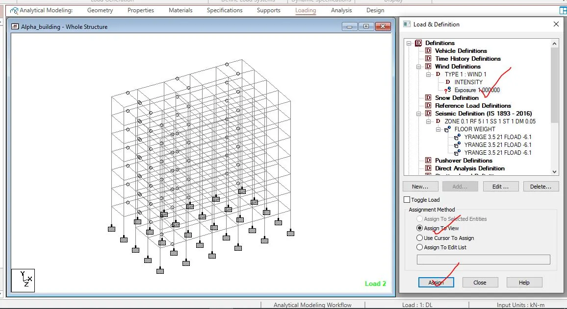
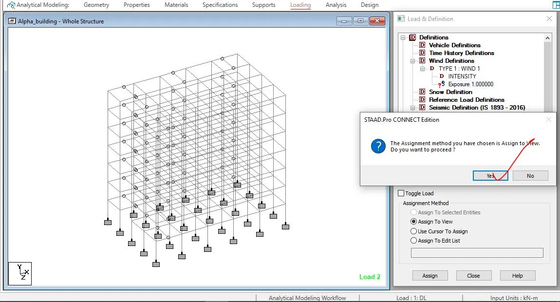
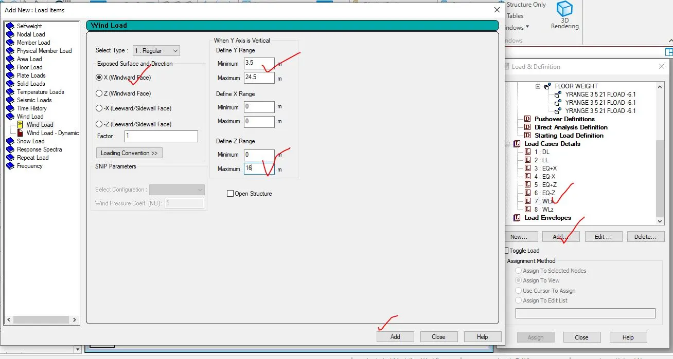
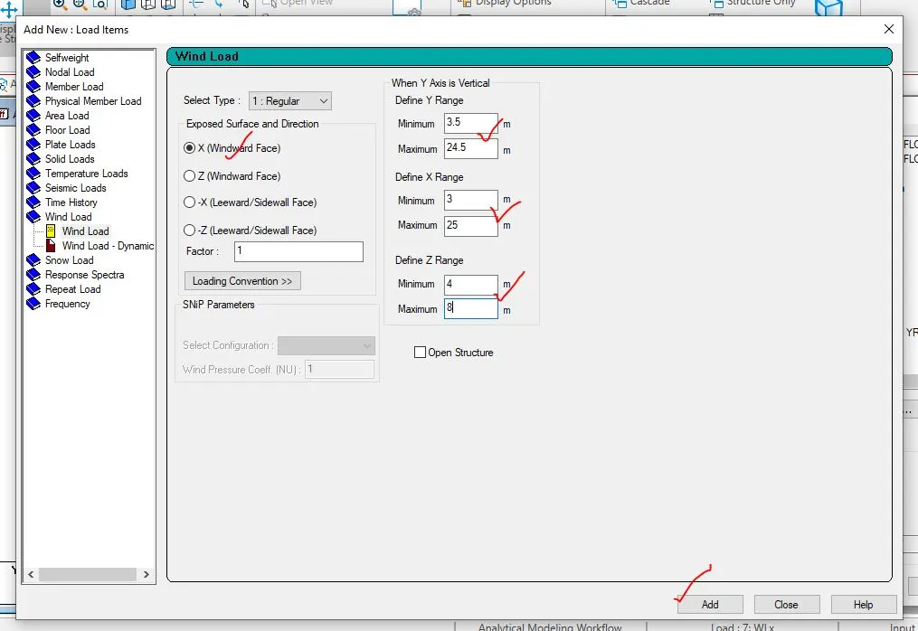
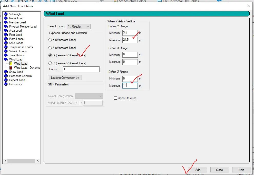
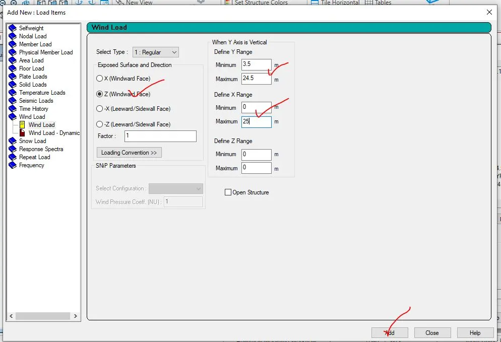
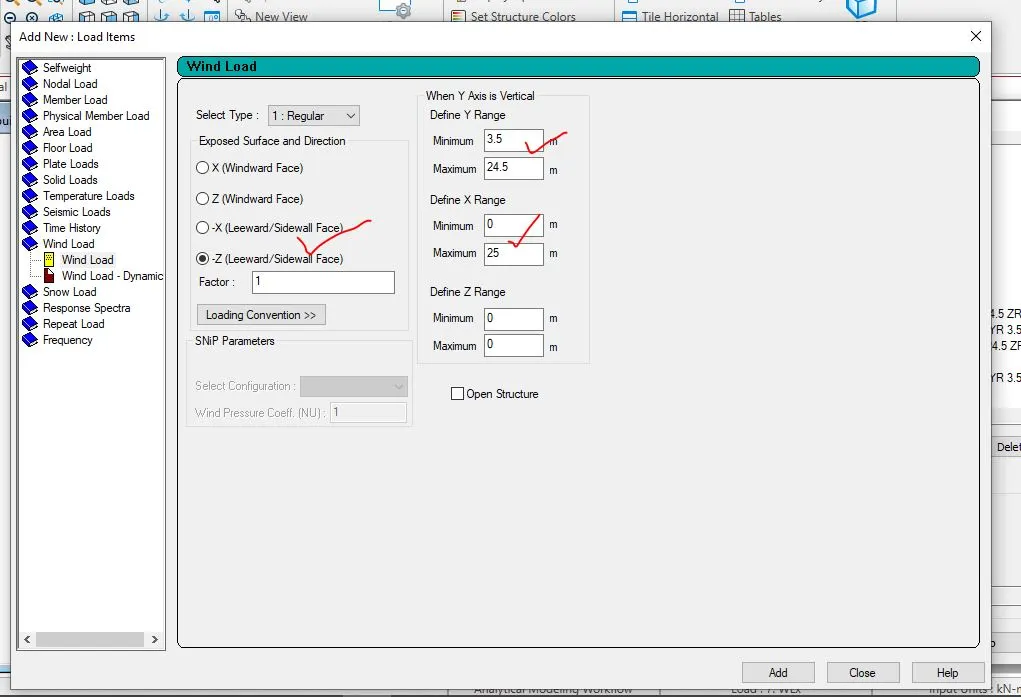
Step-4- in a same manner the wind definition has also been added which is also shown below,
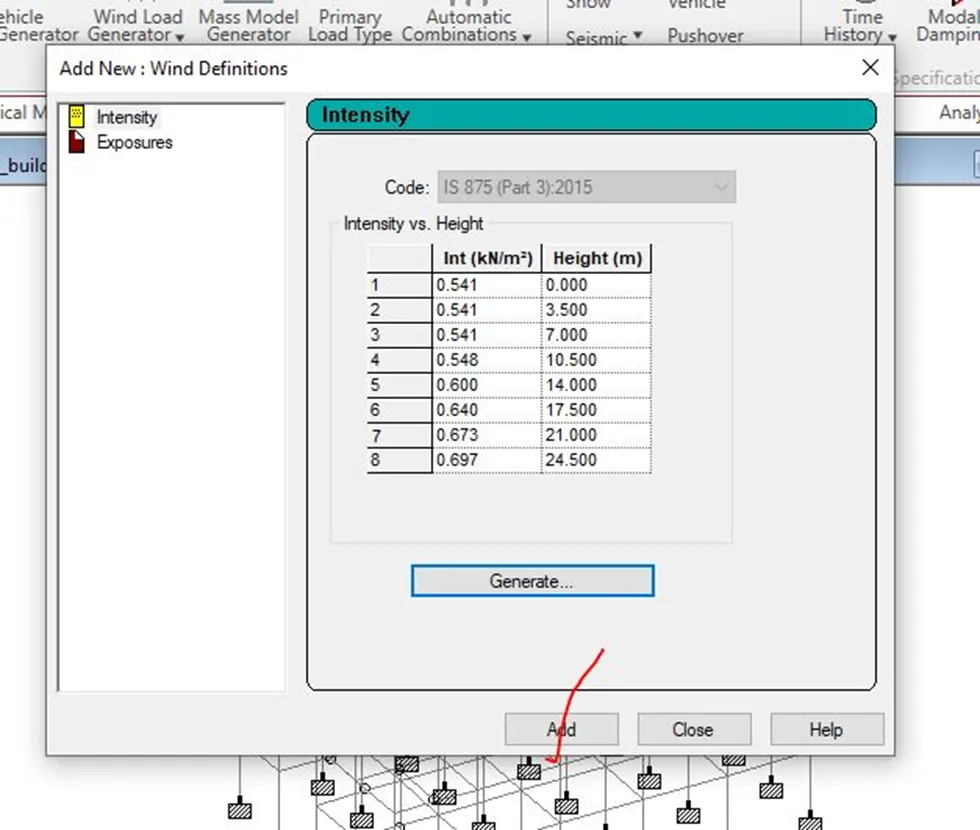
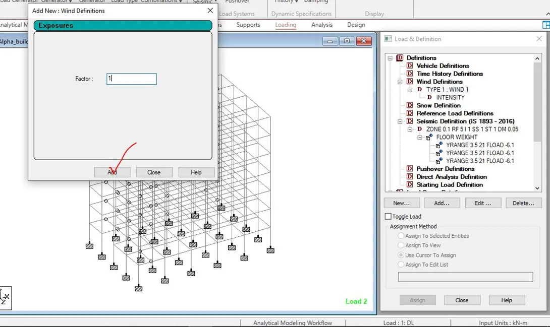
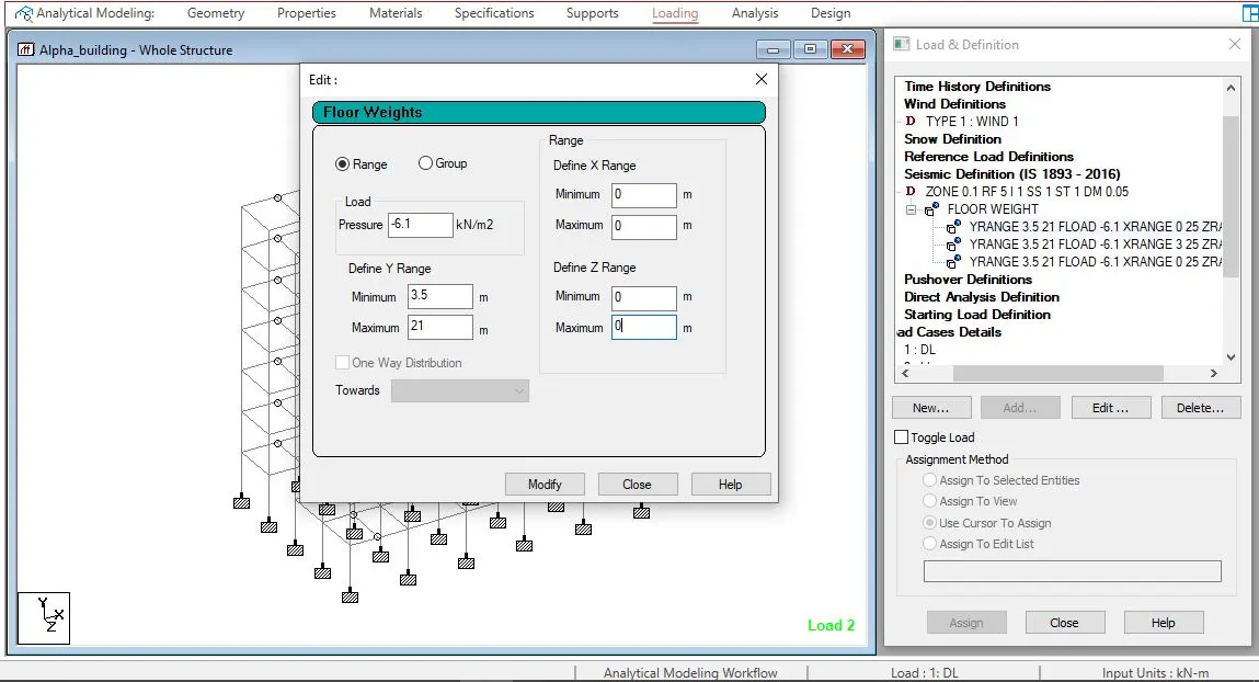
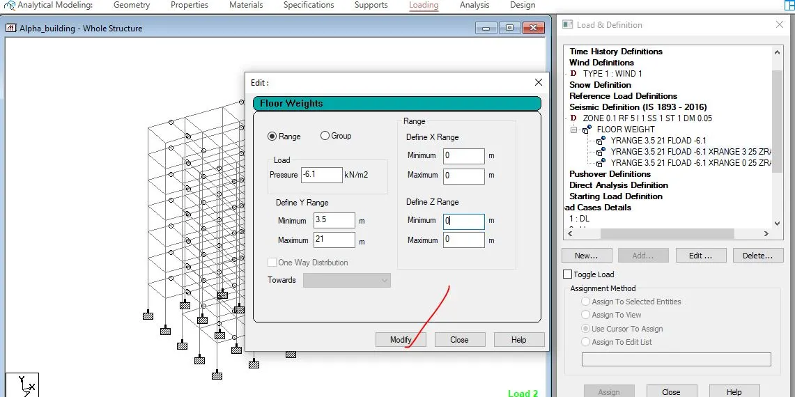
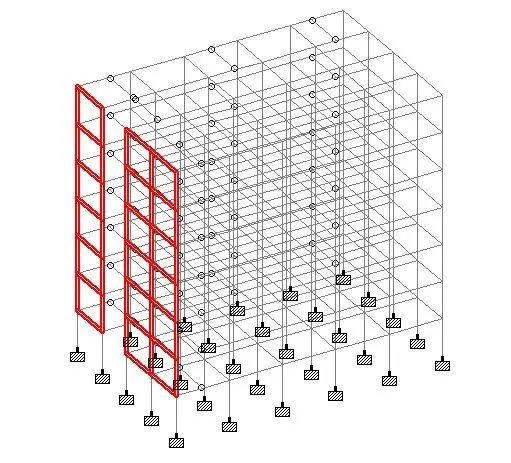
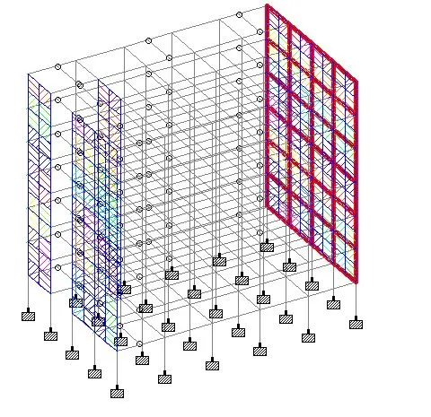
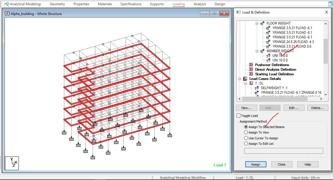
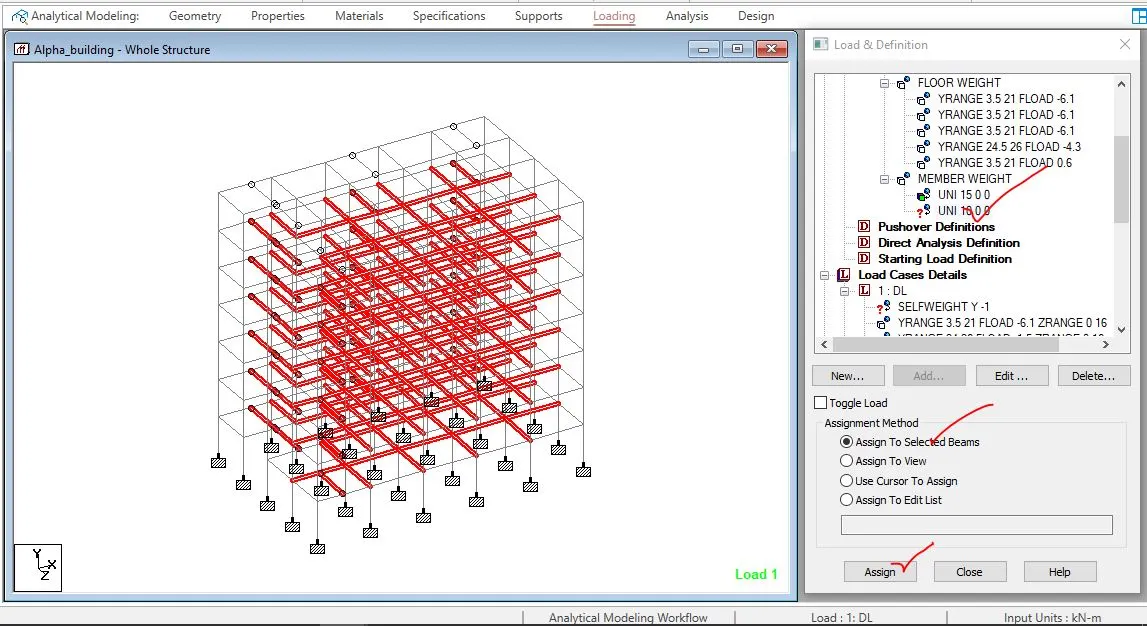
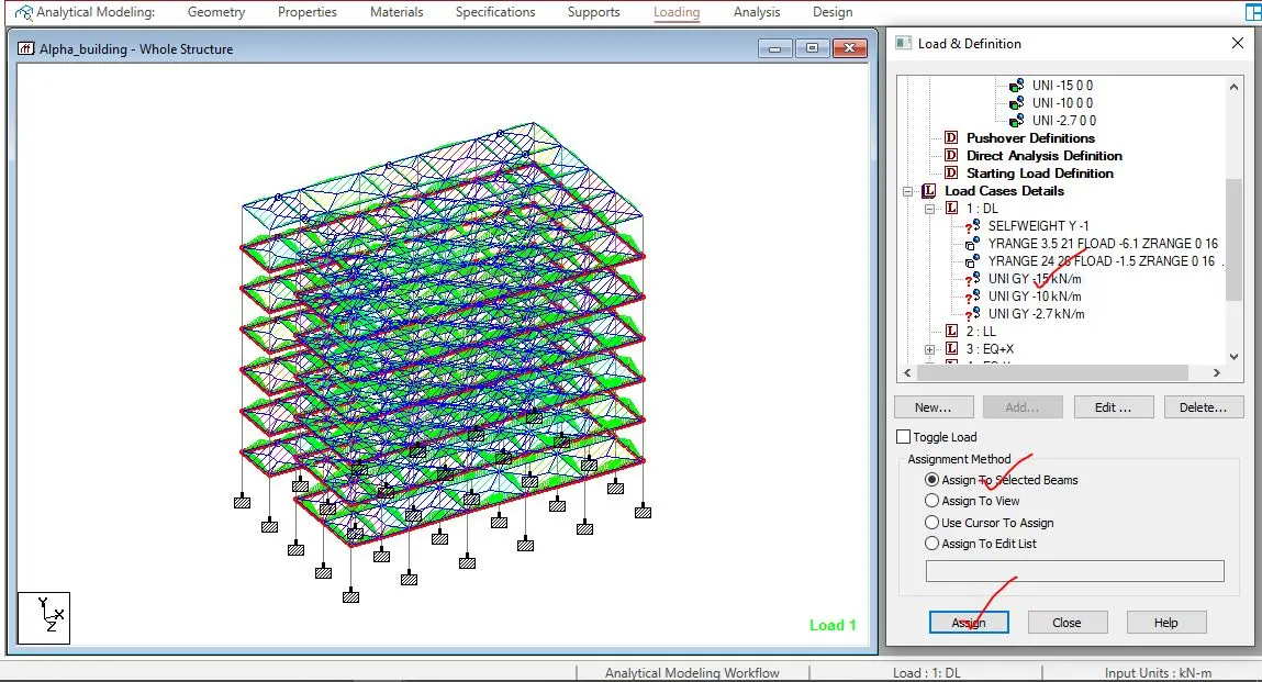
Step-5- after the addition of the definition of the wind and seismic, the lateral loads has been defined and assigned to the structure, which is shown below,
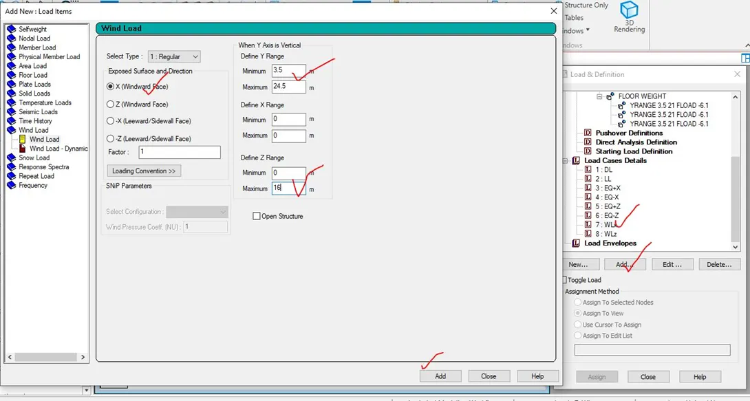
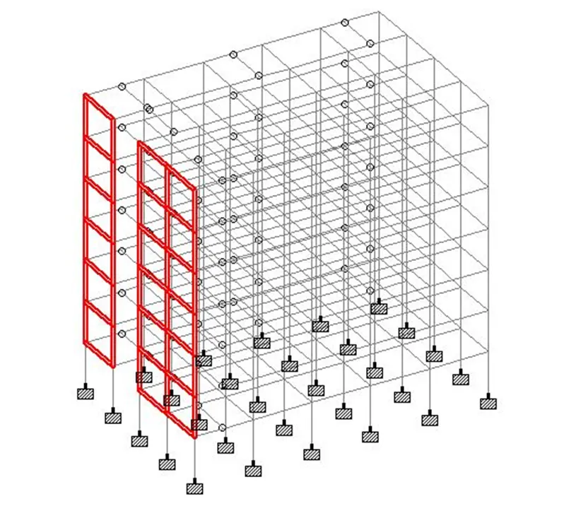
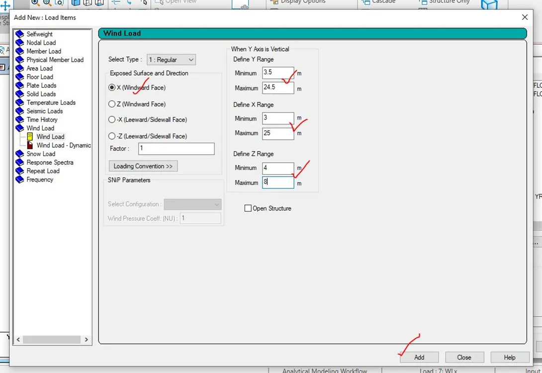
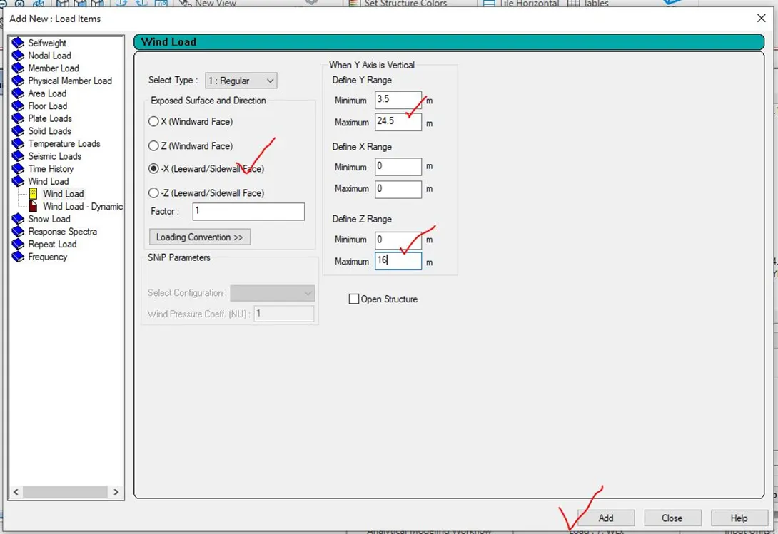
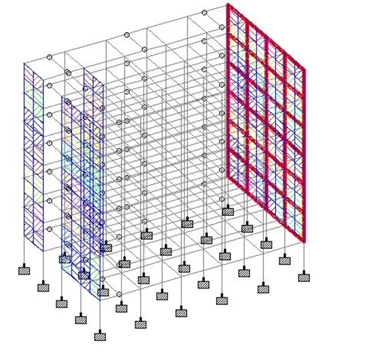
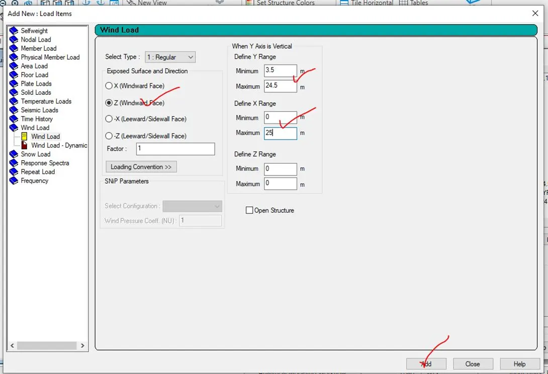
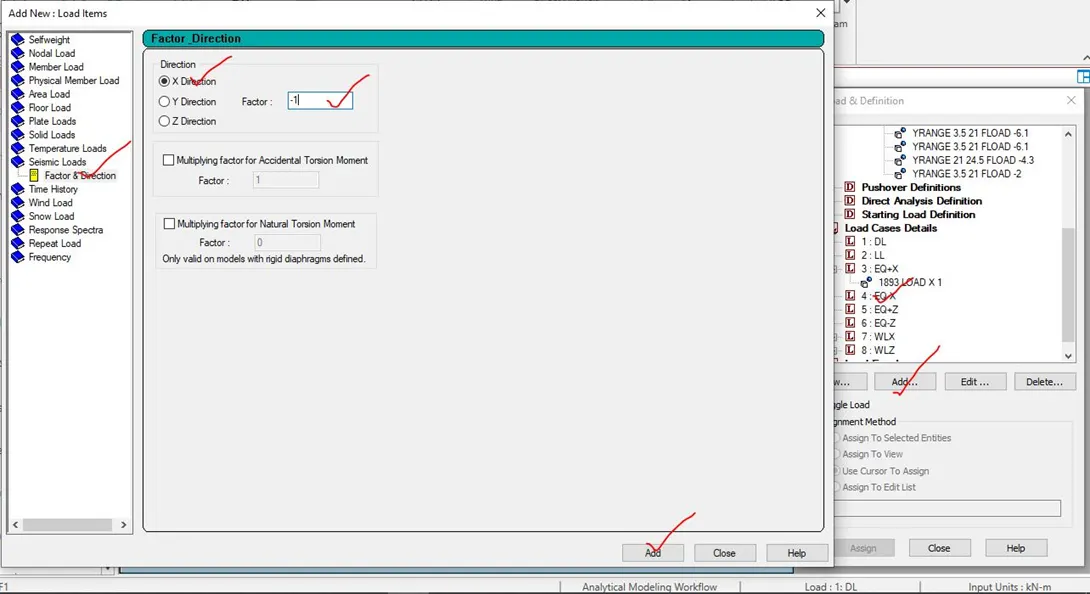
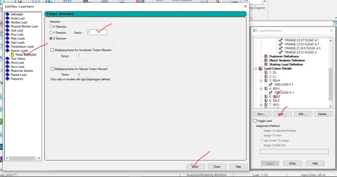
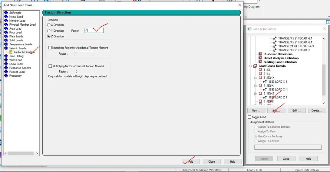
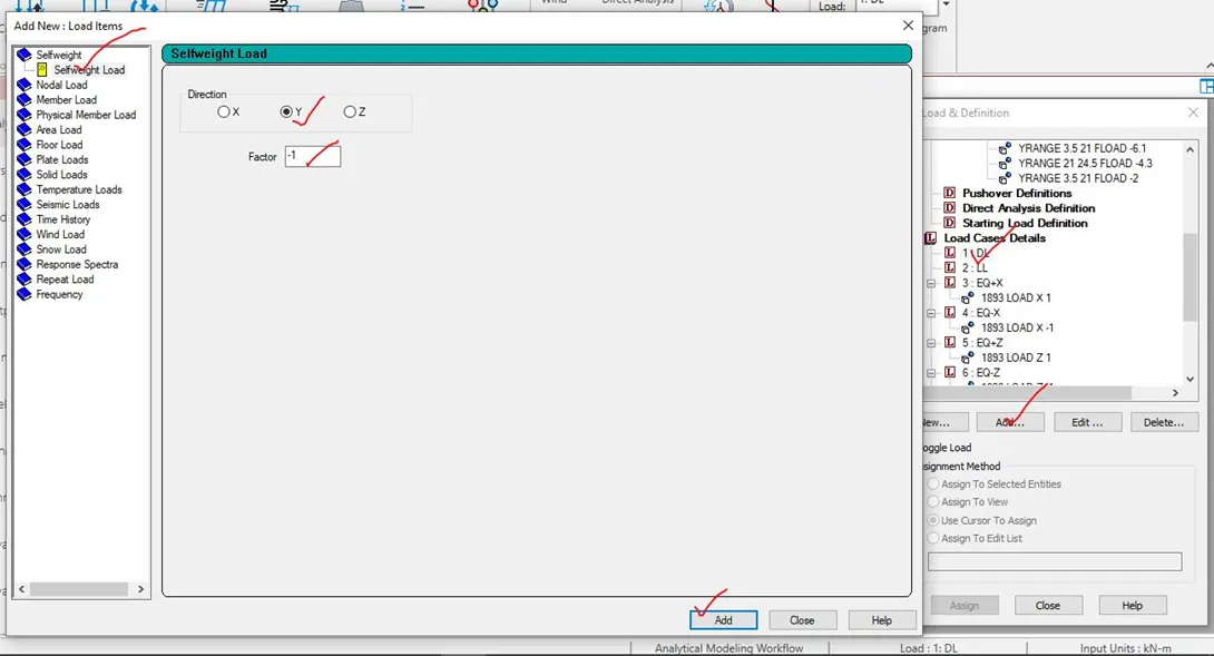
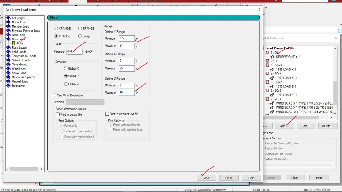
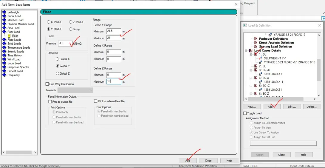
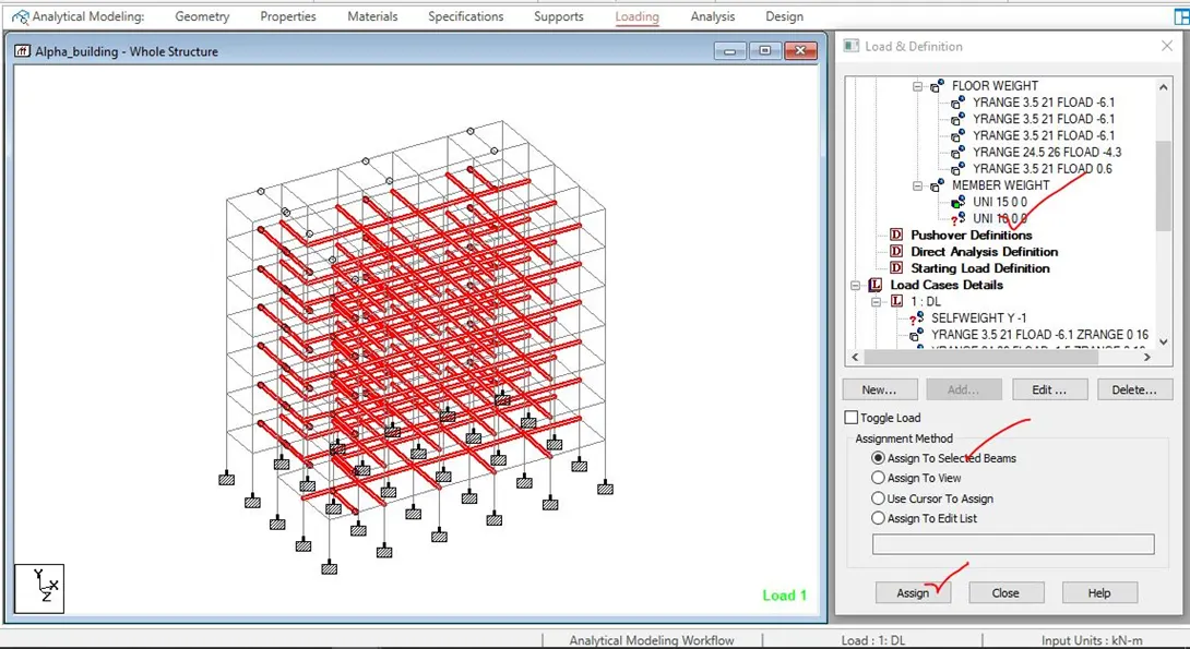
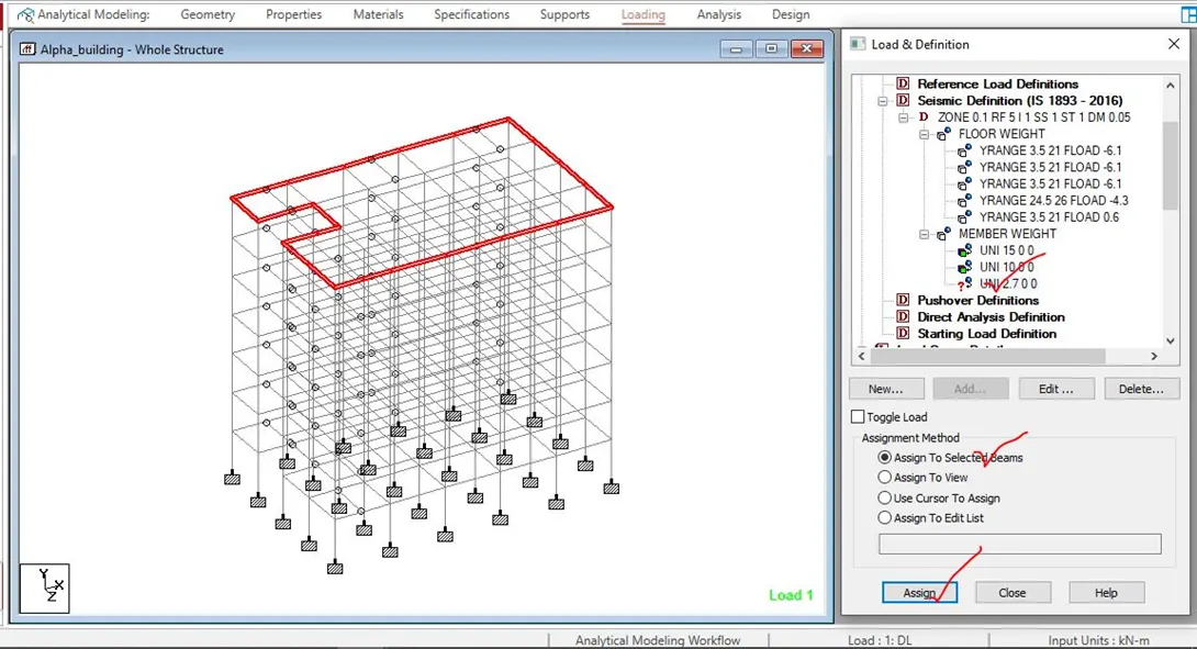
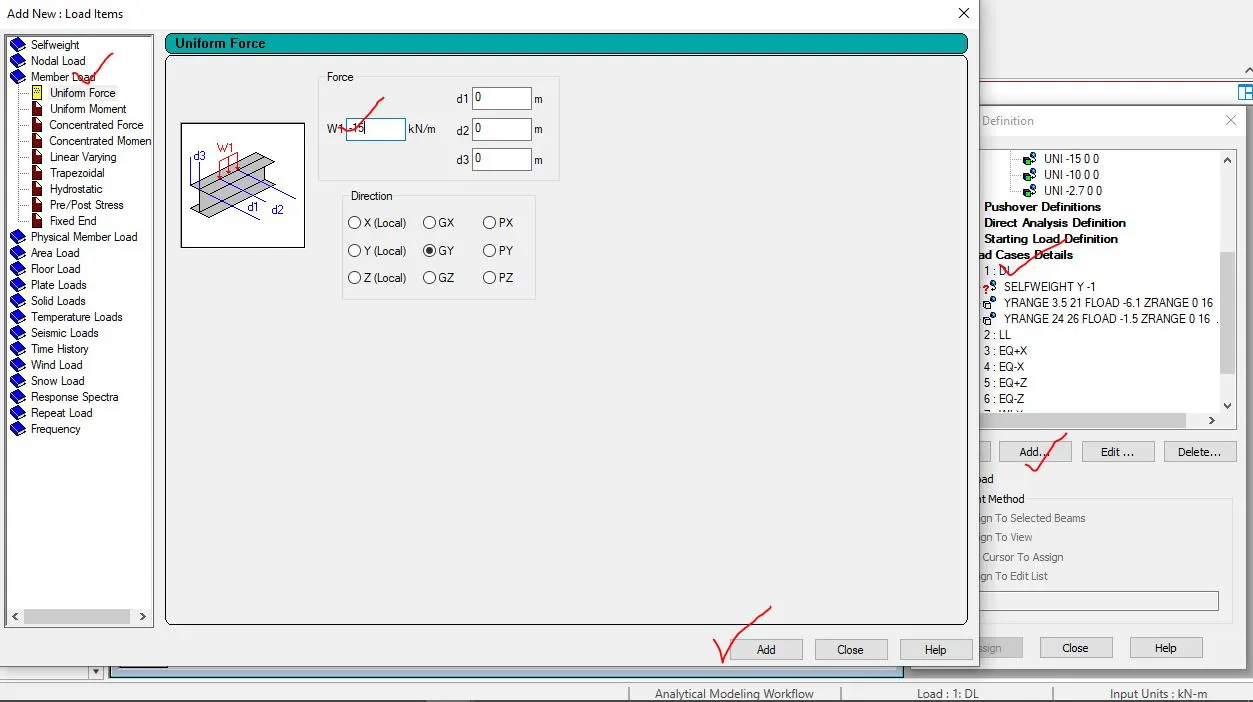
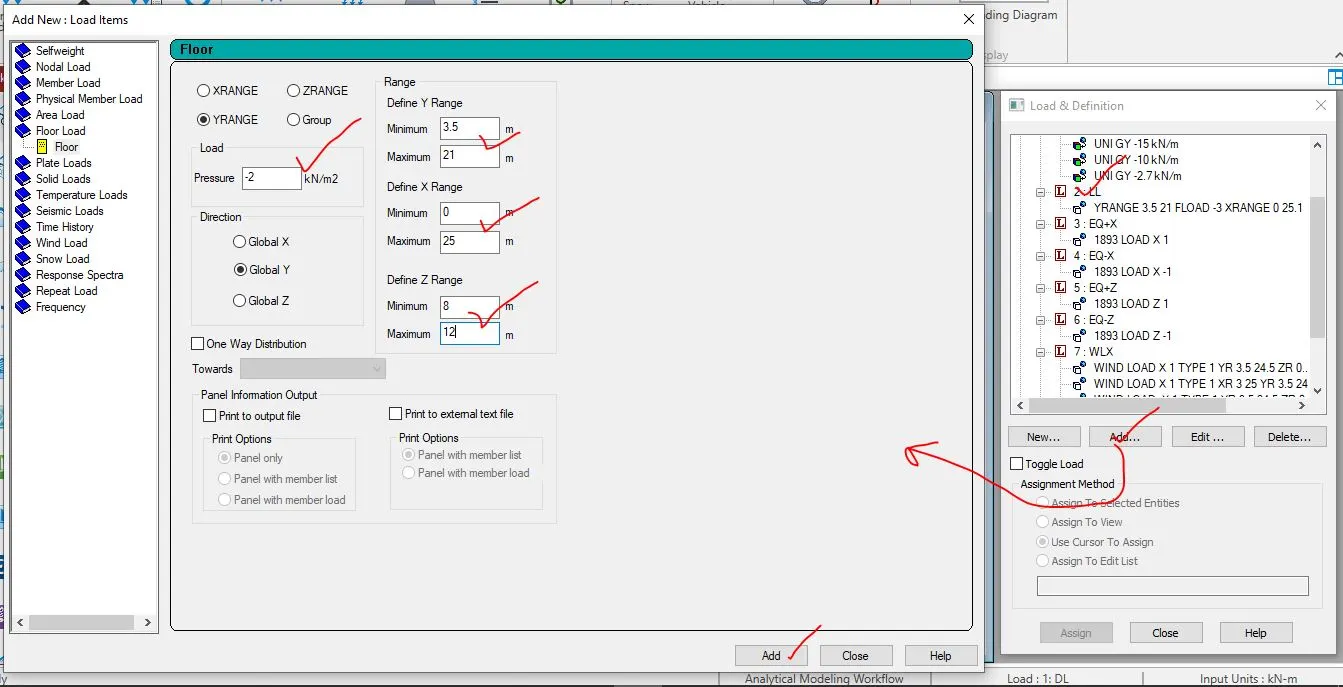
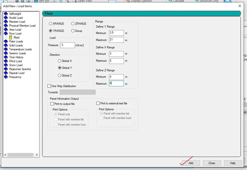
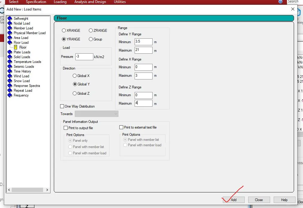
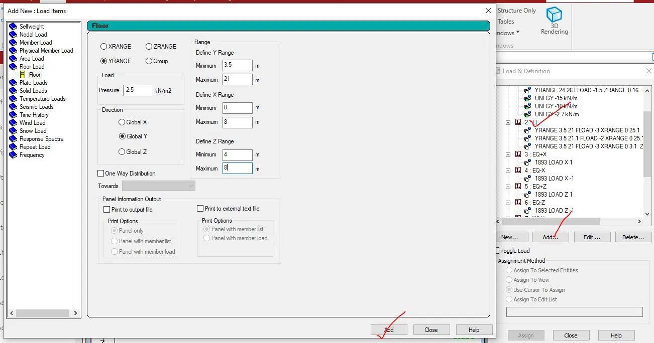
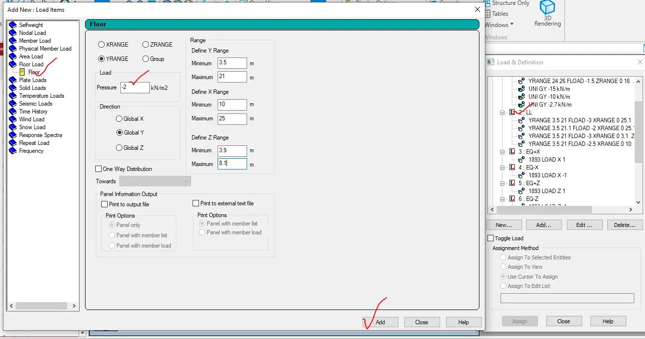
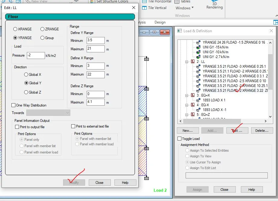
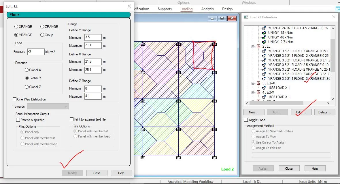
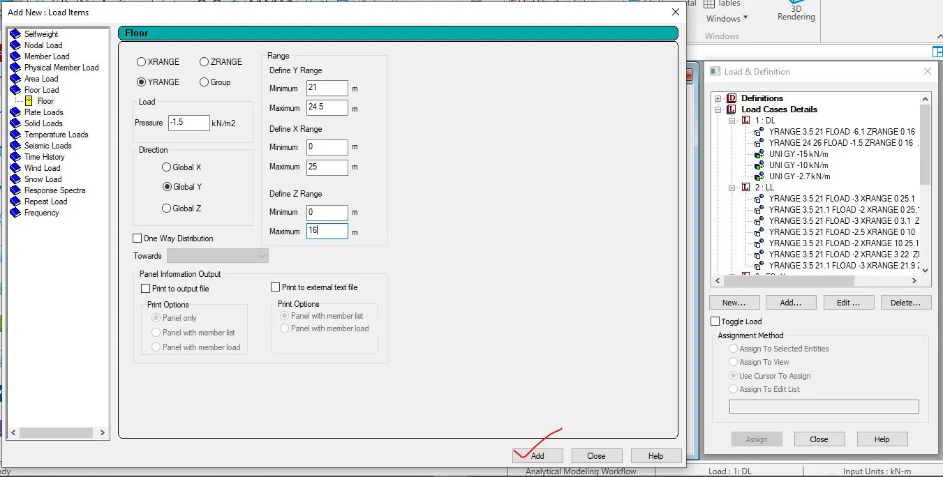
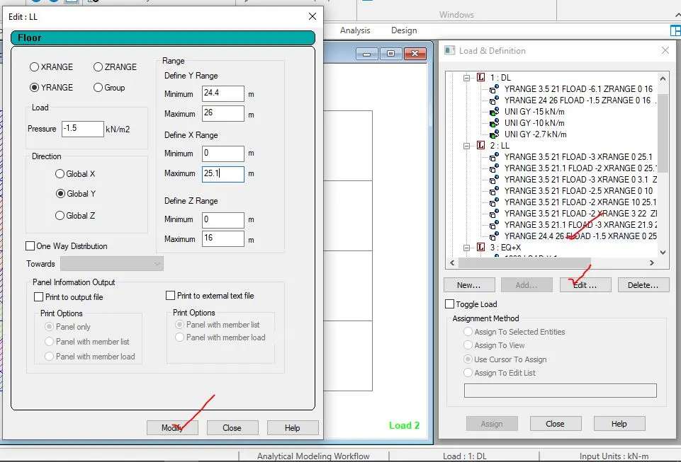
Step-6- Then the dead load and live loads according to the IS 875 has been defined and assigned as the location, which has been shown below,
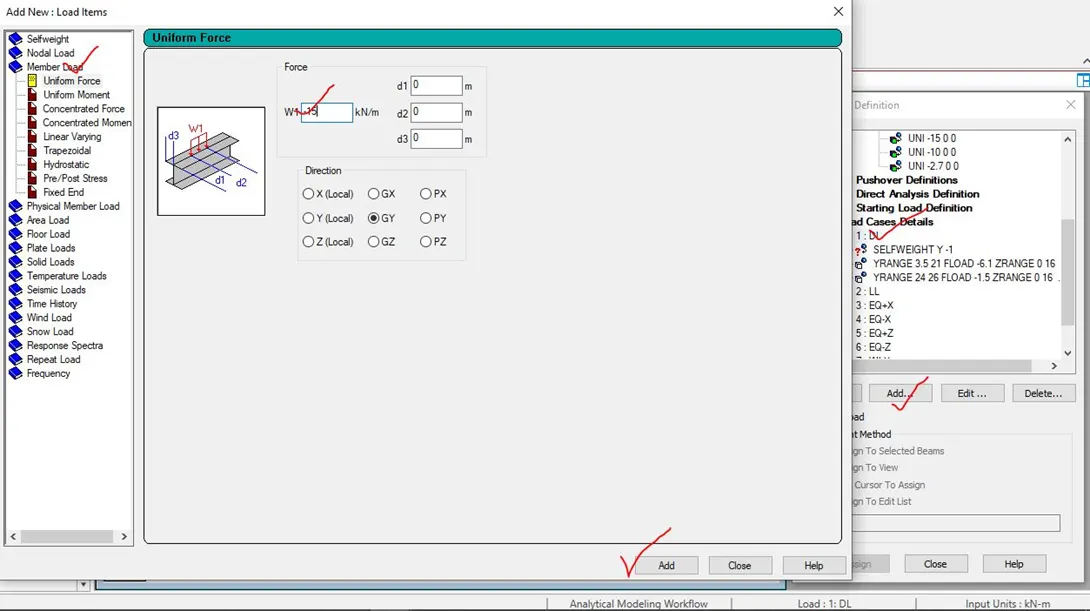
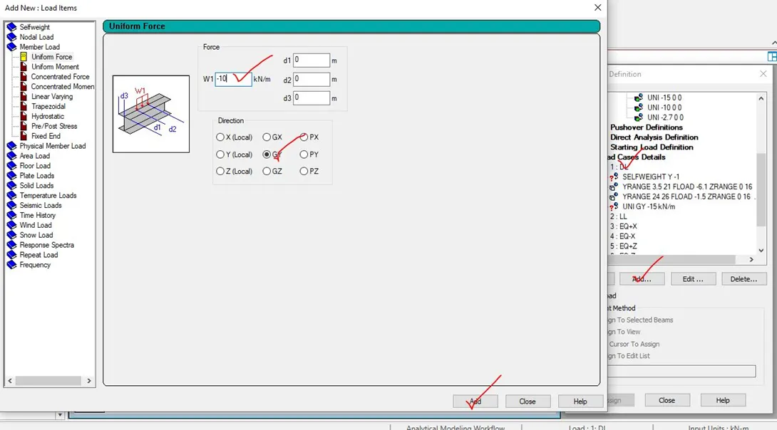
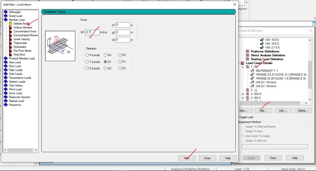
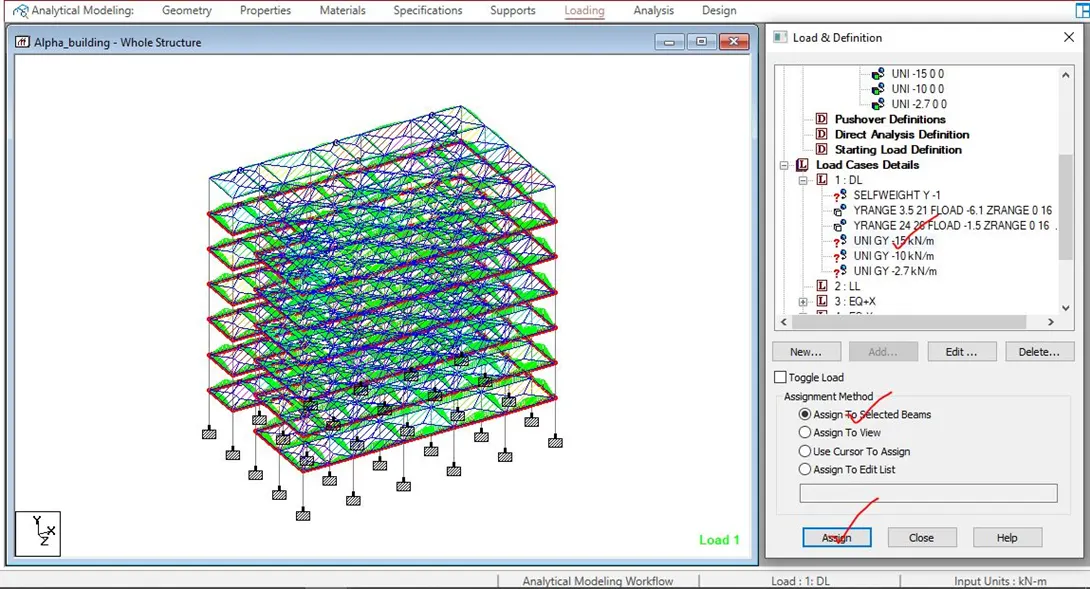
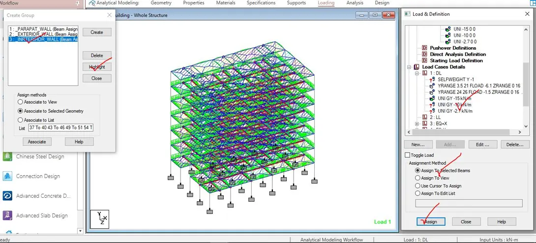
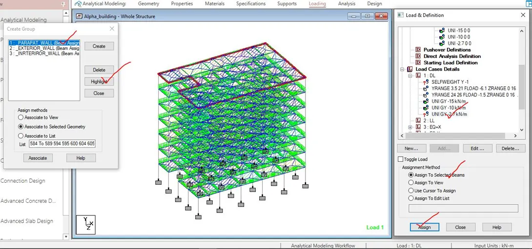
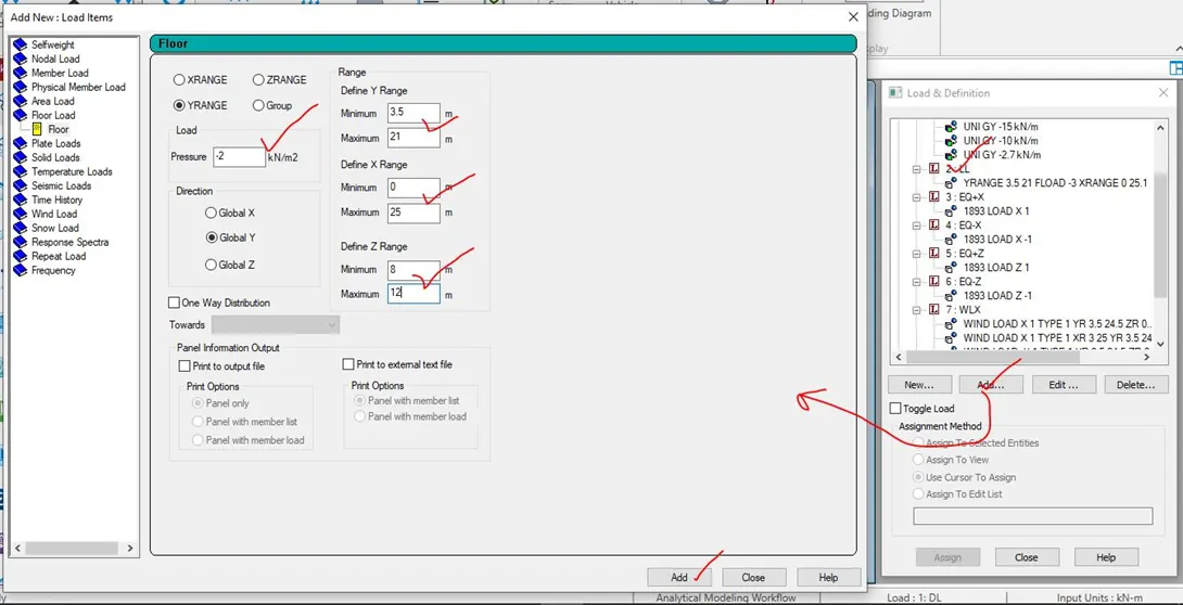
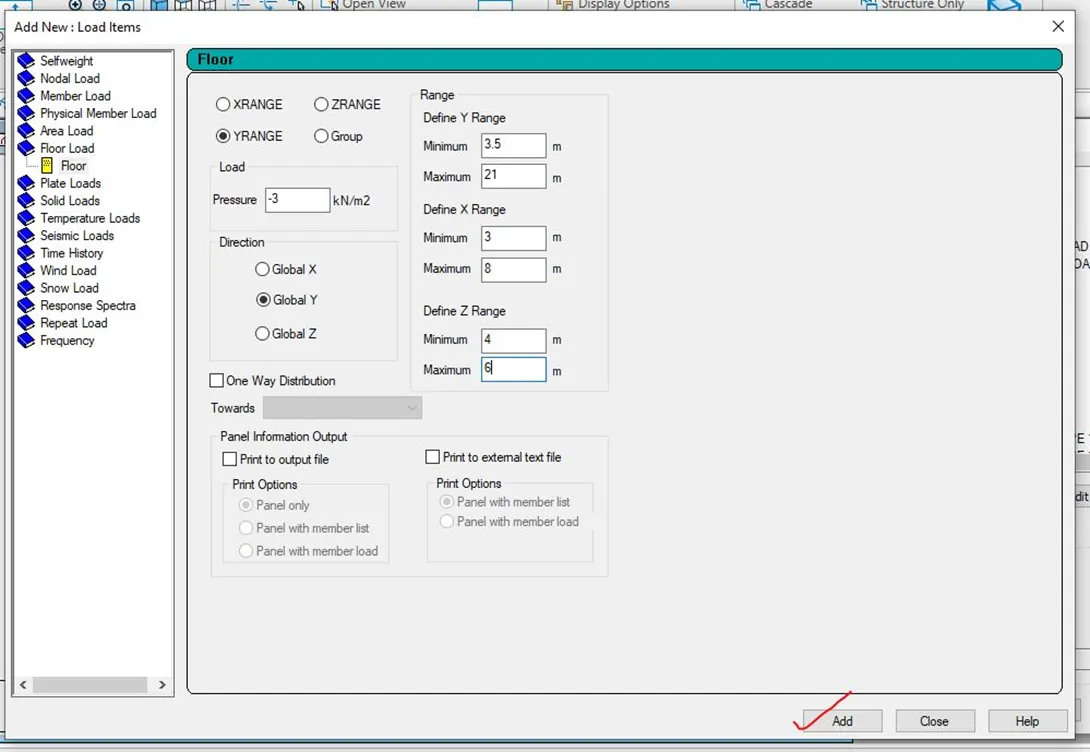
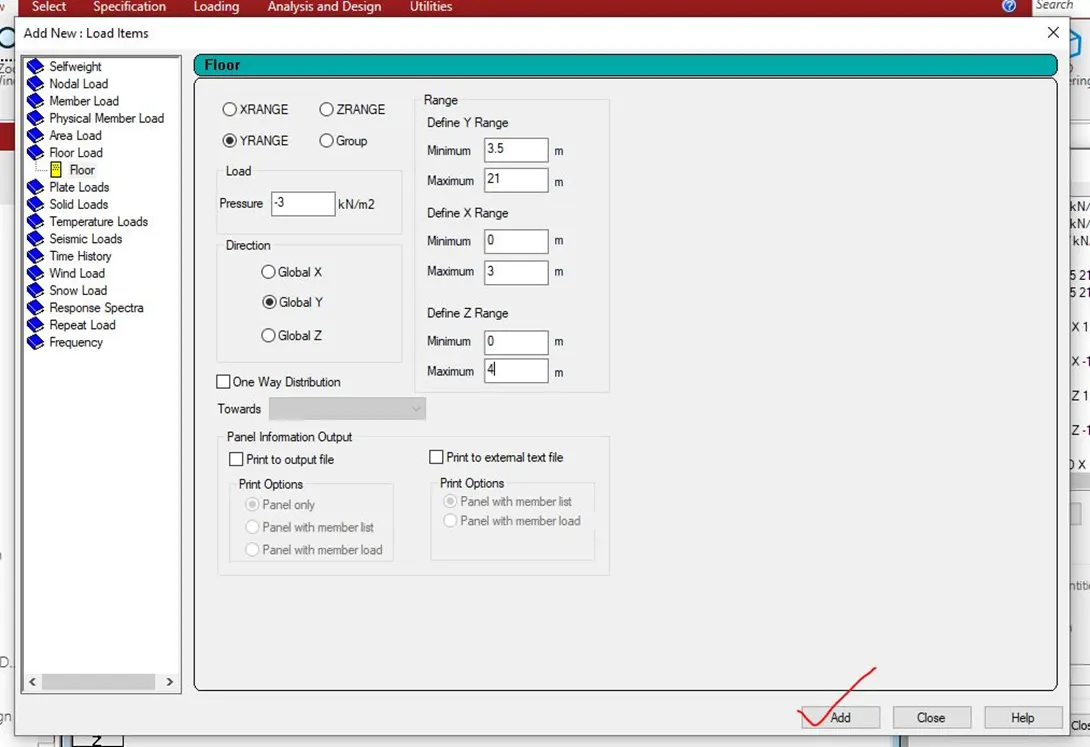
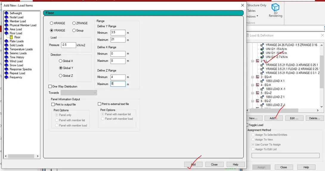
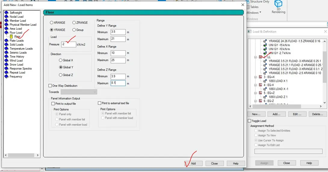
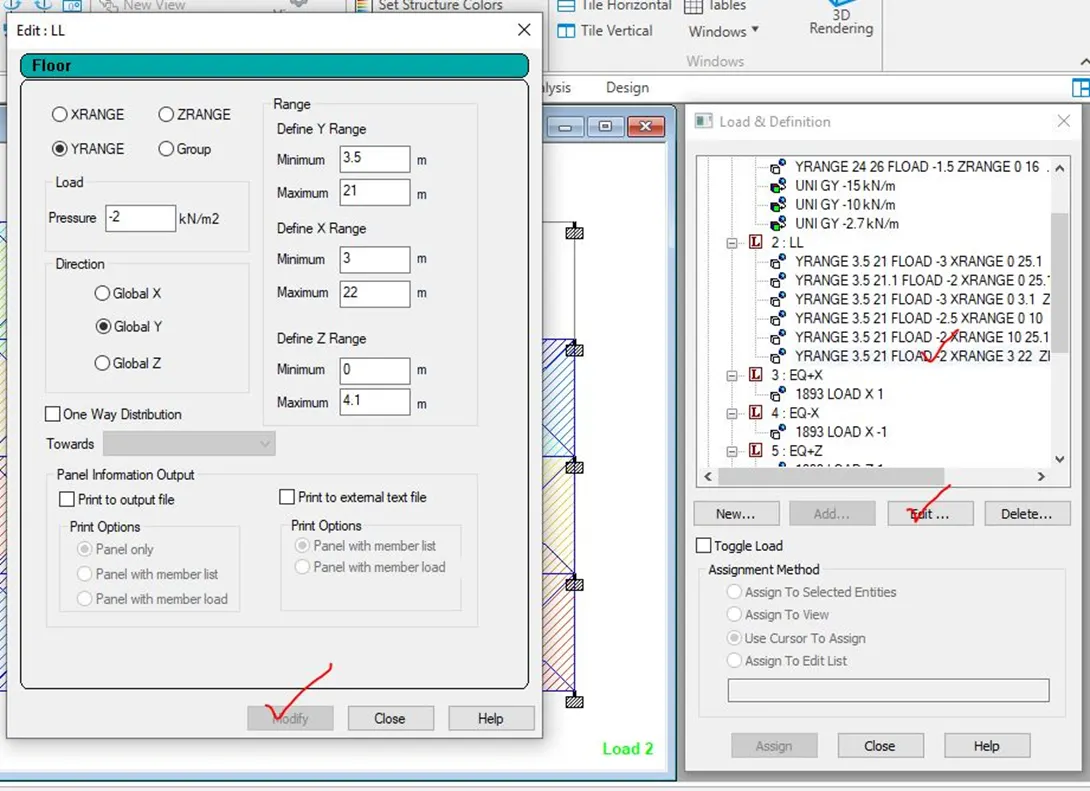
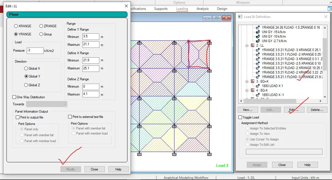
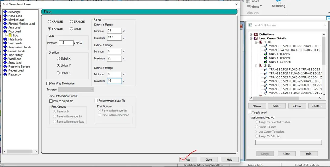
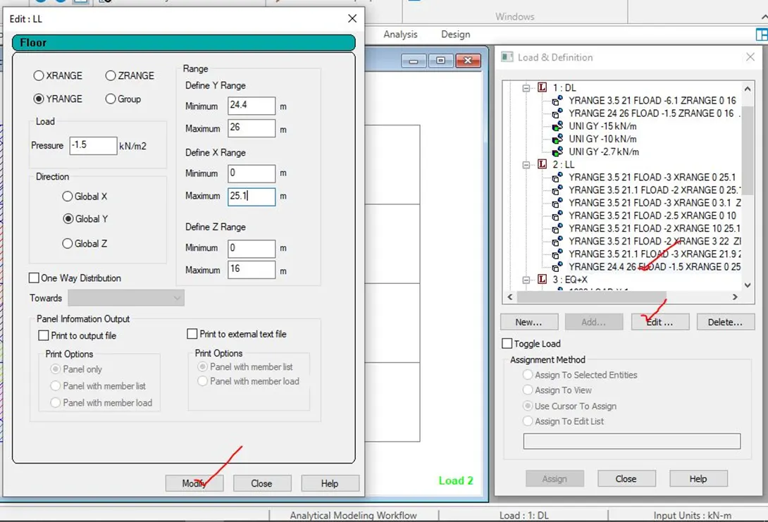
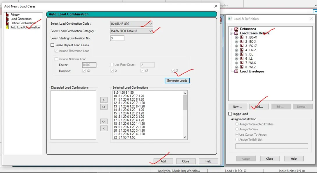
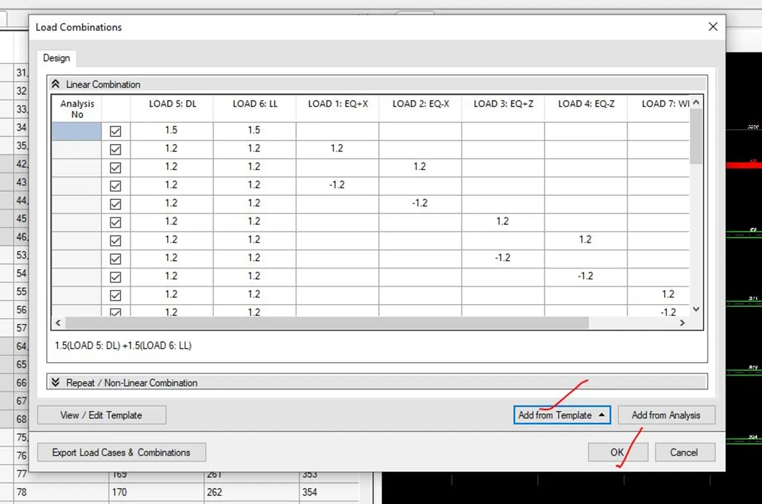
Step-7- In this step, the structure has been analysed and then the designed parameter has been added and load combination as per the IS 456 has been added.
5.2 All the procedural screen shots in Preparing of DL, LL, WL and EQL load calculations as per IS 875 standards

5.3 Results-
The file named as Alpha_building.std releated to the creation, assignment of DL, LL, WL and EQ load to the structural model using STAAD pro has been uploaded.
6. Designing of slab element using MS – Excel
6.1 Procedure in designing the slab element using MS –Excel
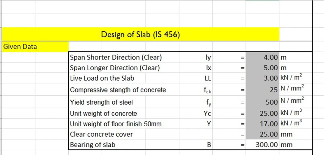
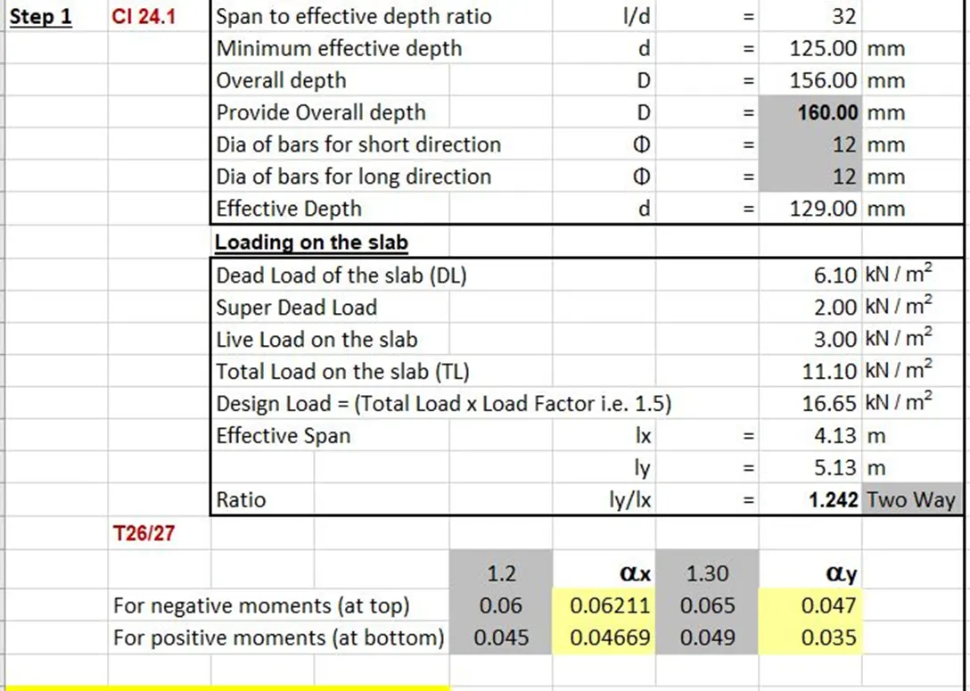
Step1- Calculation of the effective depth, loads on the slab and the moments
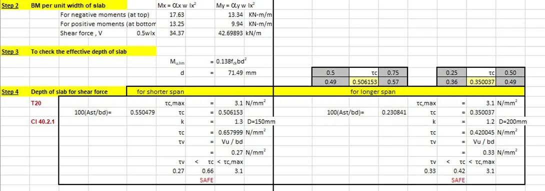
Step2- calculation of BM per unit width of slab
Step3- To check the effective depth of slab
Step4- Calculation of the Depth of slab for shear force
Step5- Determination of areas of steel
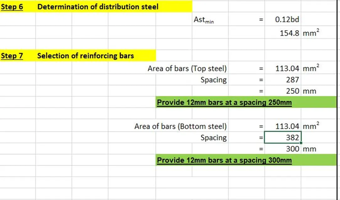
Step6- Determination of distribution steel
Step7- Selection of reinforcing bars
6.2 All the Screenshots of the stepwise Procedure in designing the slab element using MS –Excel has been given below,

6.3 Results-
The file named as project_1_Design of slab.xlsx excel file releated to design of the slab has been uploaded.
7.Designing of beam and column element using STAAD RCDC.
7.1 Procedure in Designing of beam and column element using STAAD RCDC.
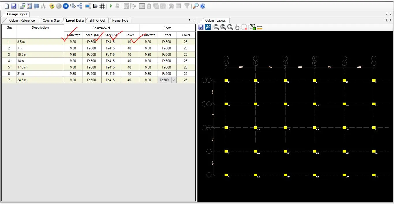
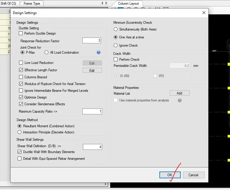
Step-1- After the analysis part complete in the staad pro, the design parameters and load combination as per the IS 456 of the structure has been added to the model and then this model has been proceed to the STAAD RCDC for the design of the column and beams.
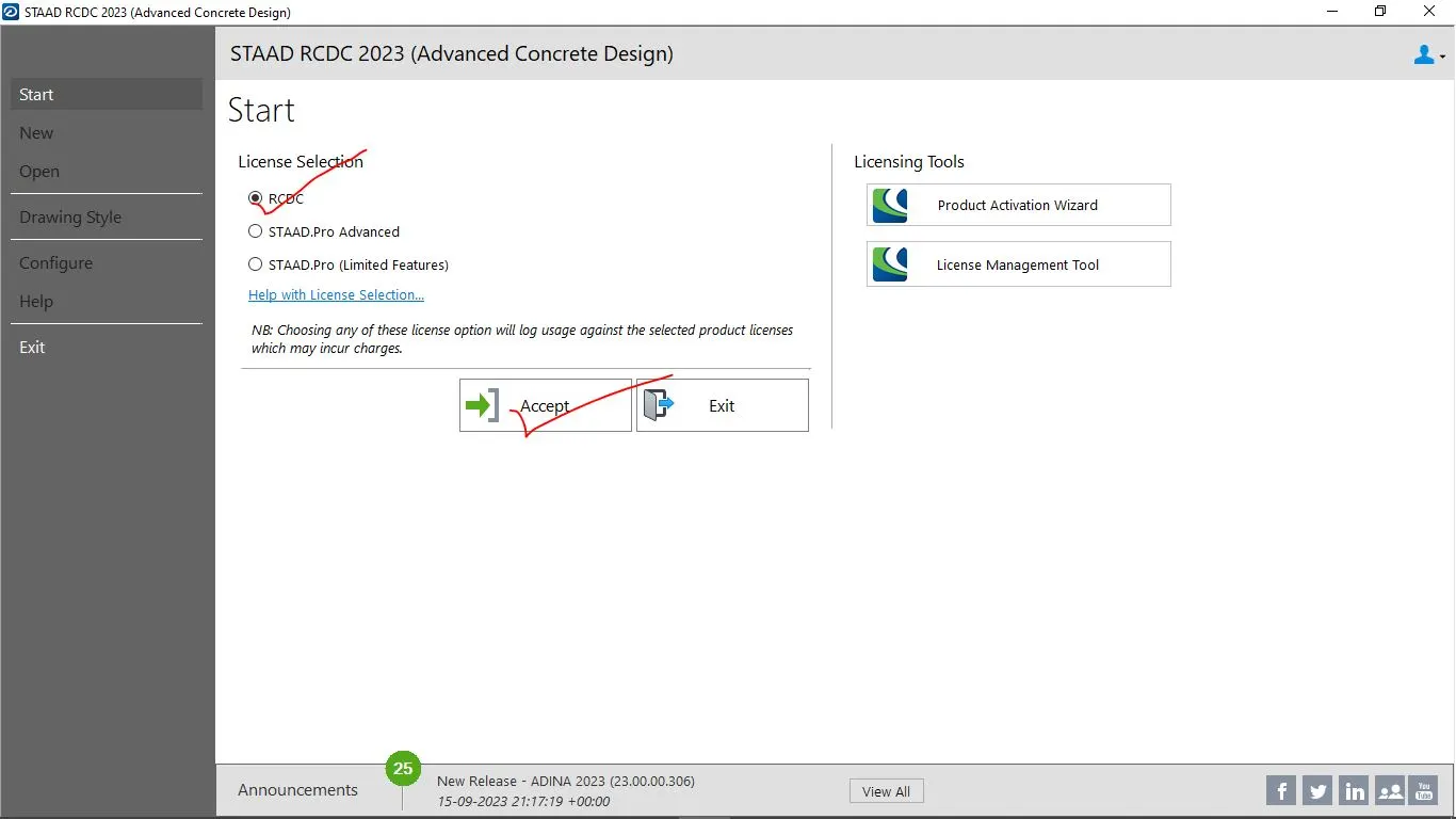
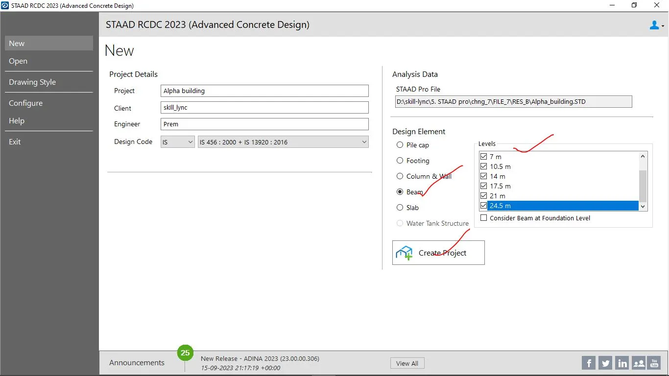
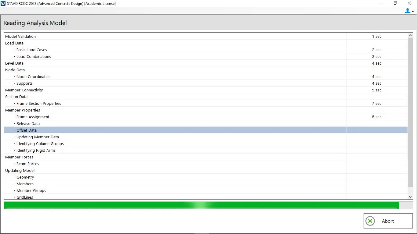
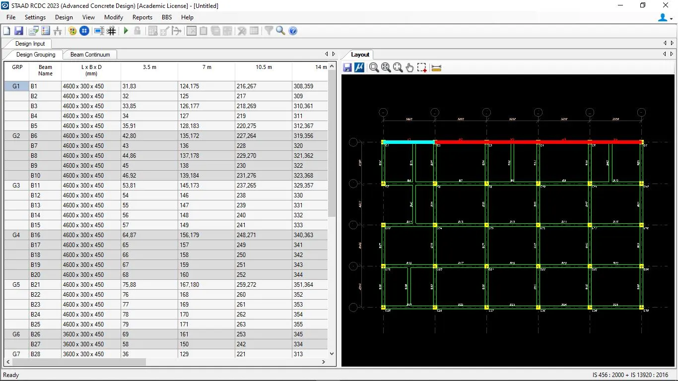
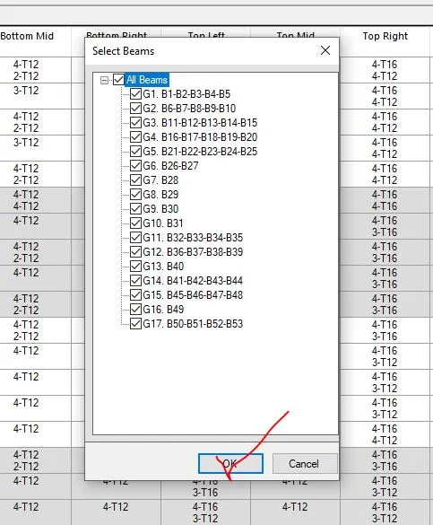
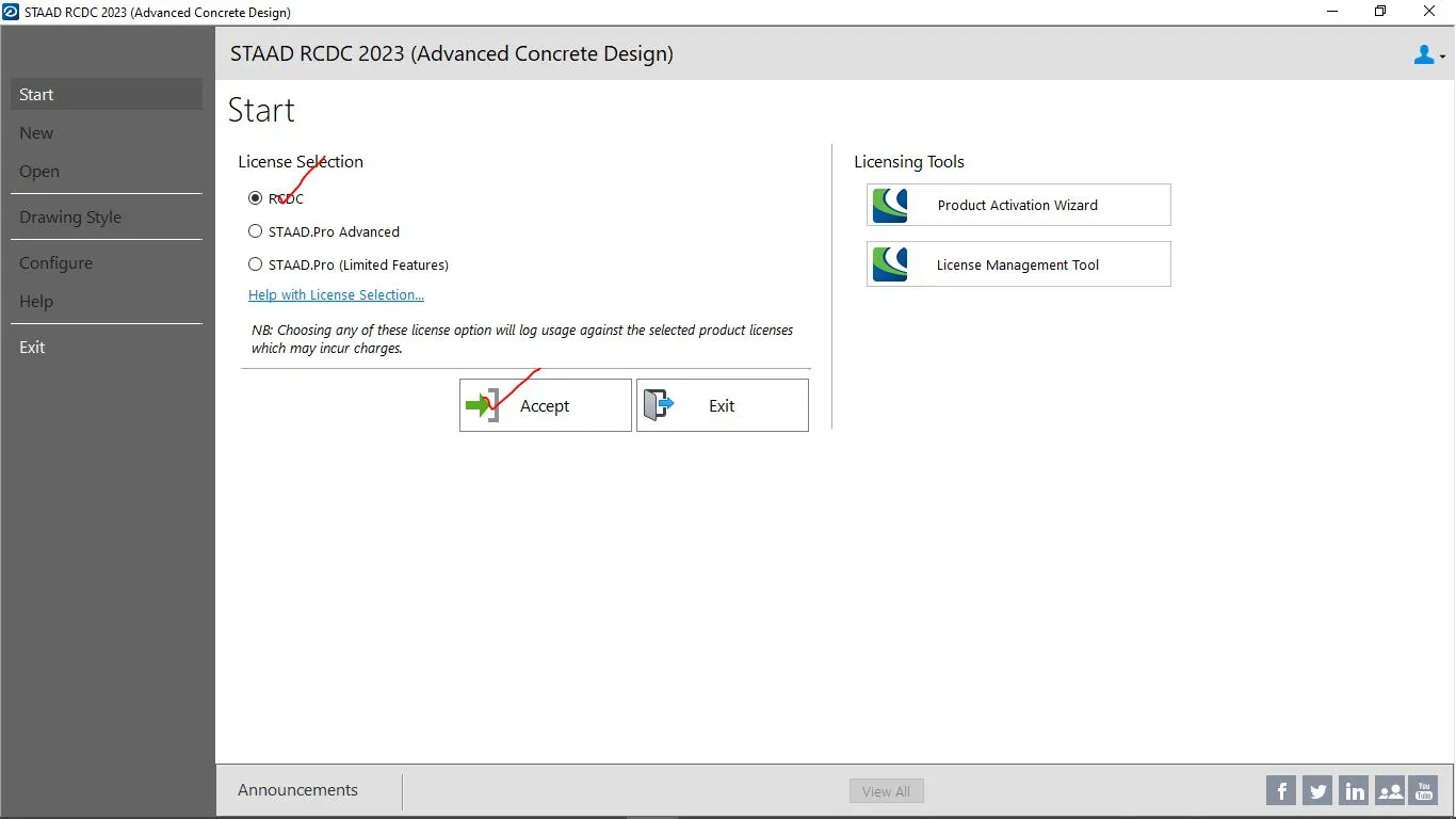
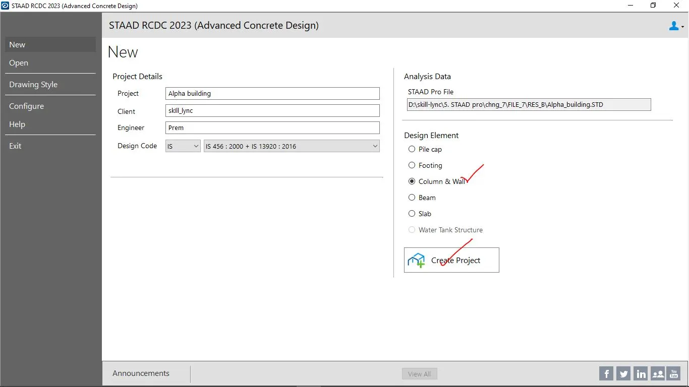
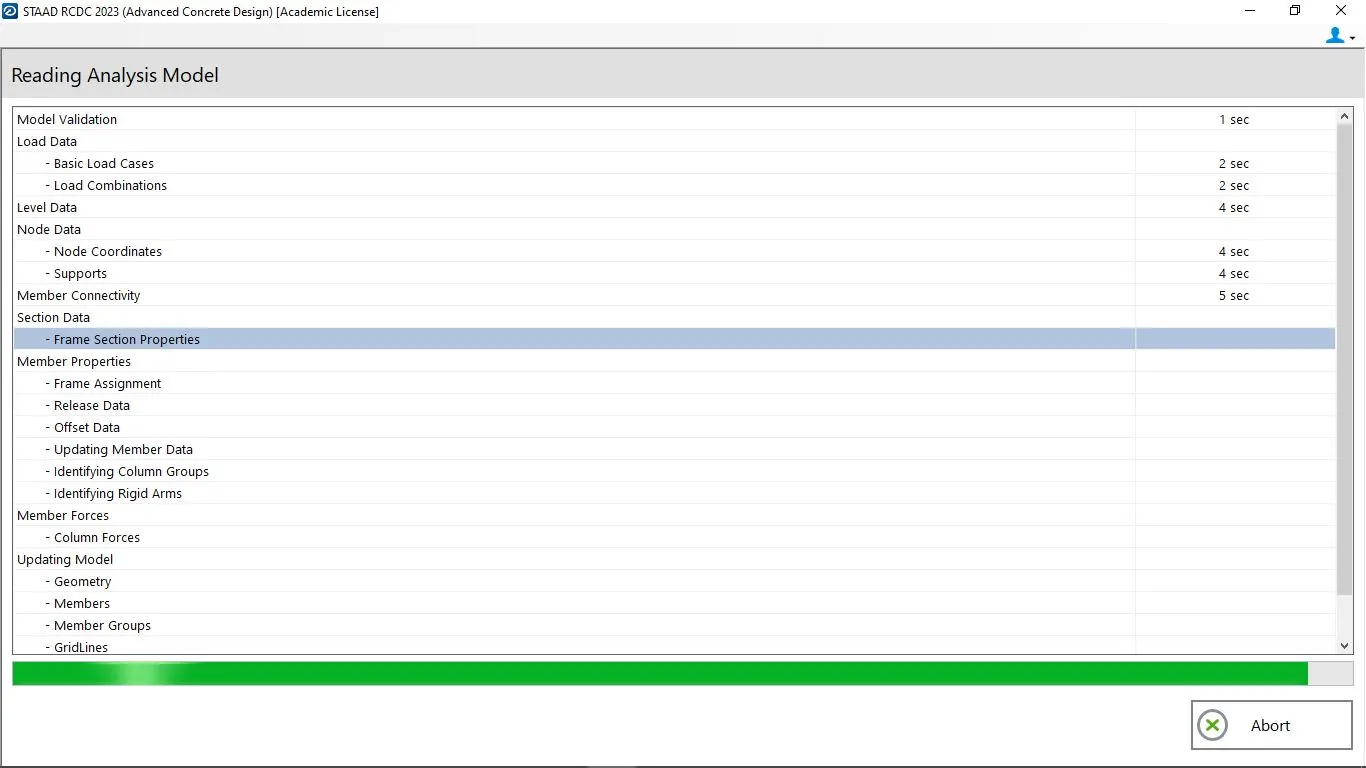
Step-2- To use the Staad RCDC, there is option called advanced concrete design which has been utilised here. After clicking the advanced concrete design, a new window will open where we have to give specified the license section and then the project details and the staad file has been uploaded with the design element for beam and column as per design which is to be designed and levels has also been selected.
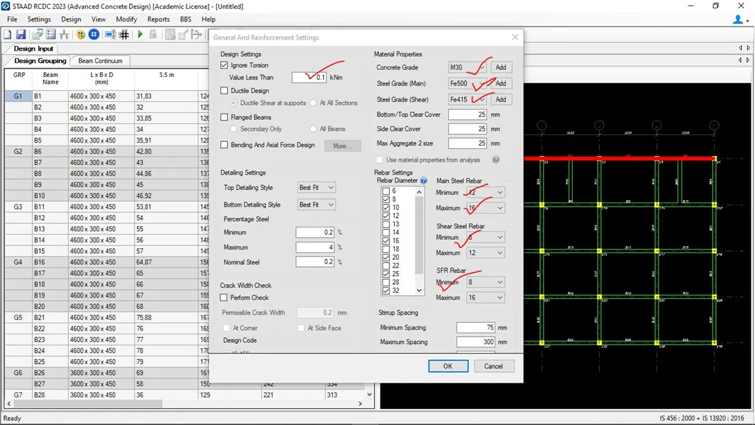
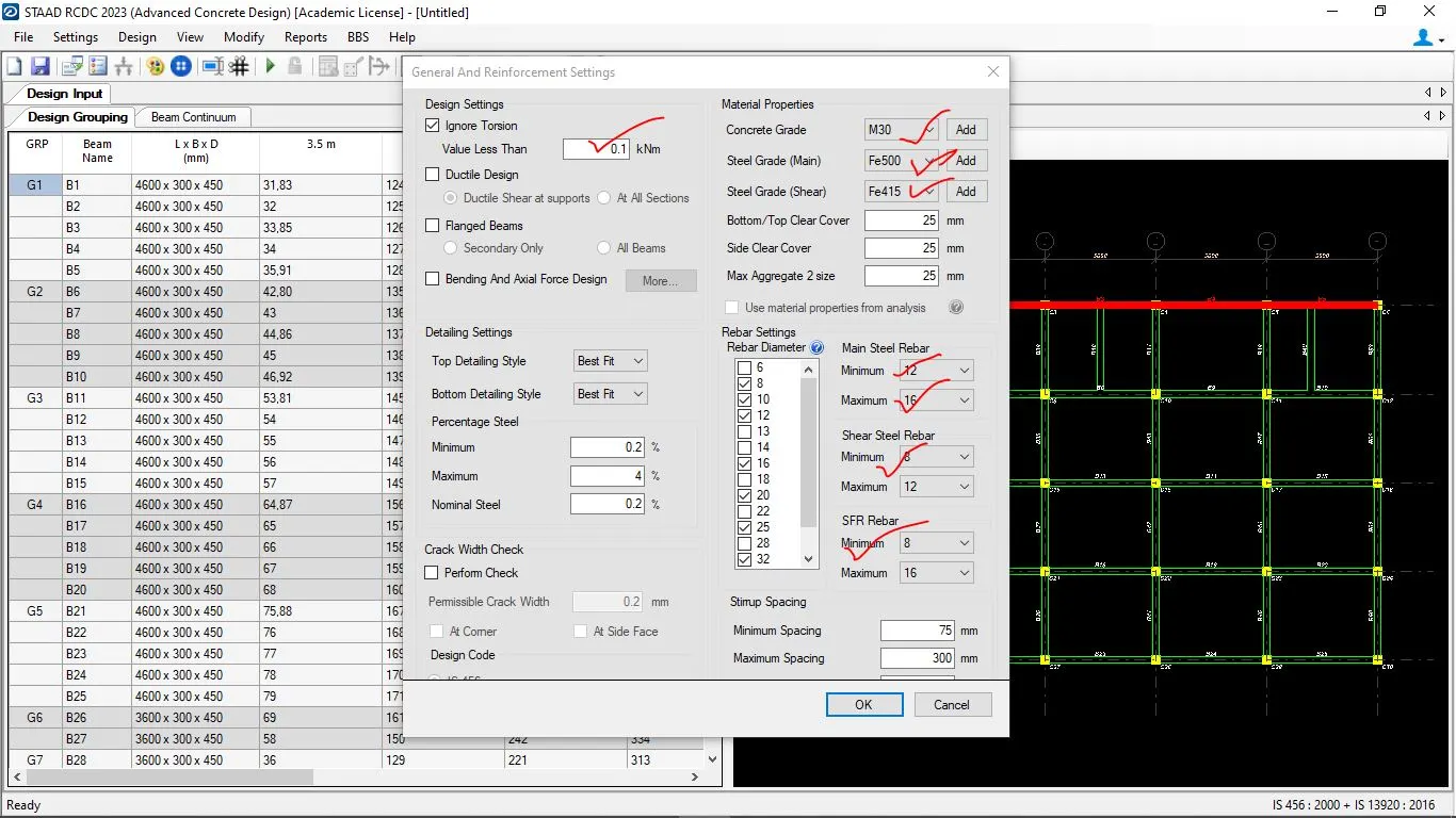
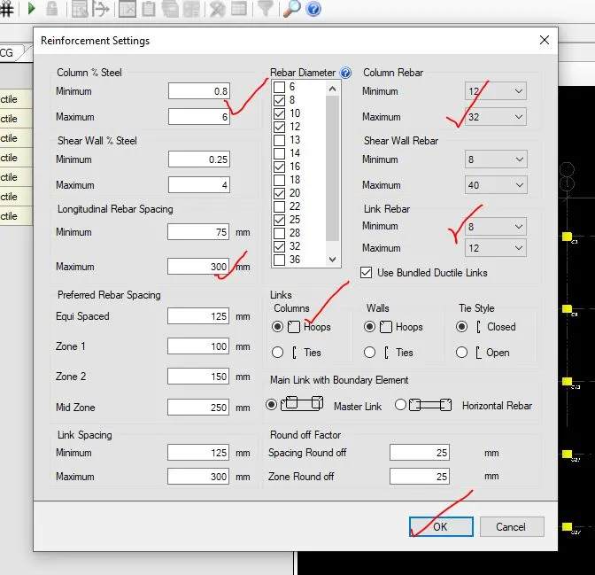
Step-3- Then the general and reinforcement details has been added which has been shown below,
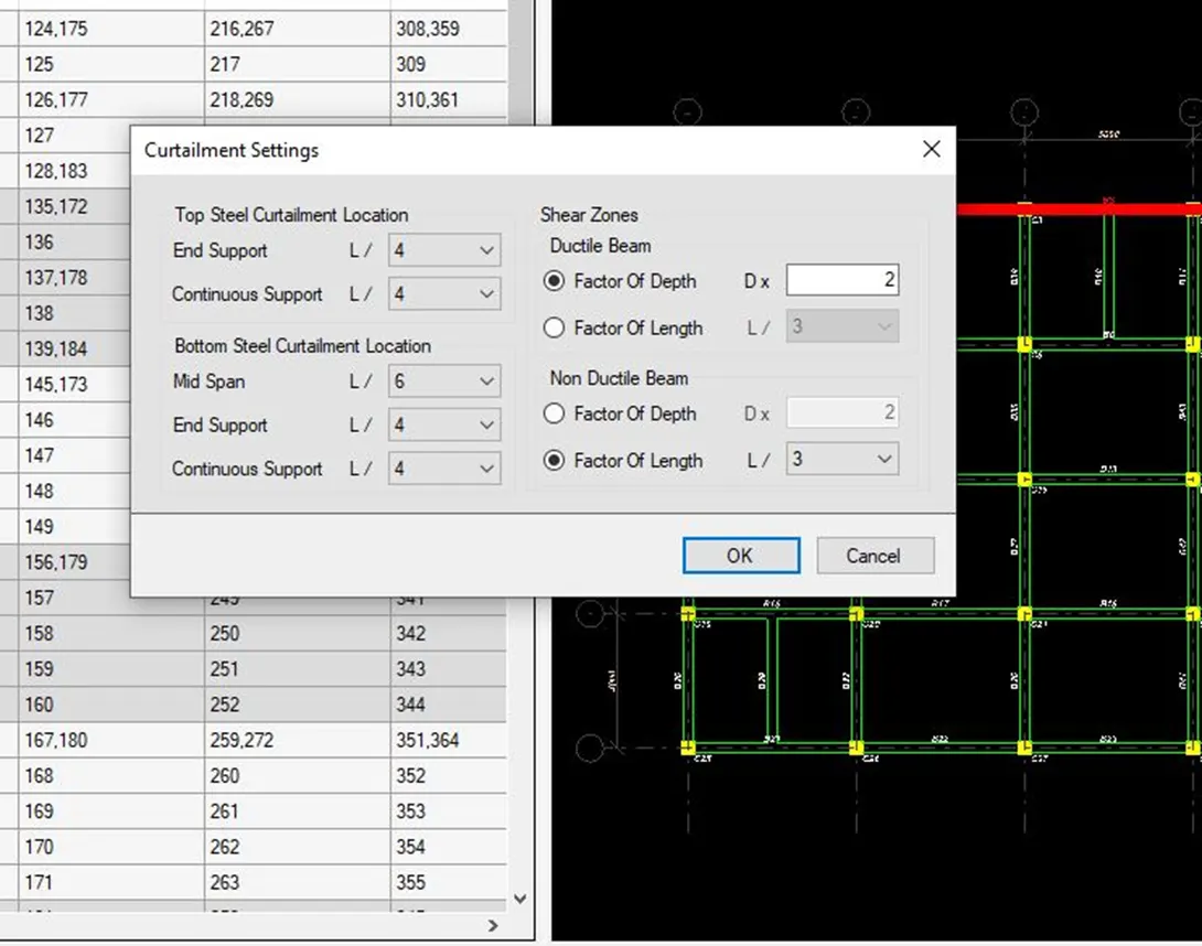
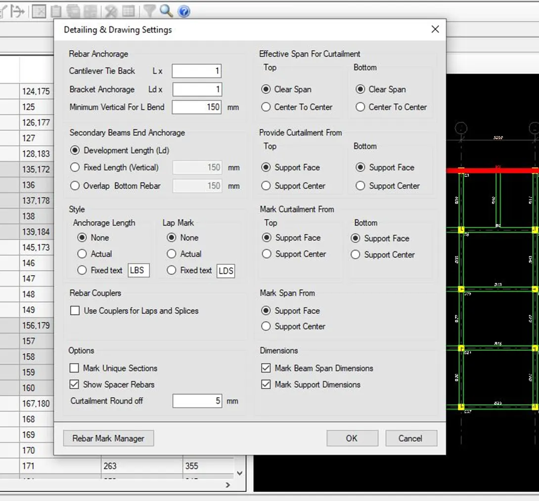
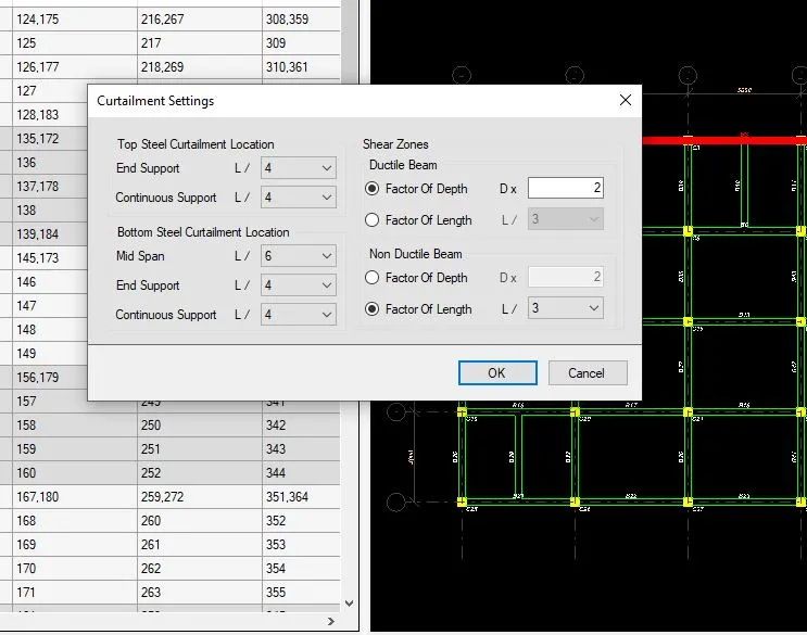
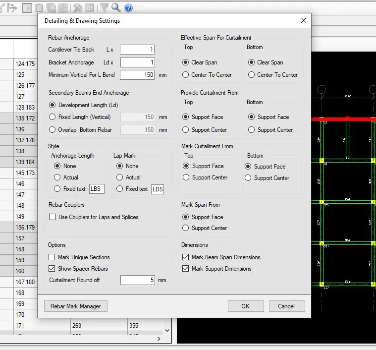
Step-4- Then curtailment setting and detailing and drawing setting has been provided as per the Is requirement which has been given below,
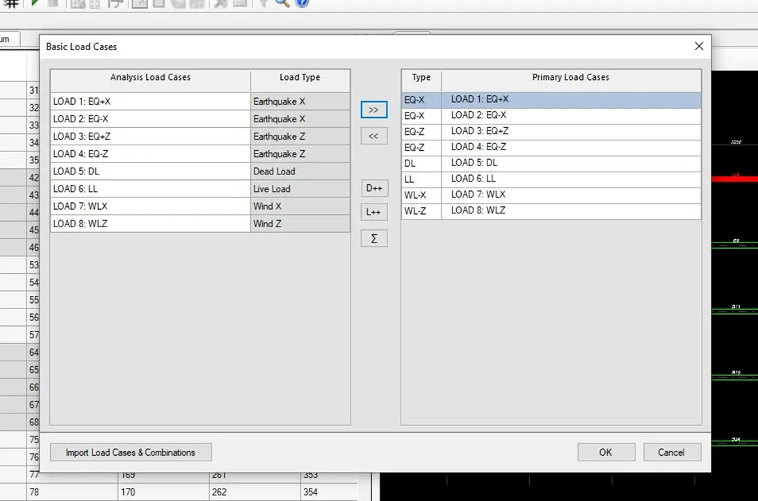
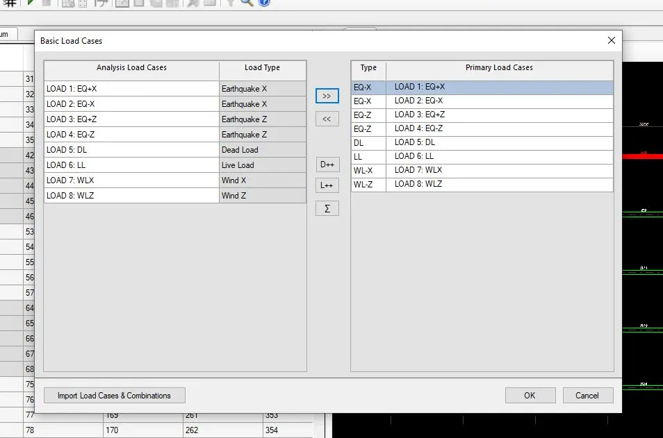
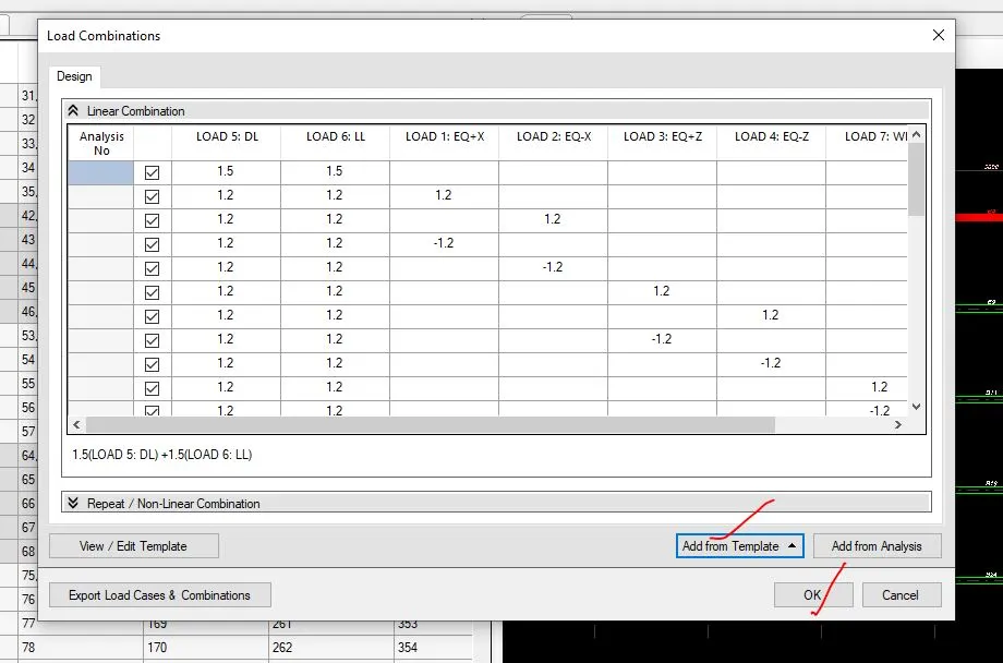
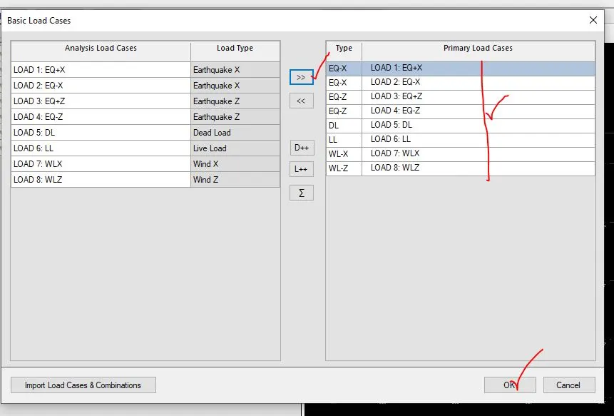
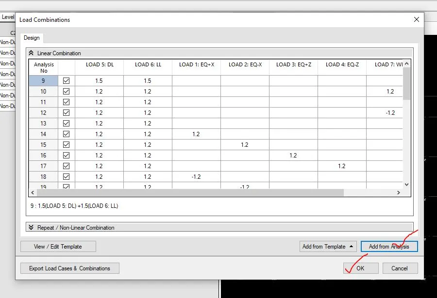
Step-5- then the basic load cases and load combination has been added which has been shown below,
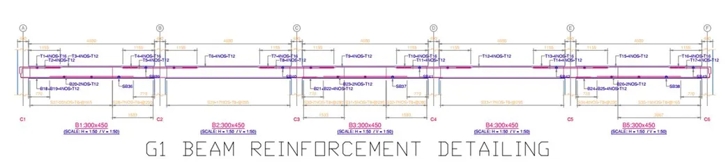
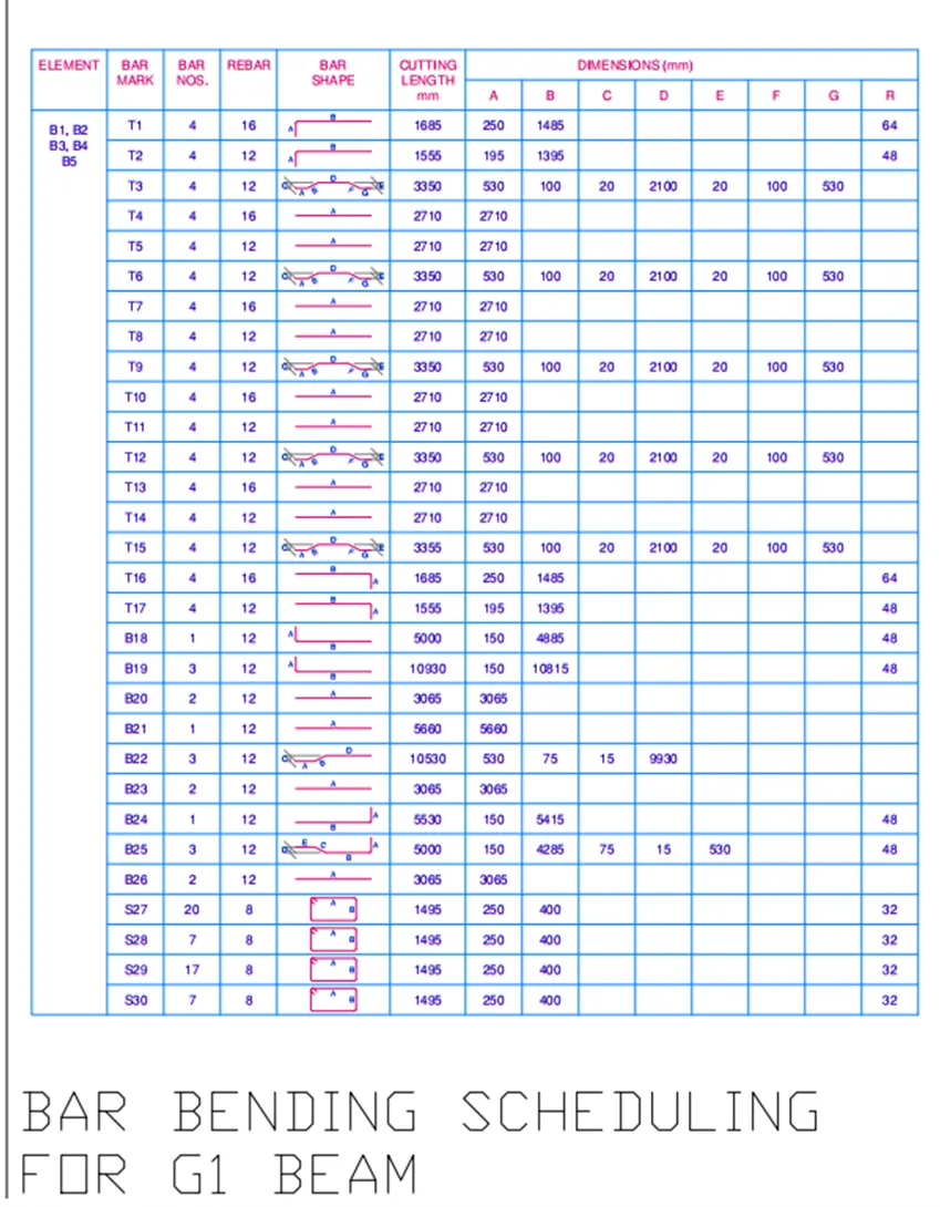
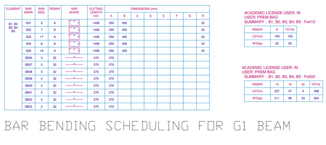
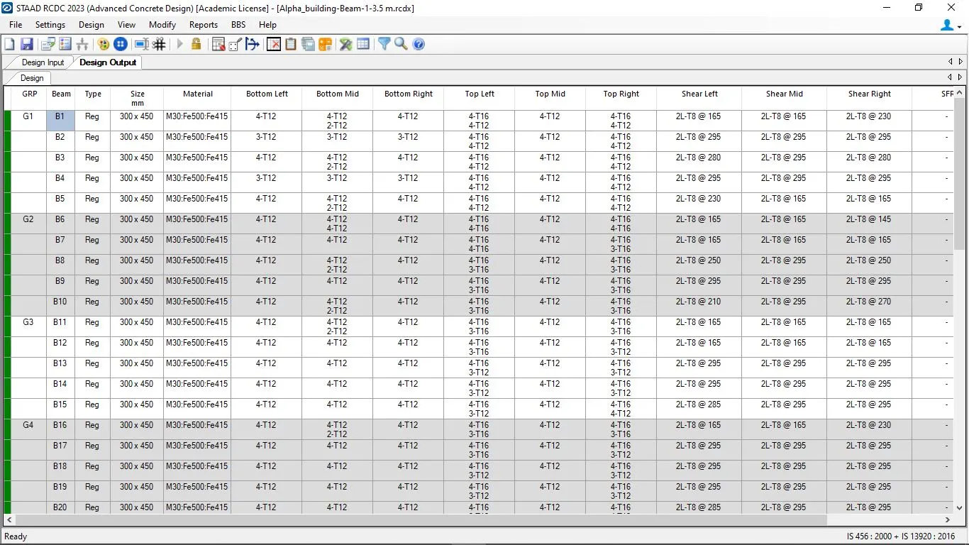
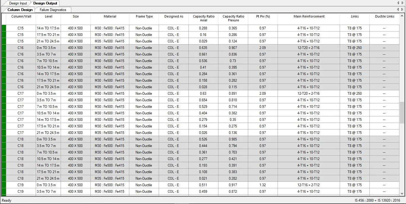
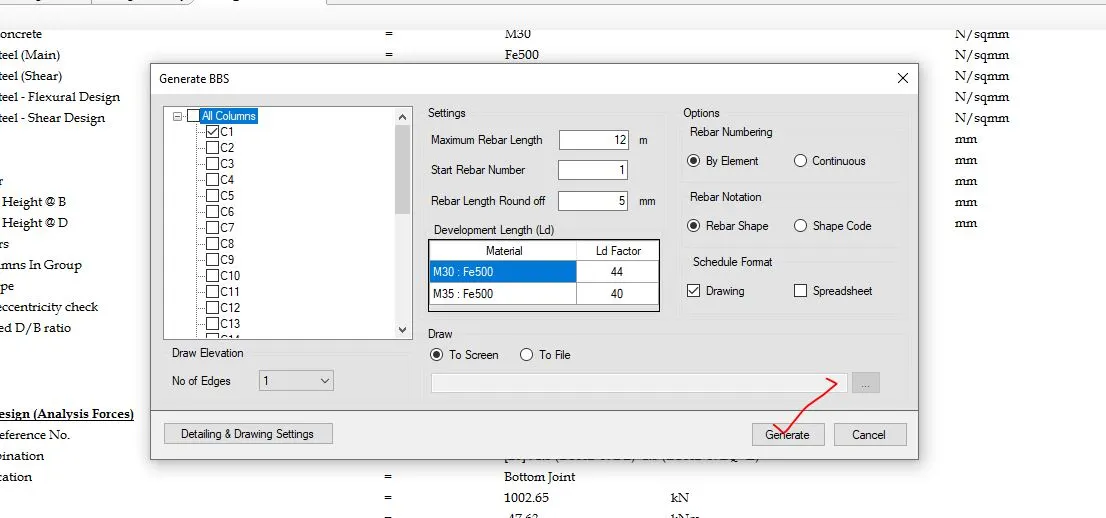
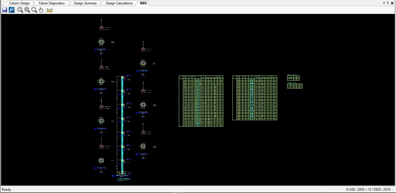
Step-6- After assigning of the design details and the design has been done. After the successfully completion of the design the BBS, design summery and design calculation has been produced by using RCDC.
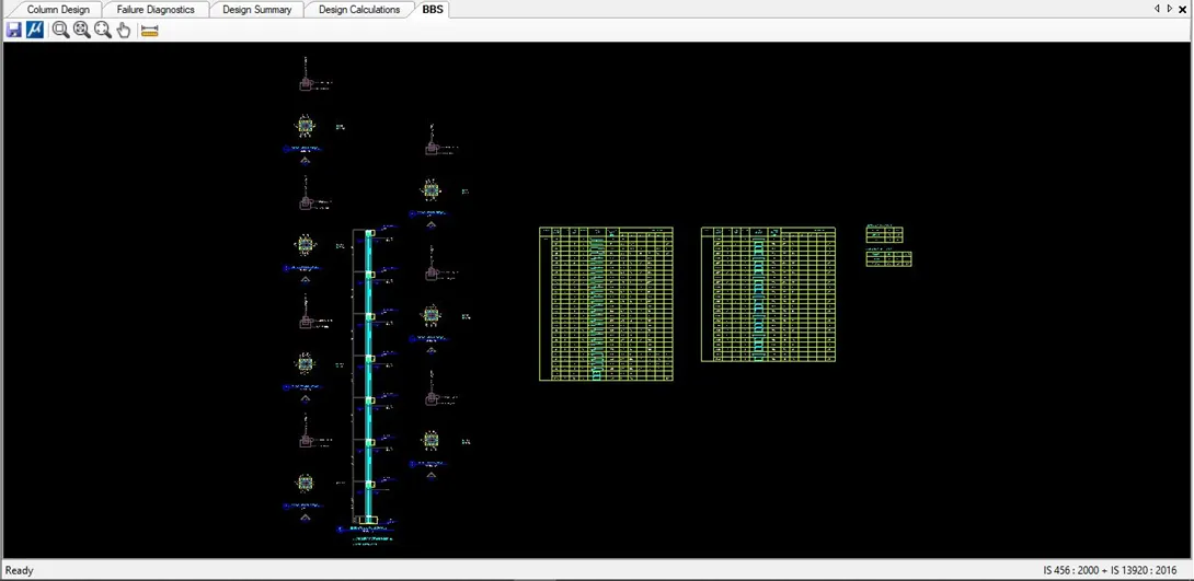
Step-7- For the design of the column same procedure has been adopted and design summery, column calculation and BBS of the column has been issued by using Staad RCDC.
7.2 All the procedural screen shots in designing of the column and beams by using STAAD RCDC

8. Designing of Foundations using STAAD Foundation.
8.1 Procedure in designing the foundation using staad foundation
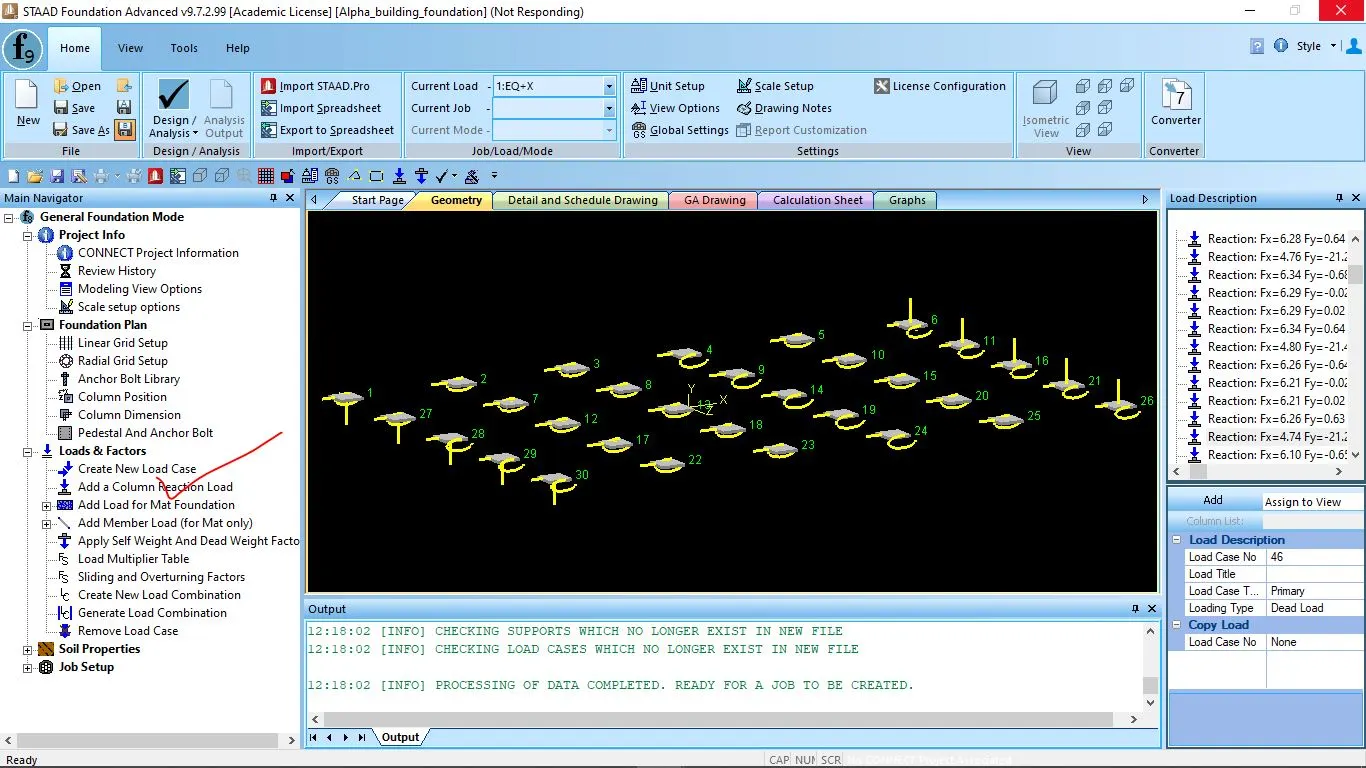
Step1- Firstly the staad pro file of the building project has been opened in the staad pro software. Then the in workflow the foundation design has clicked and then for the foundation design support condition and load condition has been chosen and the STAAD foundation advance has been opened.
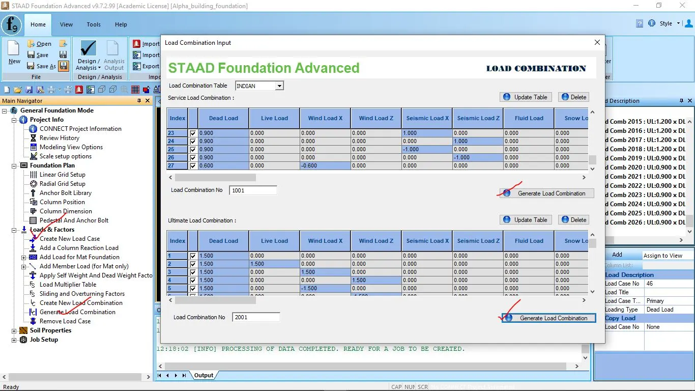
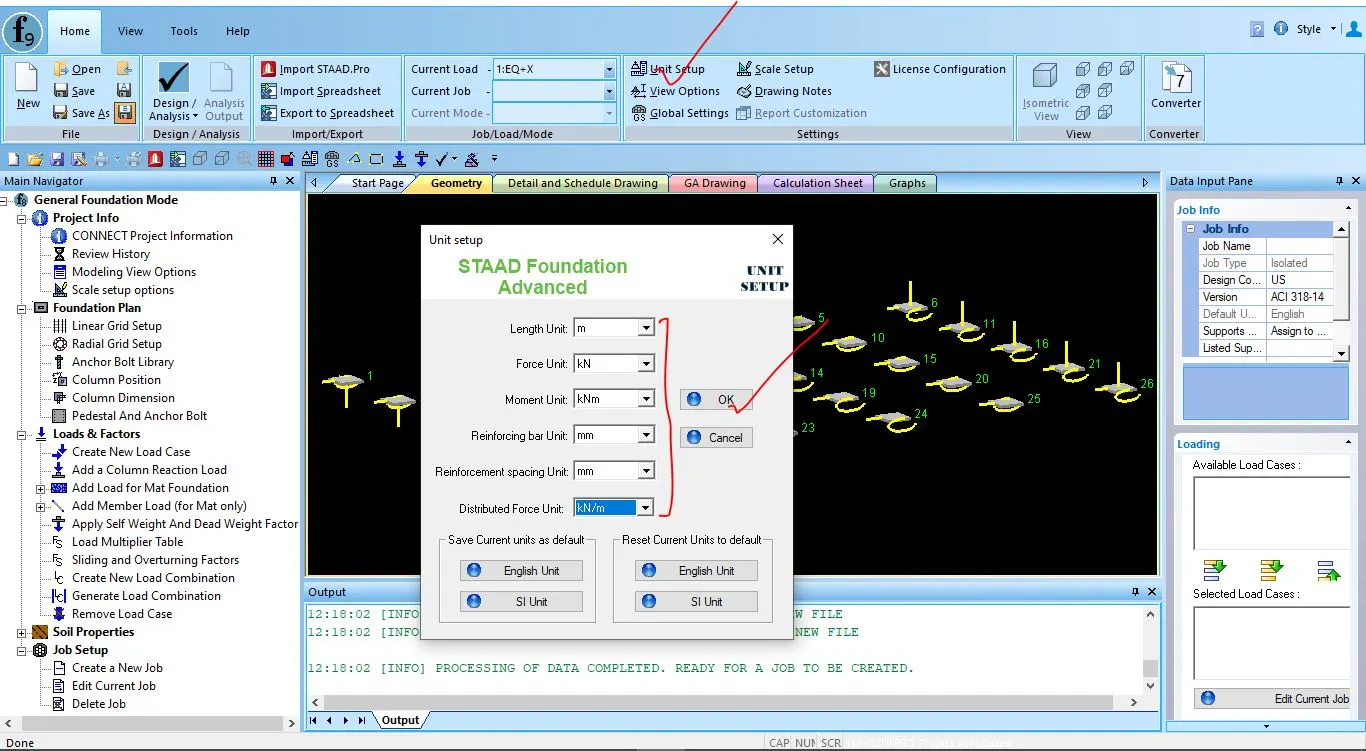
Step2- Then load combination for the service load and ultimate load has been generated as per the IS codes. And then the unit for the structure has been checked.
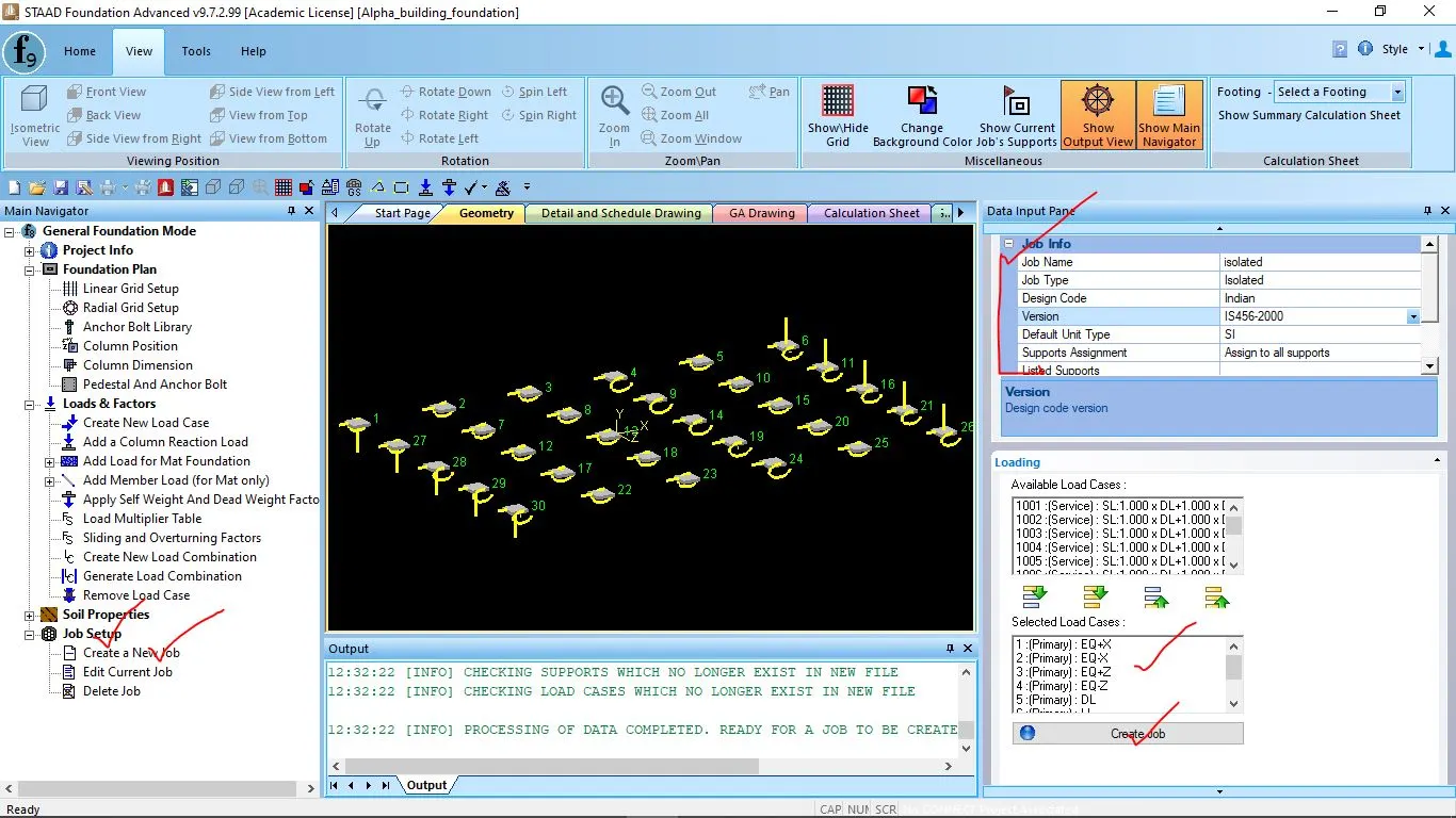
Step3- in this step the job setup has been created where the job name, job type, design code, unit and load condition has been added and a job has been setup.
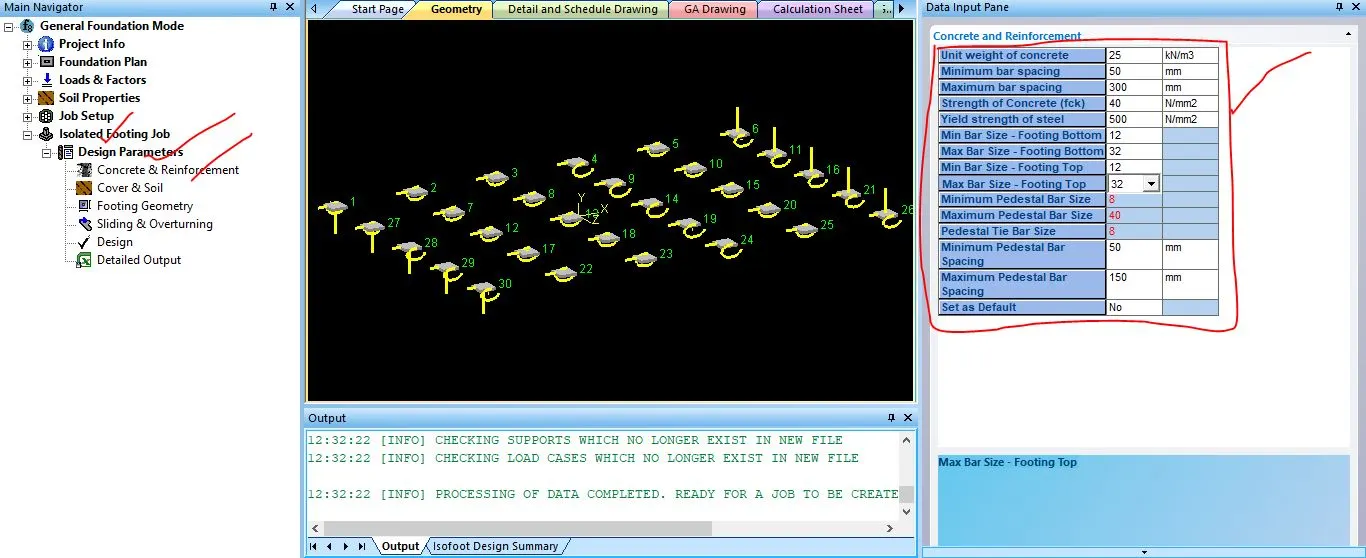
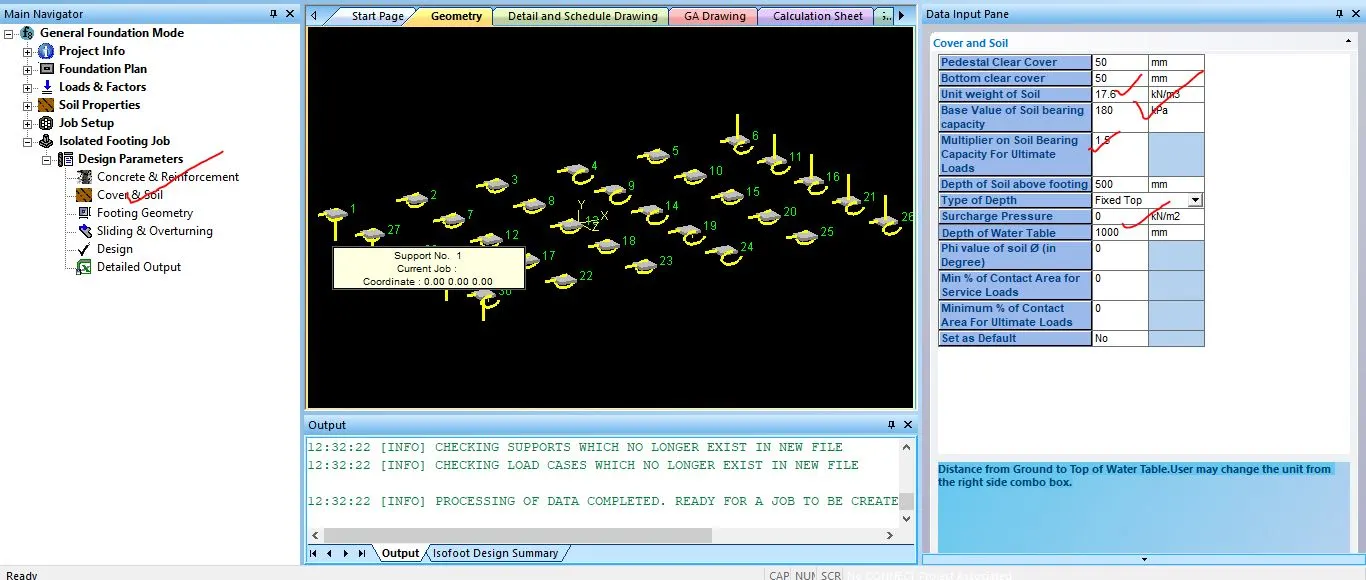
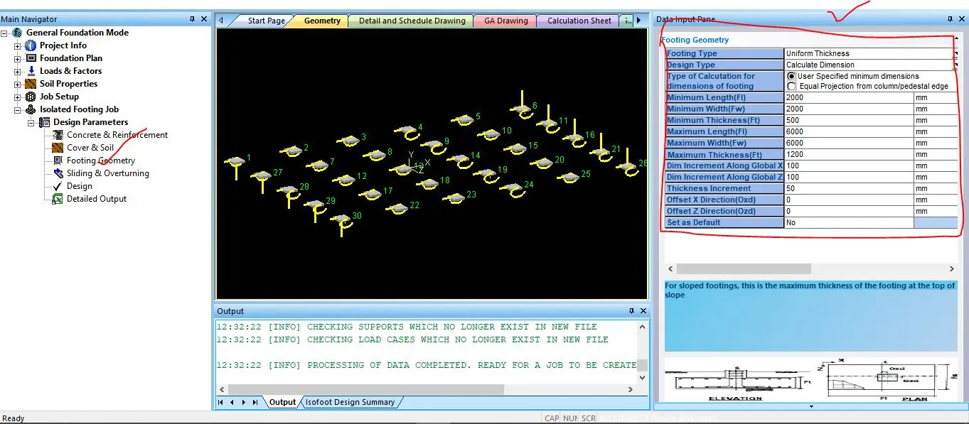
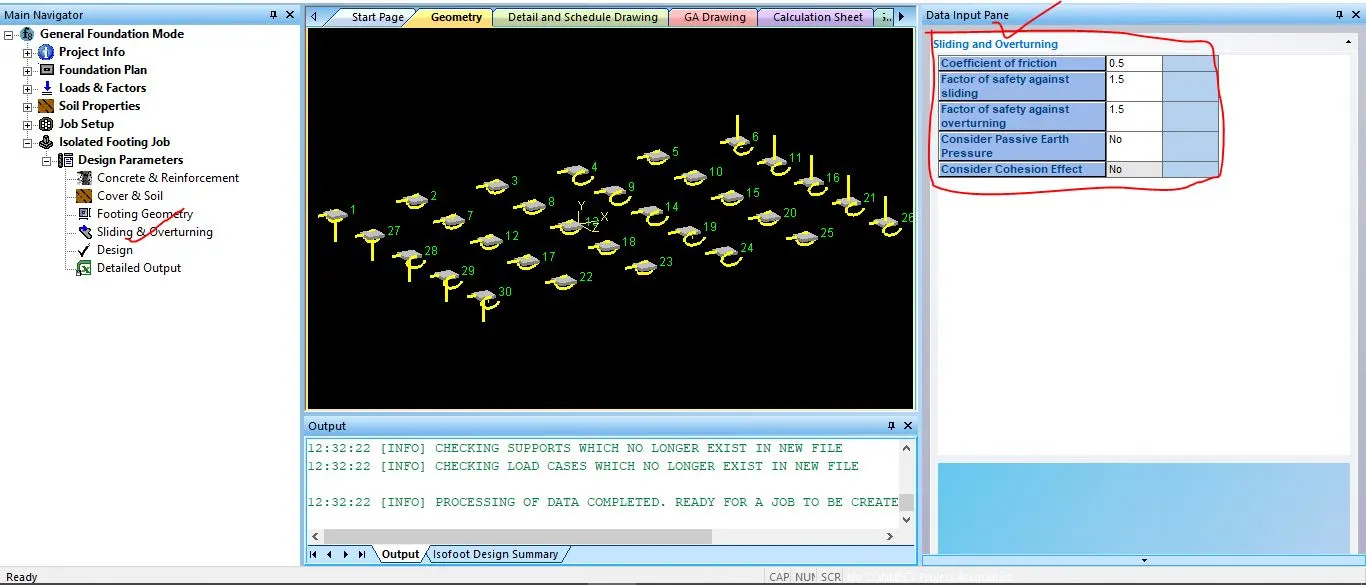
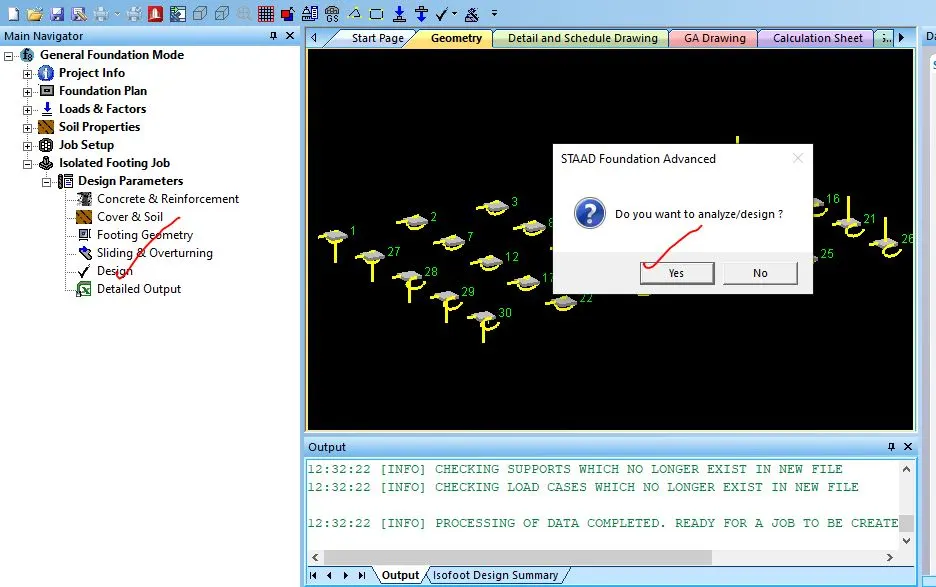
Step4- Then the design parameter for the foundation here in this project the isolated footing has been used i.e. concrete and reinforcement, cover and soil, footing geometry, sliding and overturning design data has been added according the requirement.
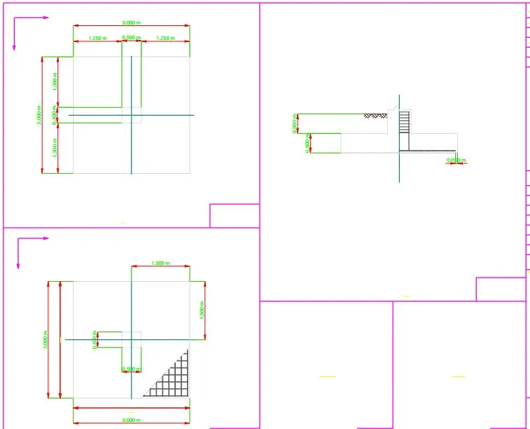
Step5- In this step the design has been performed and checked. The detail and schedule drawing, foundation calculation sheet has been created using STAAD foundation which has been shown below,
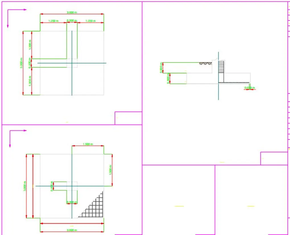
All the procedural screen shots in designing the foundation using STAAD foundation
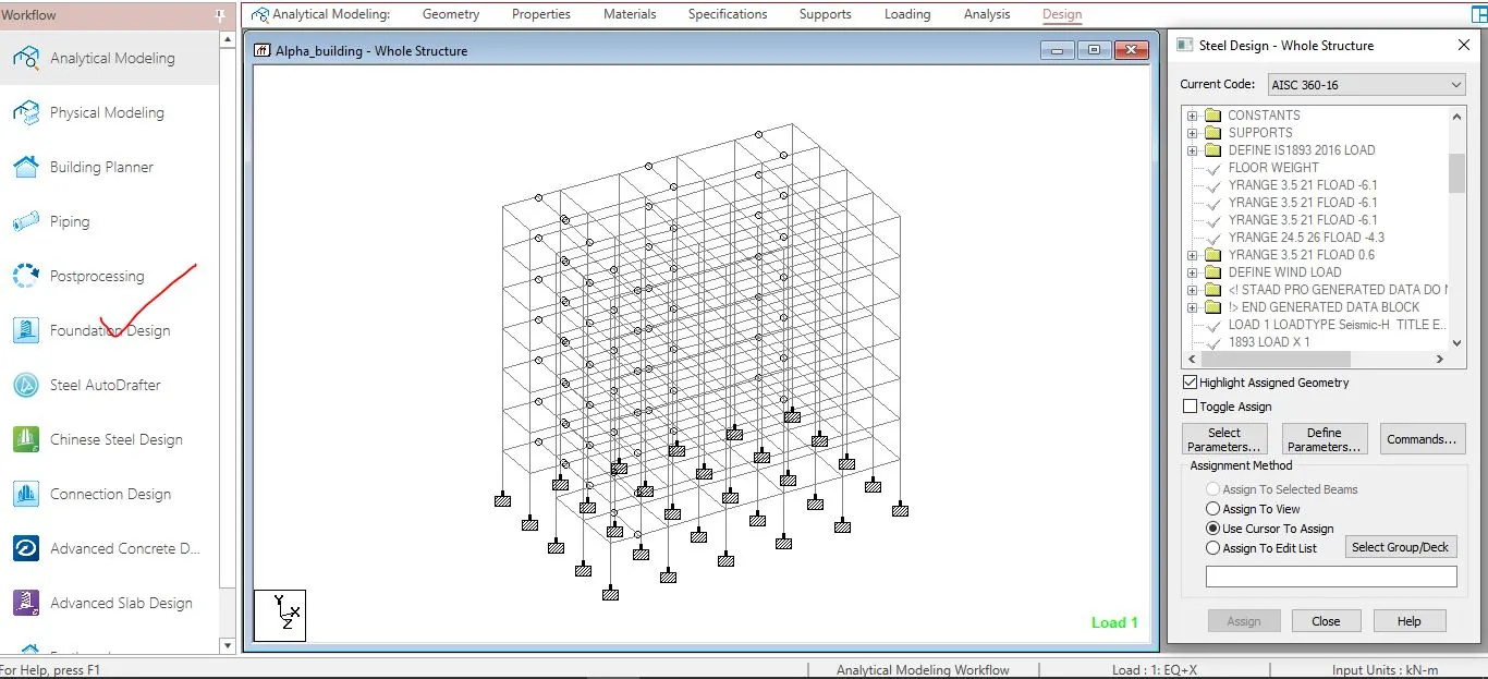
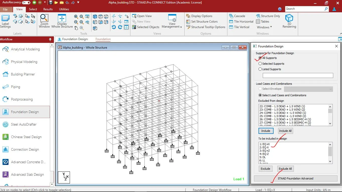
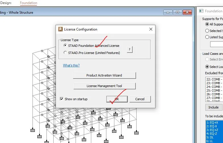
8.2 Result-
The file named as Alpha_building_foundation.sfa related to the designing of the foundation using STAAD foundation which has been uploaded.
9.The necessary file name related to the project which has been uploaded.
1. Alpha_building.std
2. RES_B.dwg
3. project_1_Design of slab.xlsx
4. DBR of Residential building_alpha_bangalore_project-1.pdf
5. Alpha_building.sfa
5. bbs_column_C1_alpha_building.dwg
6. bbs_G1_alpha_building.dwg
7. detail_drawing_column_C1_alpha_building.dwg
8. detail_drawing_elevation_column_C1_alpha_building11.dwg
9. bbs_G1_alpha_building-G1 beam.pdf
10. bbs1_column_C1_alpha_building-.pdf
11. bbs2_column_C1_alpha_building.pdf
12. beam design summary.pdf
13. column design calculation.pdf
14. column design summary.pdf
15. design calculation.pdf
16. detail_drawing_column_C1_alpha_building.pdf
17. foundation_calculation-sheet.pdf
18. foundation_detailing.pdf
19. foundation_scheduling_drawing.pdf
20. BEAM LAYOUT.pdf
21. COLUMN LAYOUT.pdf
22. plan.pdf
23. foundation_detailing.pdf
24. foundation_scheduling_drawing.pdf
25. foundation-Layout.pdf