Structural Modelling using Etabs 2018
1.1 Aim of project- To model an apartment with all seismic consideration, based on given architectural inputs and to know how to check the seismic performance of an apartment using ETABS as per IS 456, IS 875 and IS 1893.
1.2 Introduction-
The architectural drawings for G+7 residential building of zone 5 has been given below,
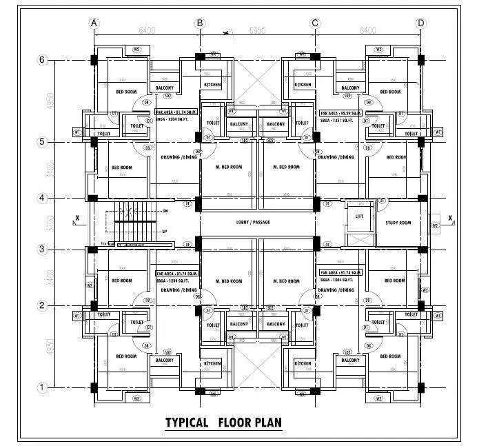
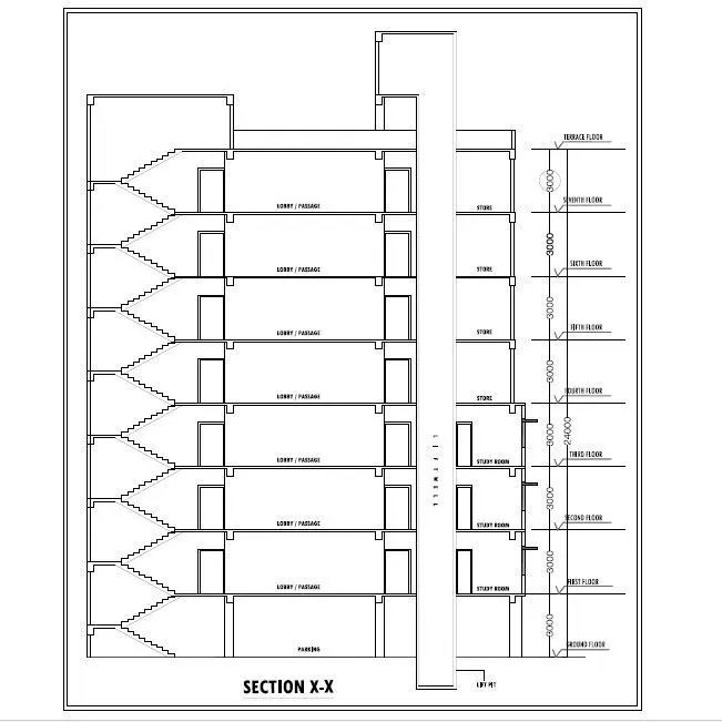
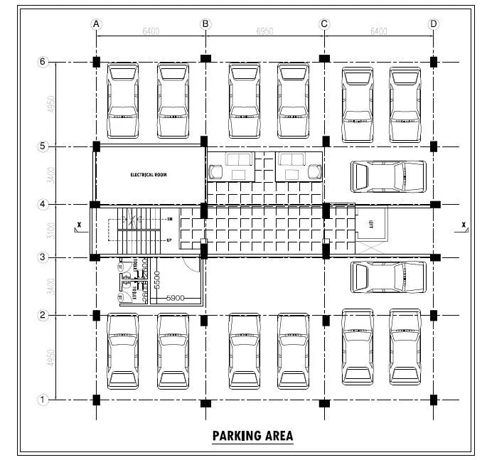
1.2.1 Data required for ETABS analysis,
- Pinned support, Base+ 9 storey (ground to terrace)+ mumty.
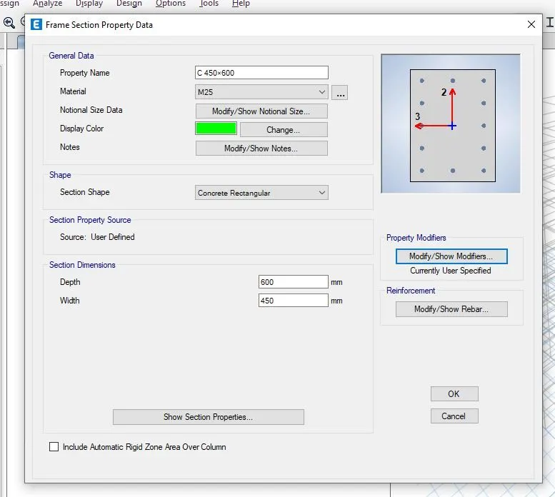
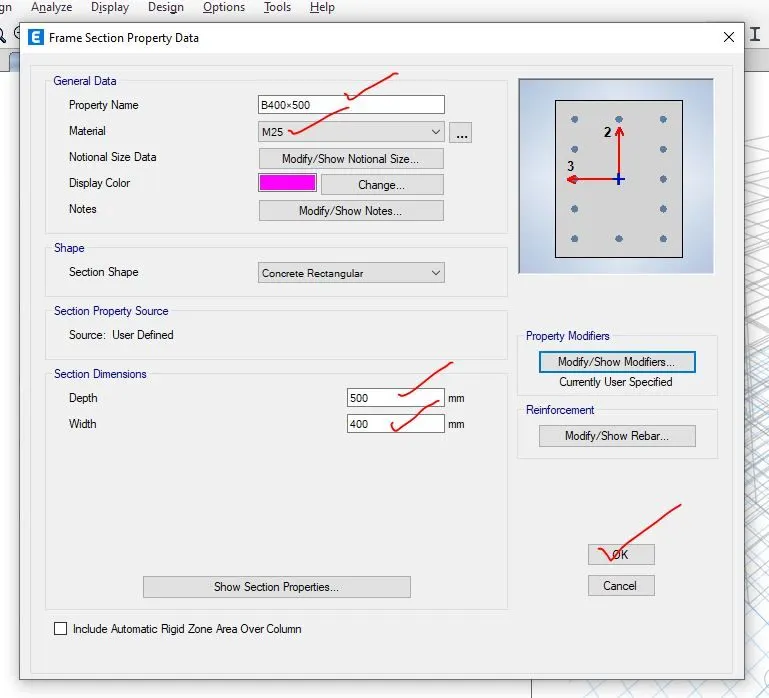
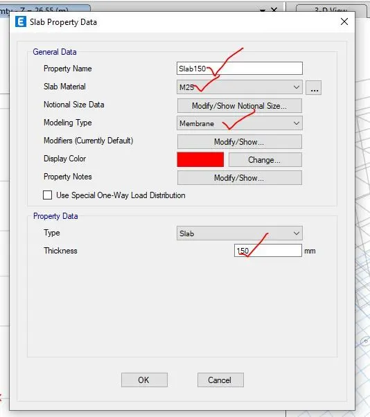
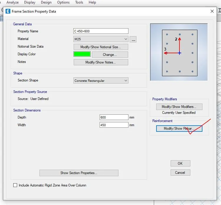
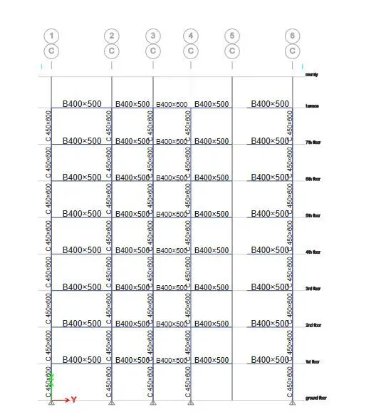
- Column size is assumed as 450mm×600mm, beam size i.e. 400mm×500mm slab of thickness 150mm, shear wall thickness of 300mm.
- Live load as per IS 875- part II,
- All room and kitchen- 2kN/m
- Toilet and bathroom-2 kN/m
- Corridor passage, staircase and store room-3 kN/m
- Balcony-3 kN/m
- Terrace and mumty-1.5 kN/m
1.2.1.1 Conceptual design before analysis
- Re-entrant and cut out check of the model is ok, and it can be compromised.
- Vertical irregularity- soft storey mechanism as parking i.e. open space is provide in the ground floor.
- Planner irregularity- symmetric in both the direction.
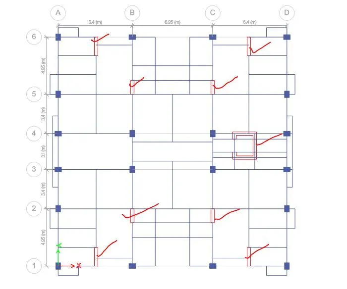
- Shear wall is provided approx. 2% of plinth area i.e. 8mm2
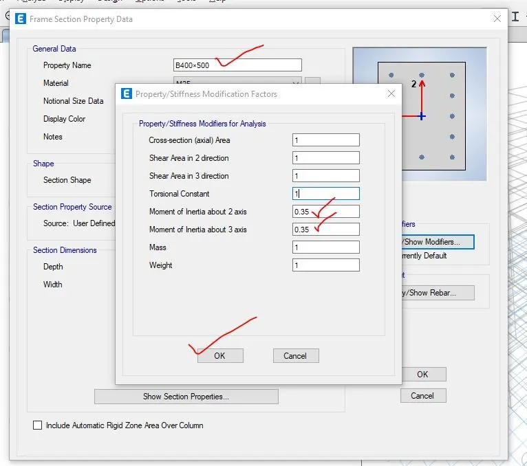
- Stiffness modifier of column, beam and shear wall is 0.7, 0.3 and 0.7 respectively.
1.2.2 Calculation brick wall load and floor finishing
Density of ACC block= 6kN/m
Density of cement mortar= 20kN/m
Thickness of wall= 0.15mm
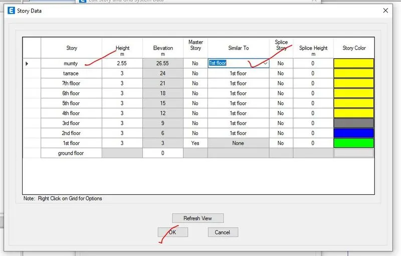
Height of the wall= 3-0.45= 2.55m
Weight of wall= (2.55×0.15×6) = 2.295 kN/m
Assuming thickness of plastering=0.024m
Load for plastering= (2.55×0.024×20) = 1.224 kN/m
Total brick wall load= 2.295+1.224= 3.519 kN/m which is nearly equal to 3.6 kN/m.
Floor finishing= 1.2 kN/m3
1.2.3 Time factor calculation
As per IS 1893:2016, clause-7.6.2 (c), page no-21,
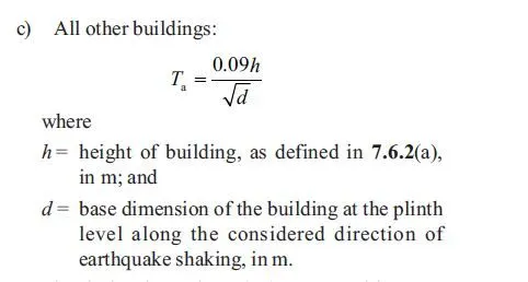
Height of the building=26.55m
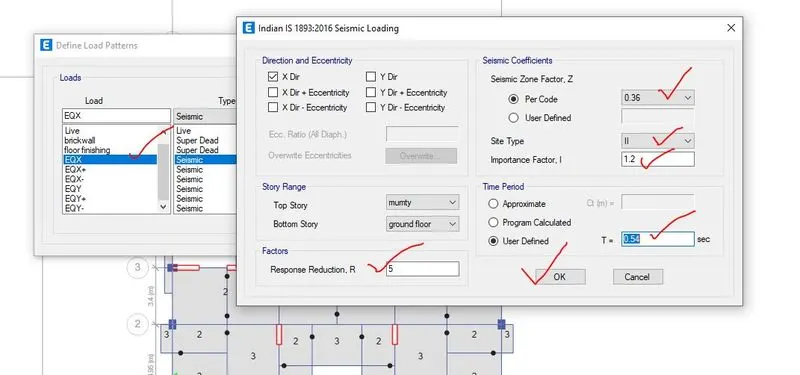
Time factor in y direction where d=19.8m, Tx=((0.09×26.55)/square root(19.8))= 0.5376=0.54
Time factor in x direction where d=19.75m, Tx=((0.09×26.55)/square root(19.75))= 0.537=0.54
1.2.4 Shape factor calculation for response spectrum analysis
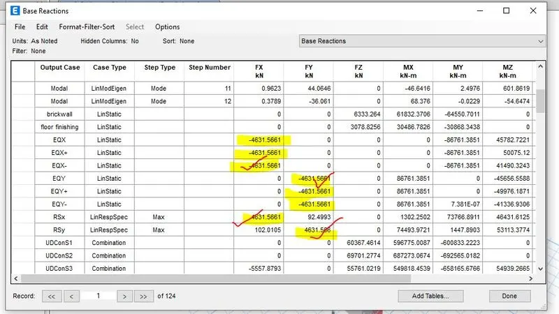
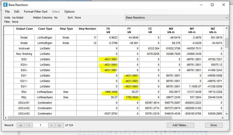
Shape factor in x direction= (4631.5661/1966.3006)×9806.5= 23099.29
Shape factor in x direction= (4631.5661/1782.9692)×9806.5= 25474.44
2.1 Stepwise Procedure in modelling, analysis and design of the G+7 residential building
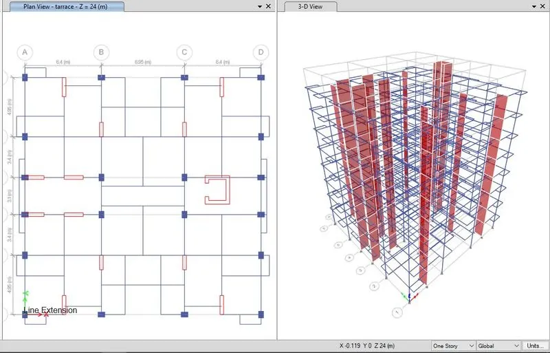
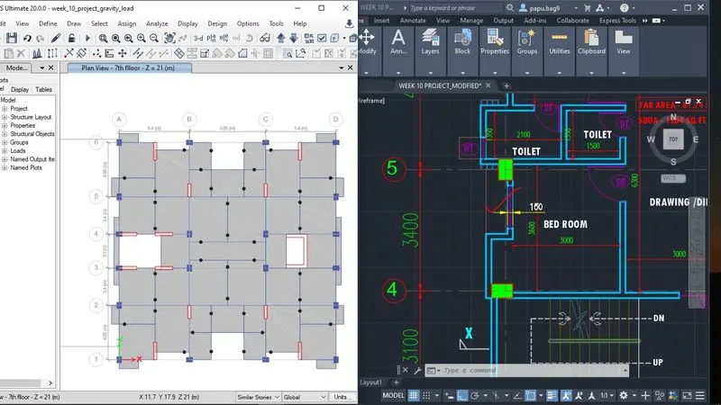
Step-1- First of all, from architectural plan i.e. floor plan of every floor with parking details and elevation the location of column and column layout has been drafted by using AUTOCAD and the beam layout of the floor plan has been drafted.
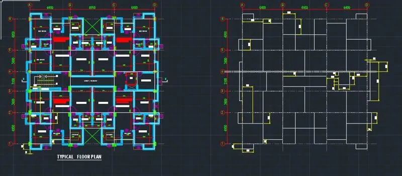

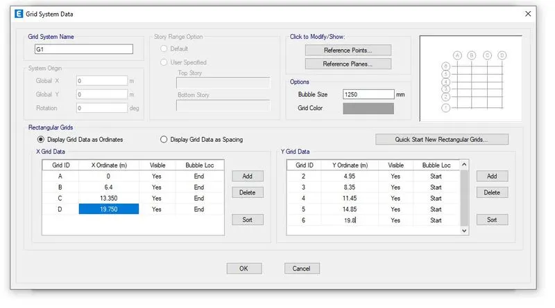
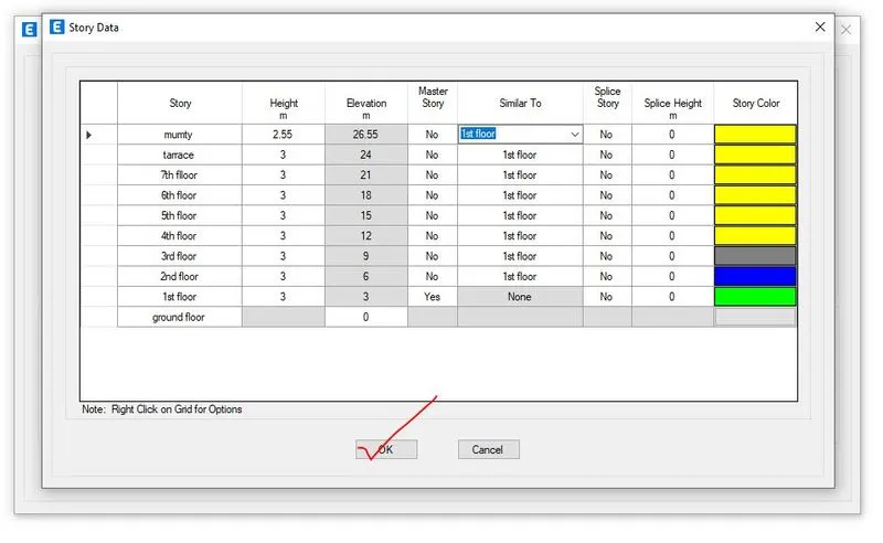
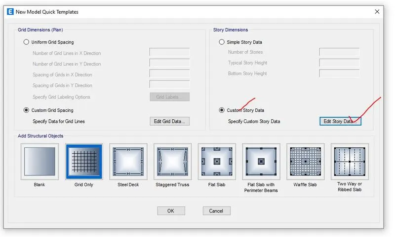
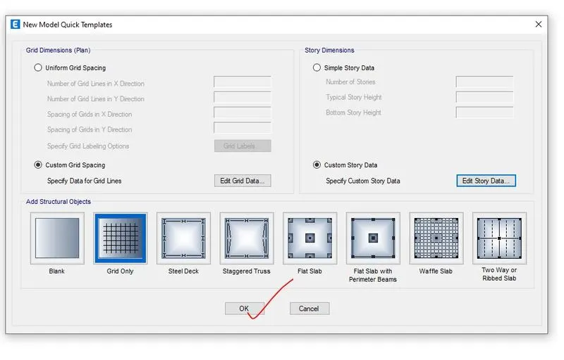
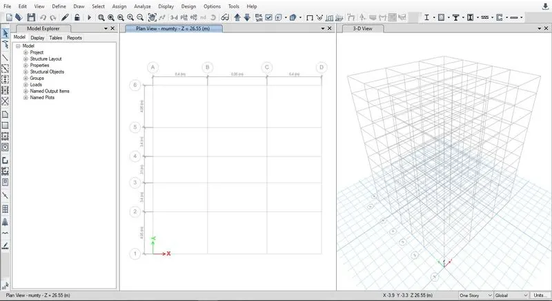
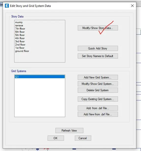
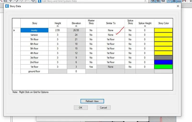
Step-2- After drafting of beam layout and column layout, the grid line has been drafted according to the column placement with proper dimension and storey data has been added in this step.
Step-3- After proper beam, column layout and grids patterns, location of shear wall where the 2% of plan area is going to be located has been decided with respect to the parking area and free space in the plan.
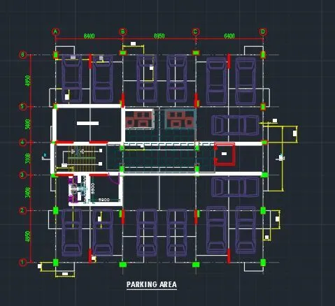
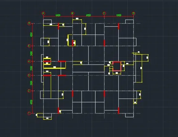
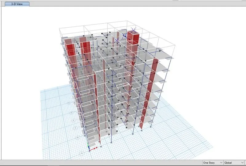
Step-4- After selection of location of shear wall and grids, then the model of G+8 has been modelled on ETABS, firstly the new model has been created with IS 800-2007 and IS 456-2000 and then grids and storey data has been added as per the decided early.
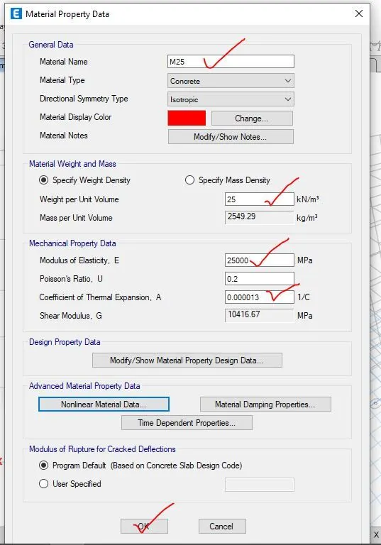
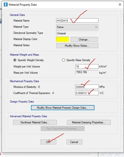
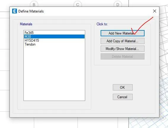
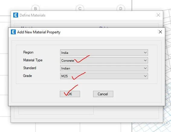
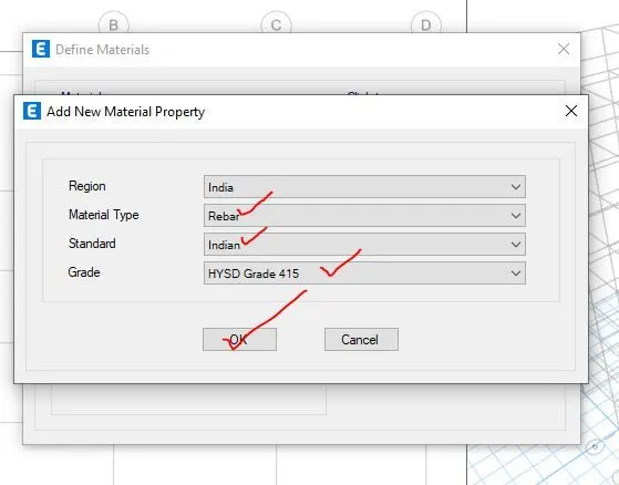
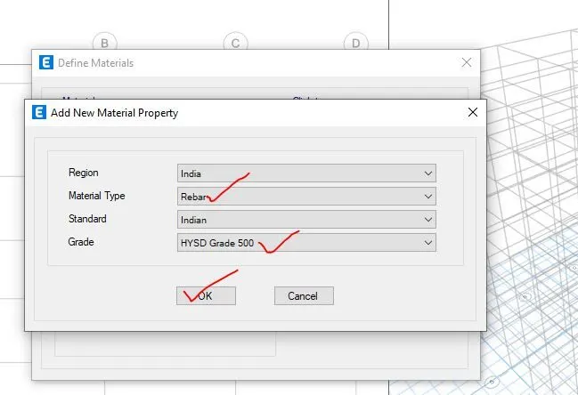
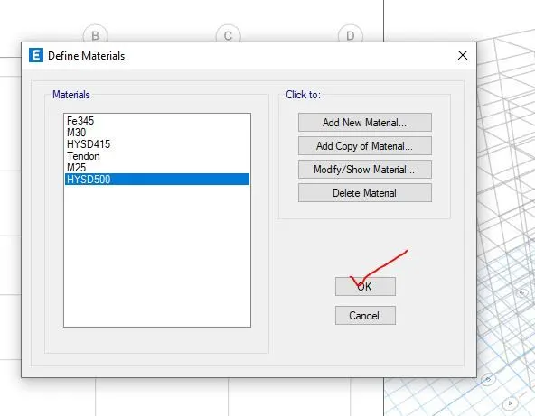
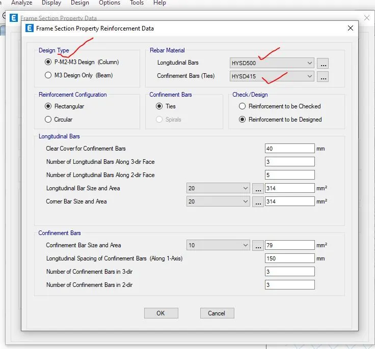
Step-5-After properly completion of grids and storey data, the required material has been added to ETABS i.e. M25 for concrete and Fe415 and Fe500 for rebar.
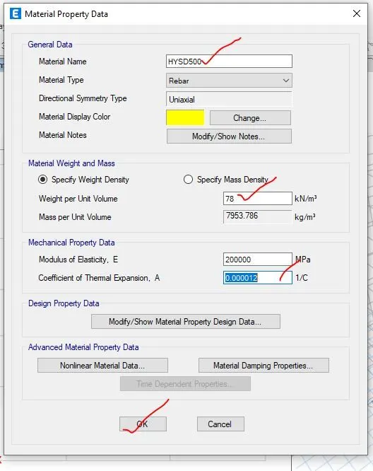
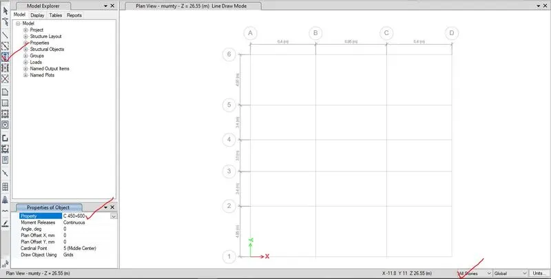
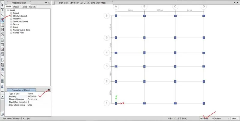
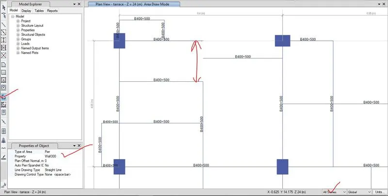
Step-6- the assumed data of concrete column and beam and shear wall has been added i.e. C450×600, C400×500 and wall300.
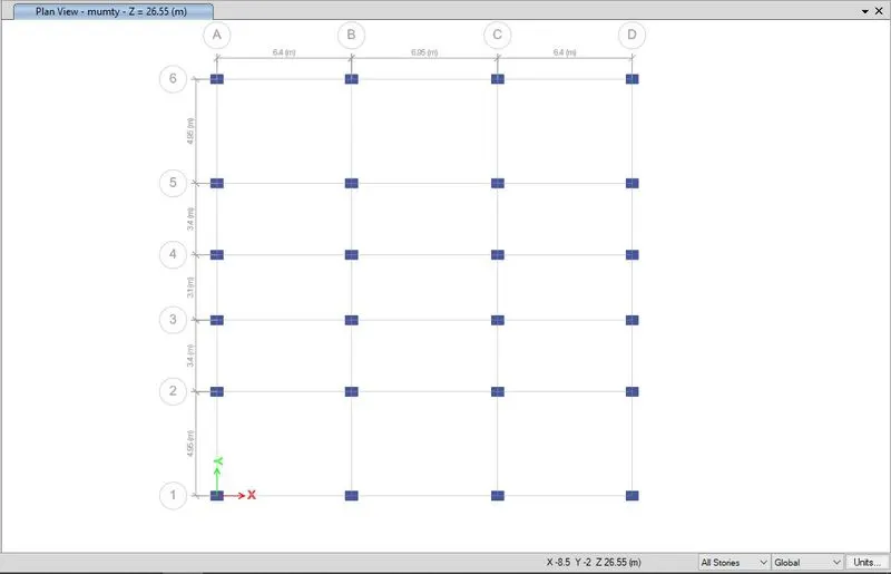
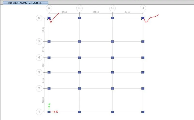
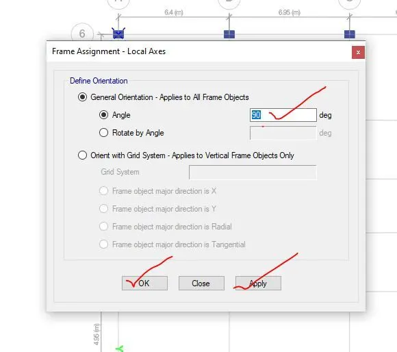
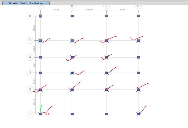
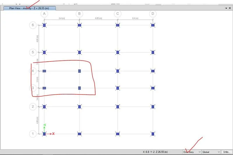
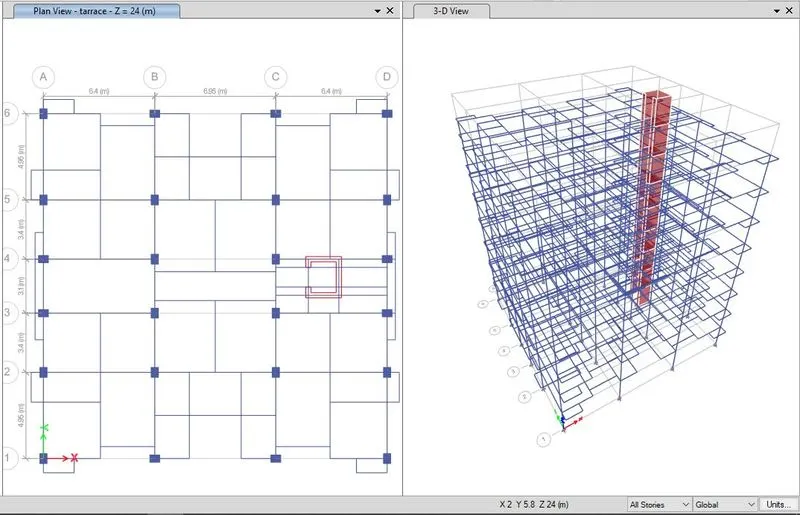
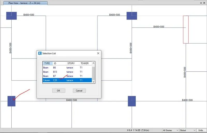
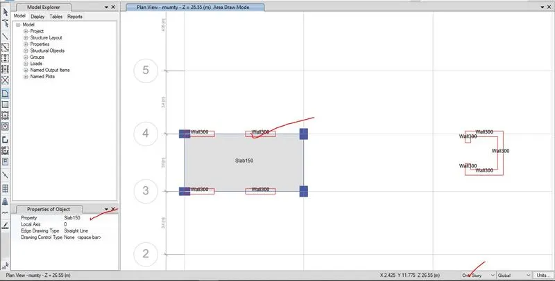
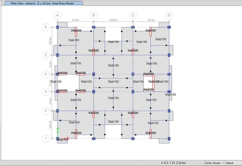
Step-7- Then the column has been added to the required places according to the column layout with proper orientation (i.e. local axis of 90 degree). Column has been added to all the storey.
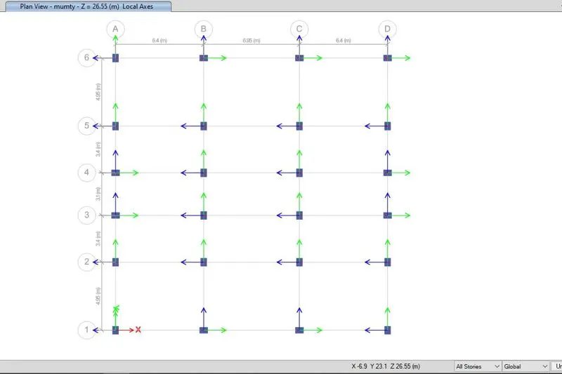
Step-8- According to beam layout, beam has been added to the model where base of model has been left. And at the base, pinned support condition has been assigned.
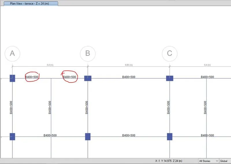
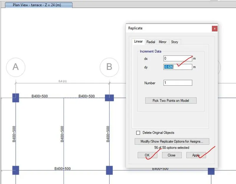
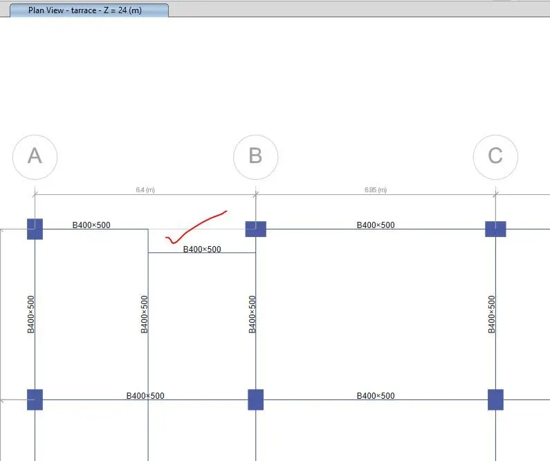
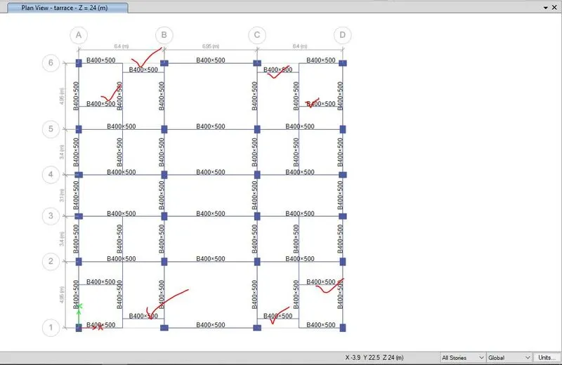
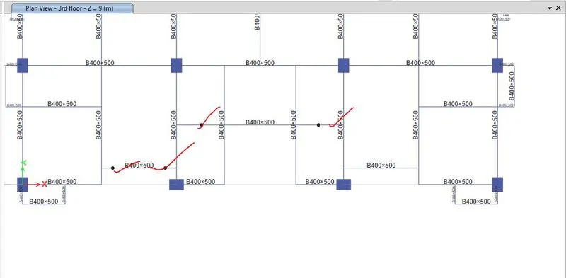
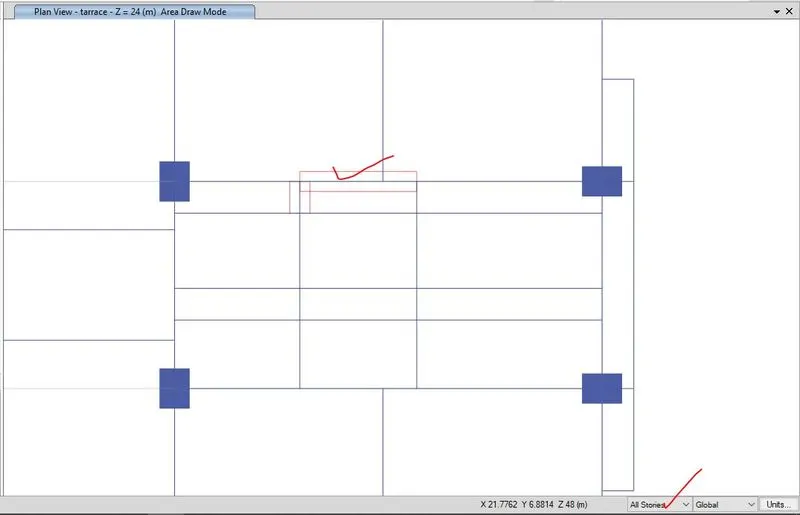
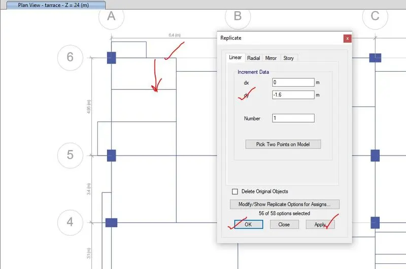
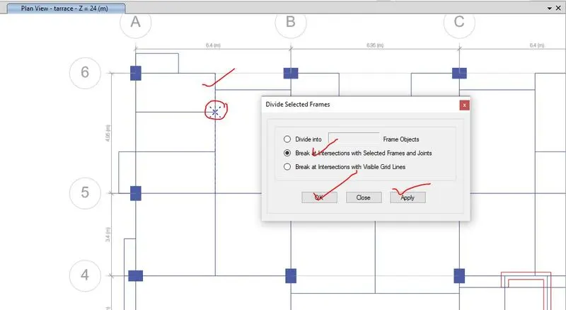
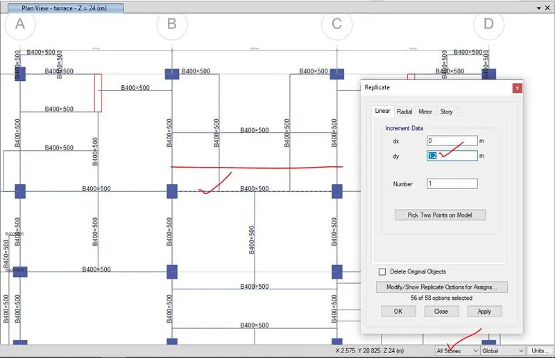
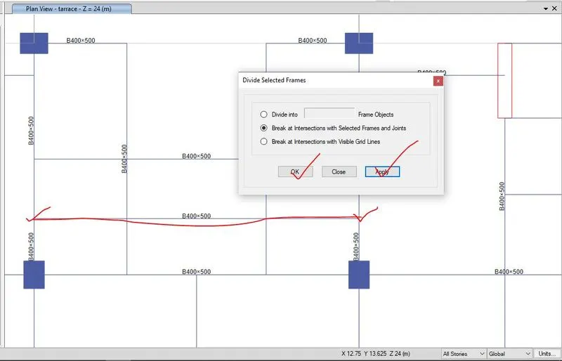
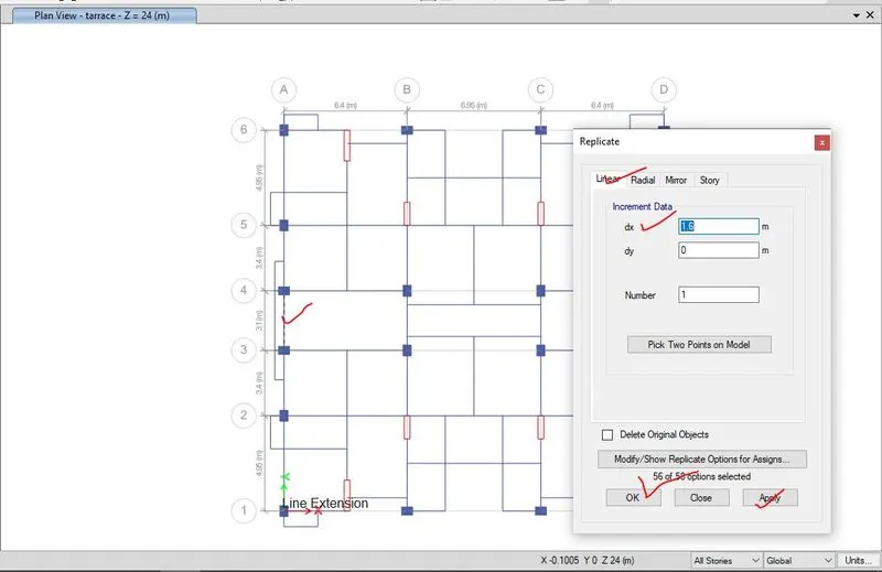
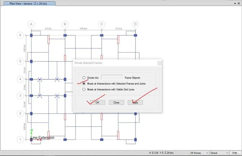
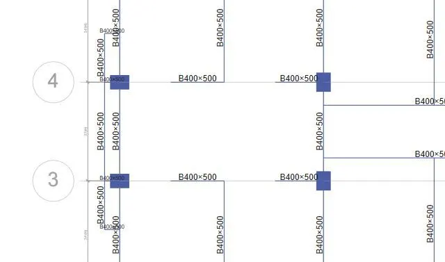
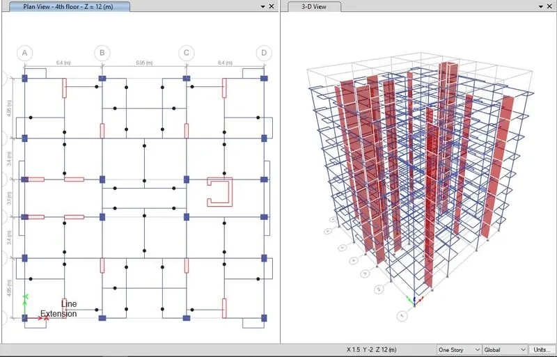
Step-9- By using replicate option, divide selected frame and edit frame option, the secondary beams has been added as mentioned on the beam layout.
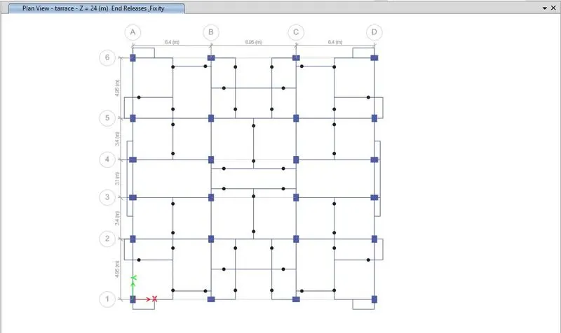
Step-10- After drafting of secondary beams, as per structure requirement, the internal hinged i.e. moment release has been added by using frame assignment.
Assign-à frame assignment à Releases/ partial fixity .
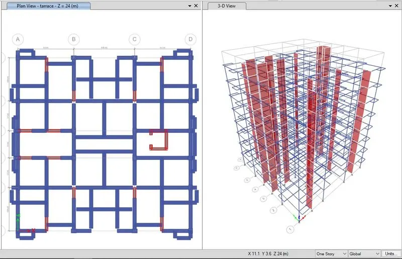
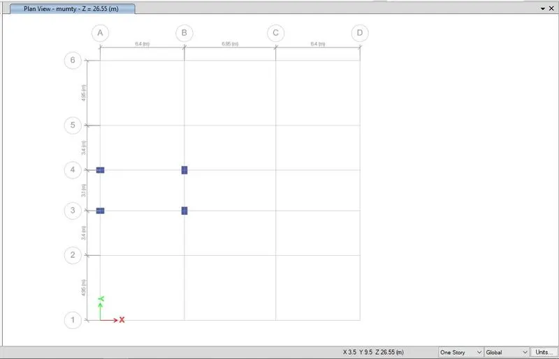
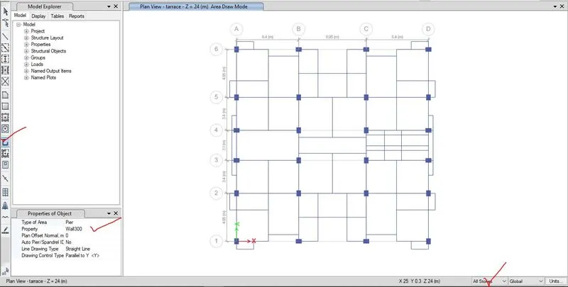
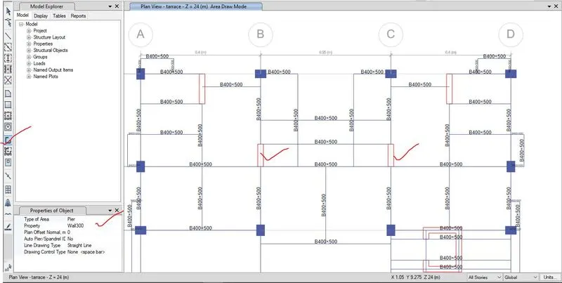
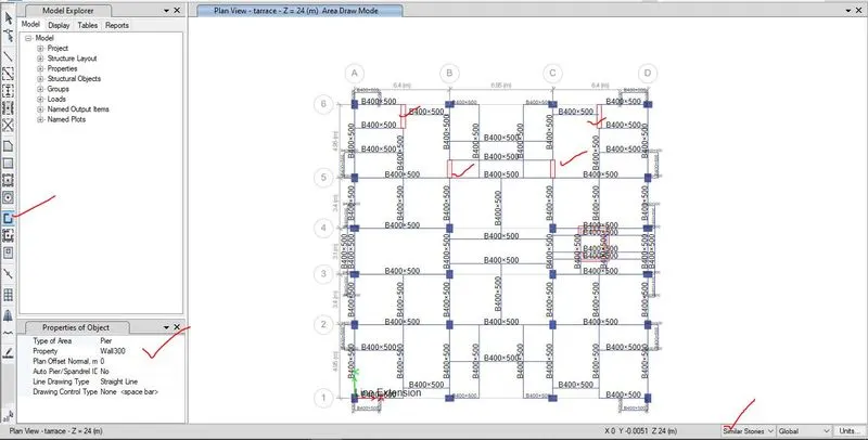
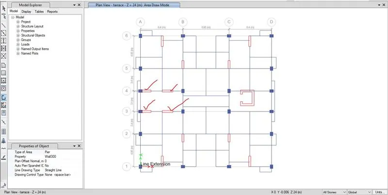
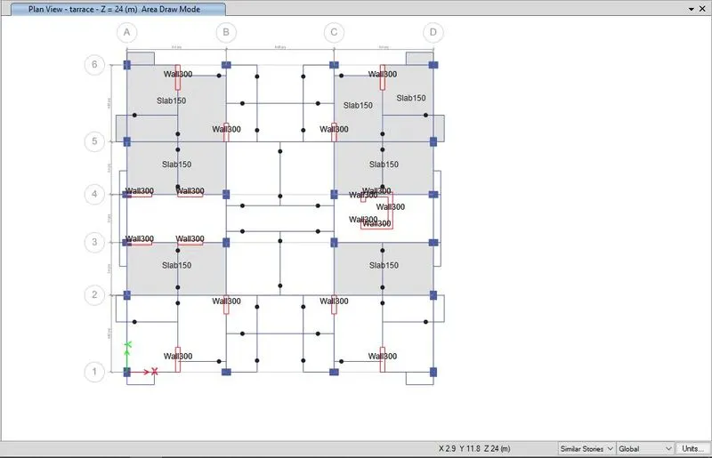
Step-11- by using the quick draw wall option, shear wall of property wall 300 has been drawn according to the plan where shear wall has been decided to place. Before drafting the shear wall if columns and beams are present at the decided location where shear wall is going to be placed, that beams and columns has been deleted.
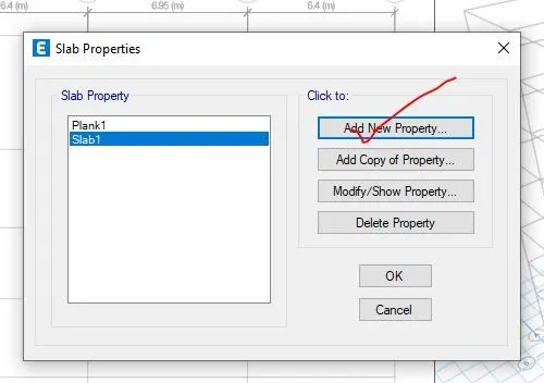
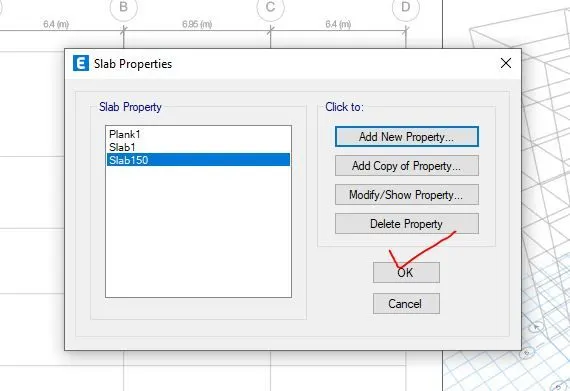
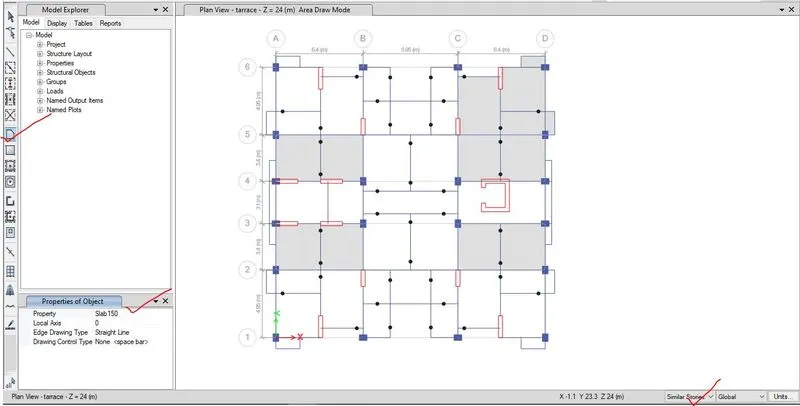
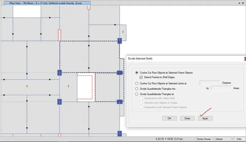
Step-12- Now, slab property has been drafted by using quick drawn floor.
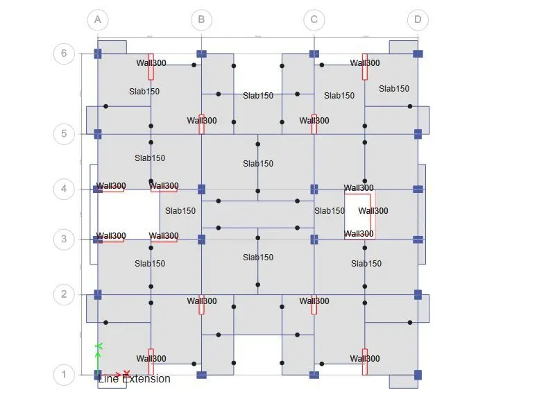
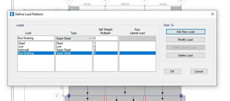
Step-13-After drafting columns, beams and slab property, the load pattern i.e. dead load, live load, brickwall load as super dead type, floor finishing as super dead type has been added for gravity load.
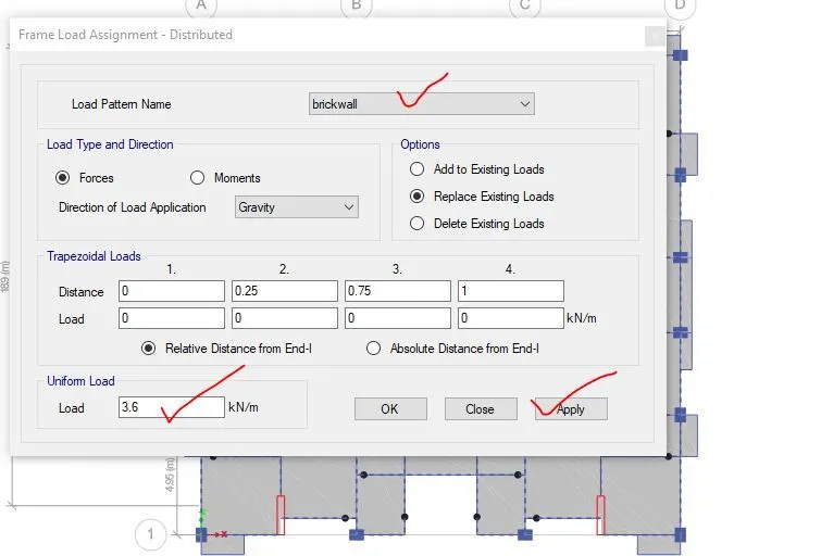
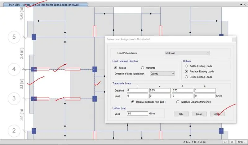
Brickwall load=3.6 kN/m (load due to brick wall and plastering)
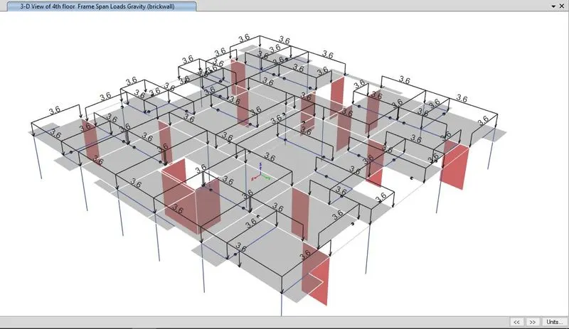
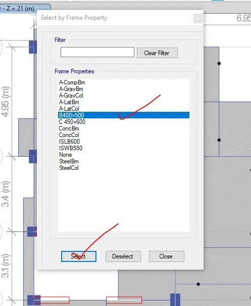
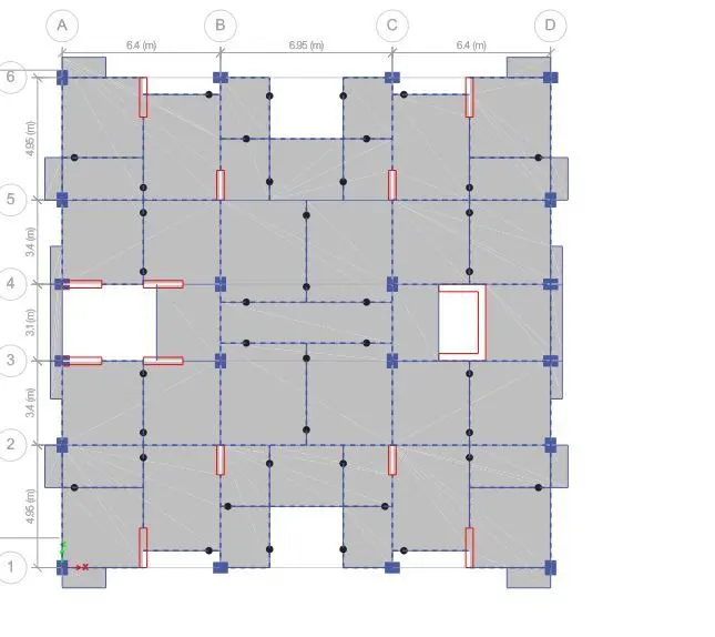
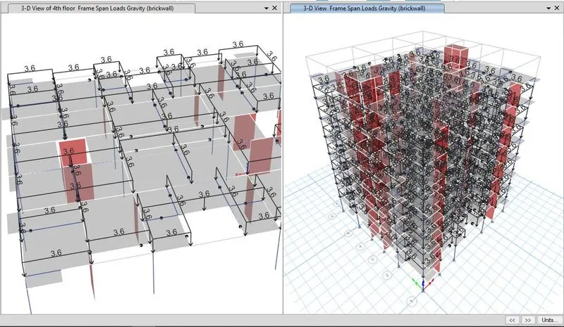
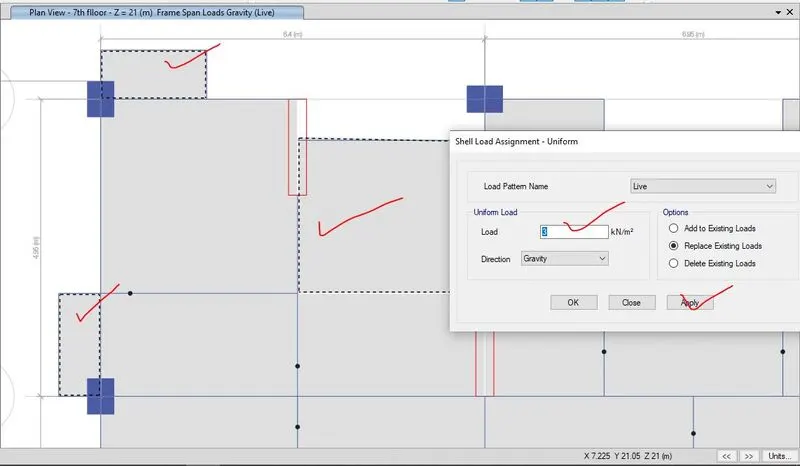
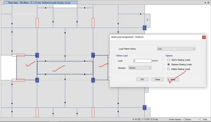
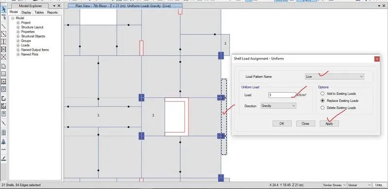
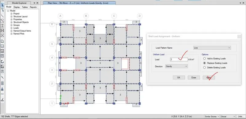
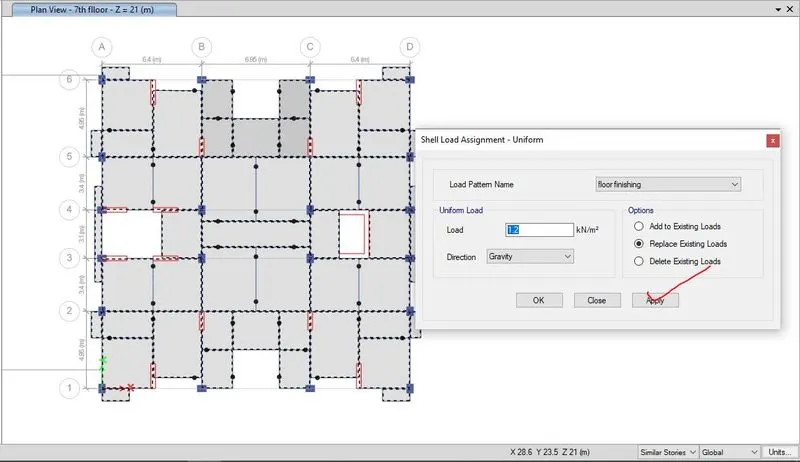
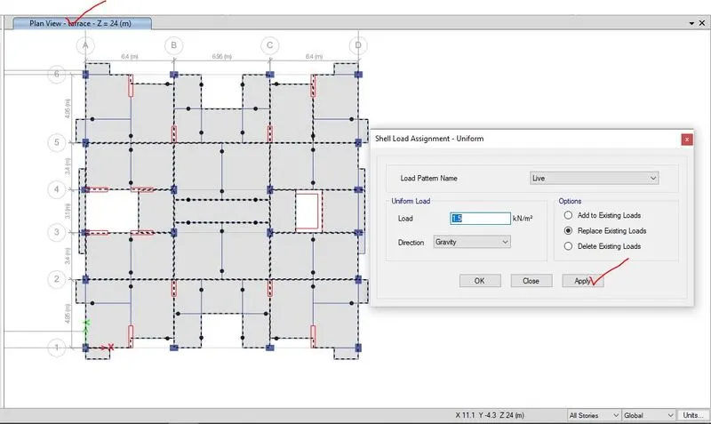
Step-14- then, all the gravity load has been assigned, brickwall load of 3.6 kN/m is assigned on all the beams of all storey by using frame load assignment- distributed load, live load of 3 kN/m has been assigned as shell load assignment- uniform to floor of all the balcony, corridor passage and store room, live load of 2 kN/m has been assigned as shell load assignment- uniform to floor of kitchen and wash room as per IS 875- part -II for live load and floor finishing load of 1.2kN/m has been assigned as shell load assignment- uniform to all the floor except top floor and live load of 1.5 kN/m has been assigned top floor slab.
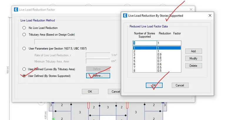
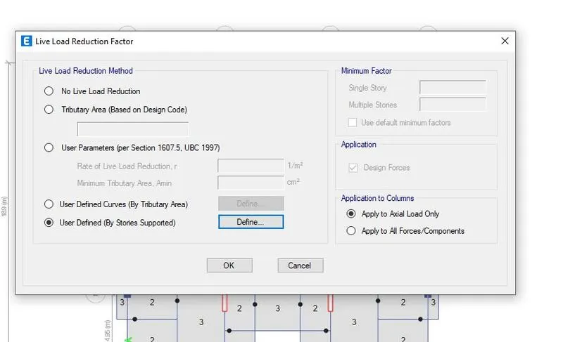
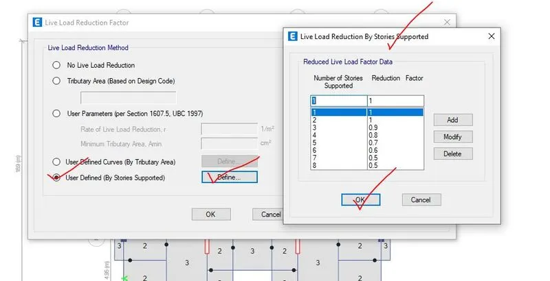
Step-15- Live load reduction factor for each floor as per IS code has added.
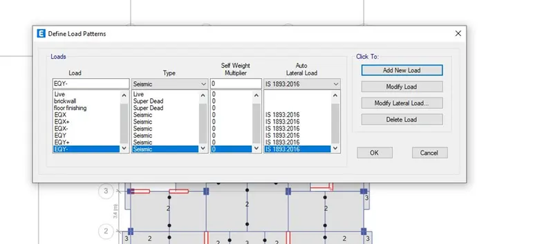
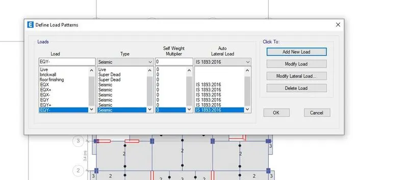
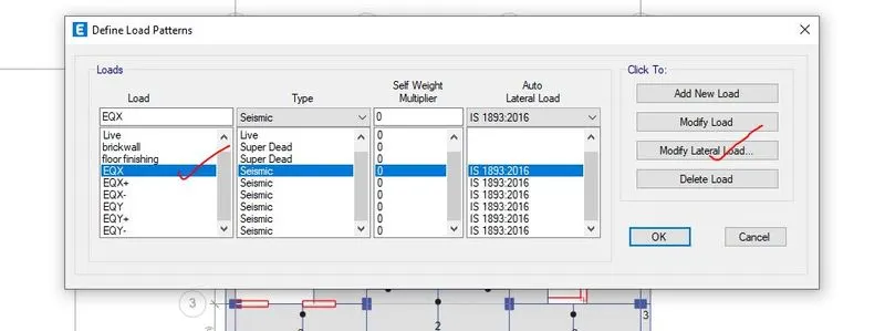
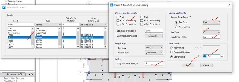
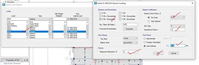
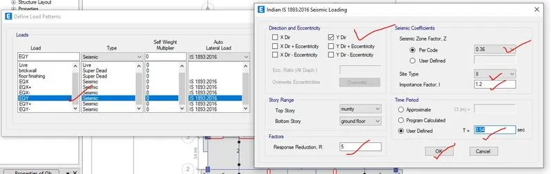
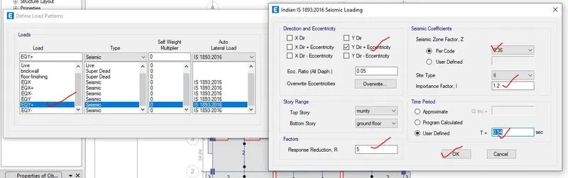
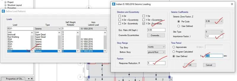
Step-16- Then, load pattern for earthquake load i.e. Eqx, Eqx+, Eqx-, Eqy, Eqy+, Eqy- has been added as seismic load.
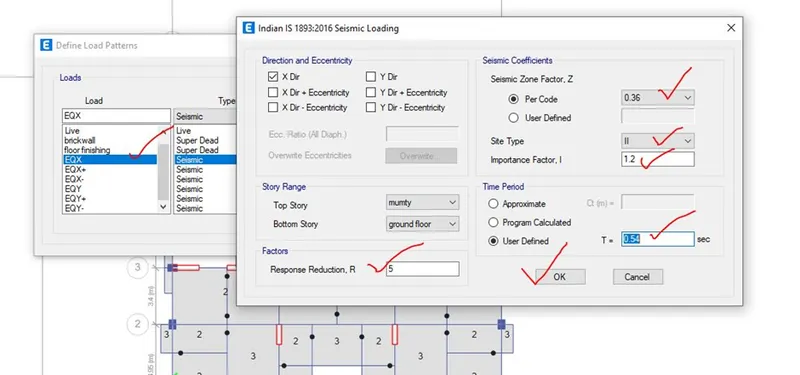
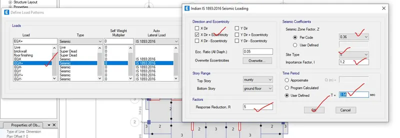
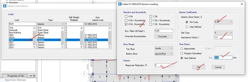
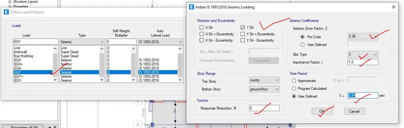
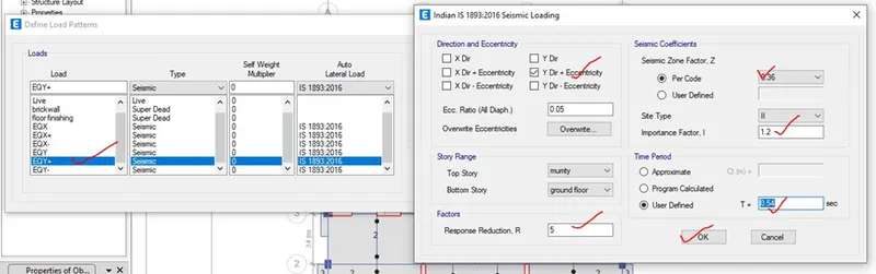
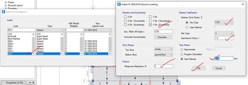
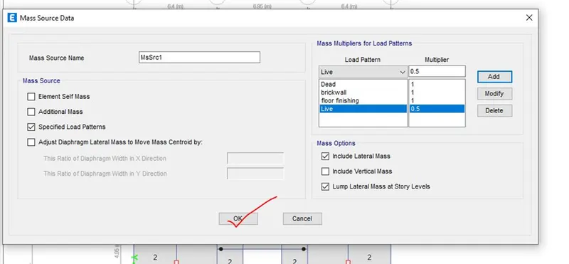
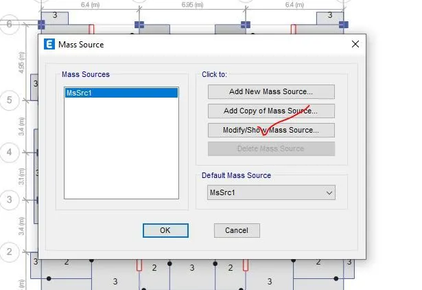
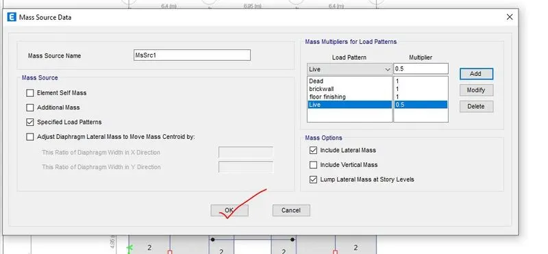
Step-17- then mass sources data for all the load has been added that is given below,
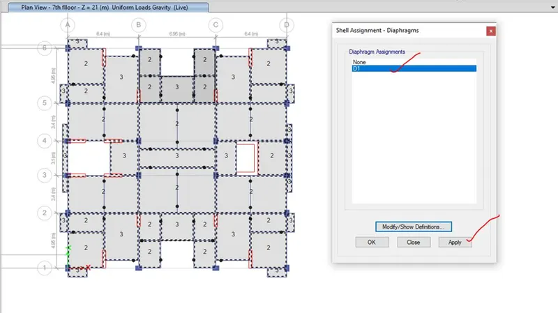
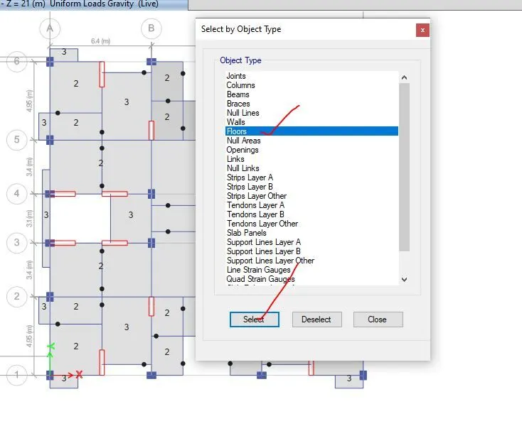
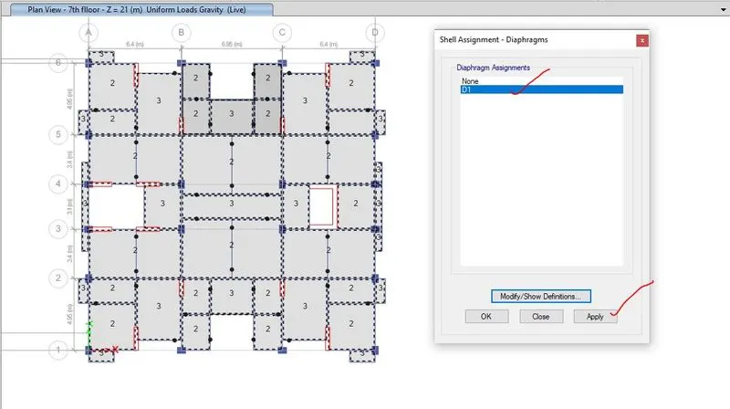
Step-18- Here in this step, diaphragm is added to all the floor after selected all the floor.
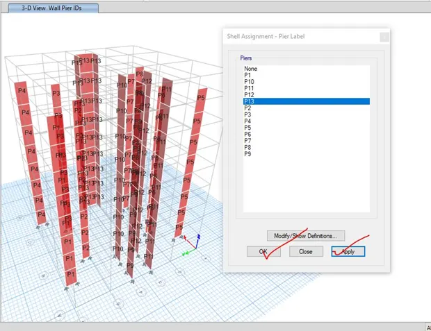
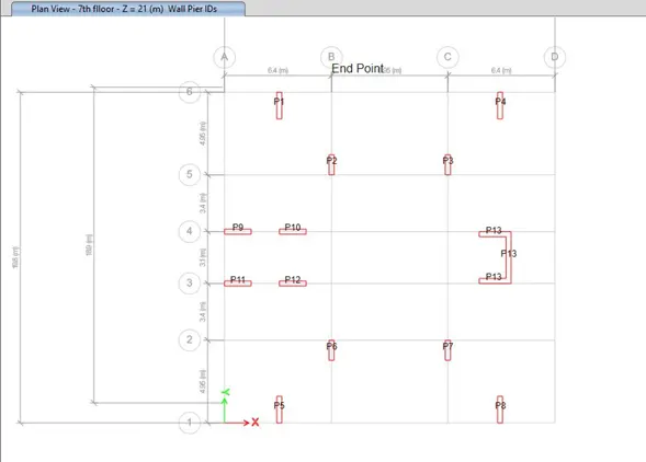
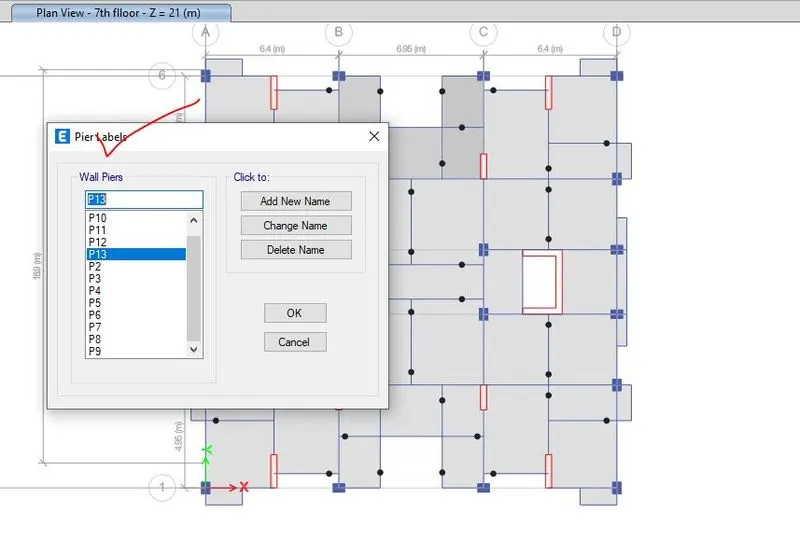
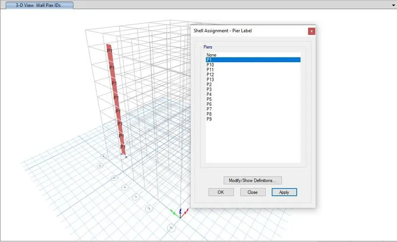
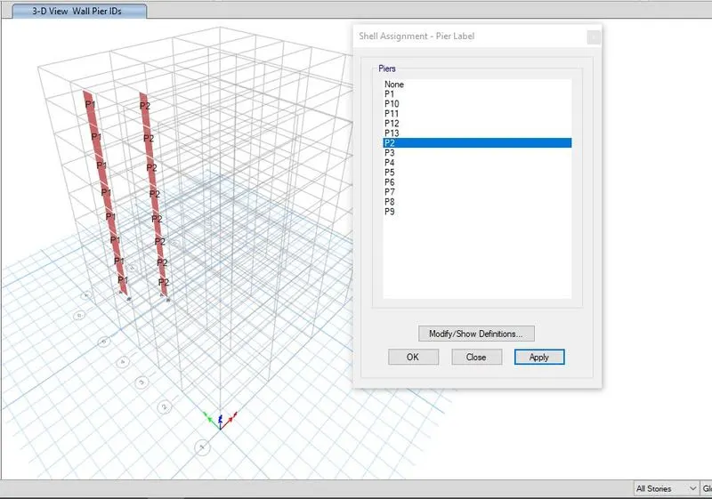
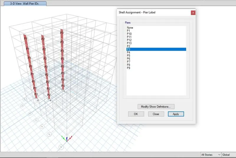
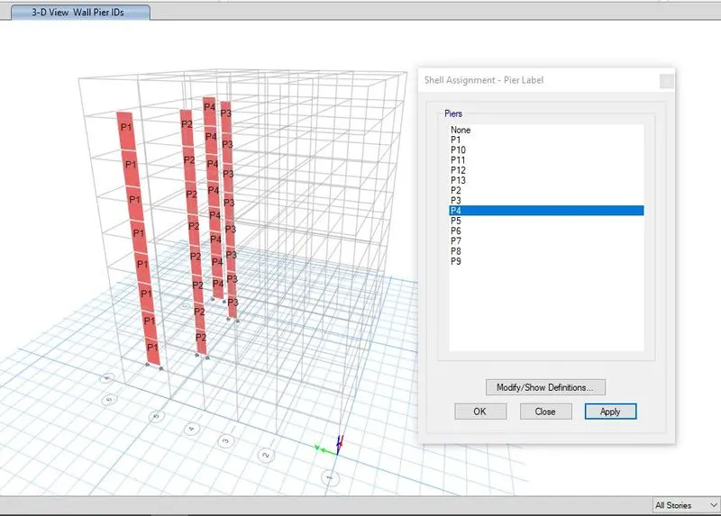
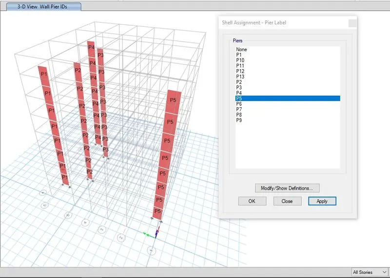
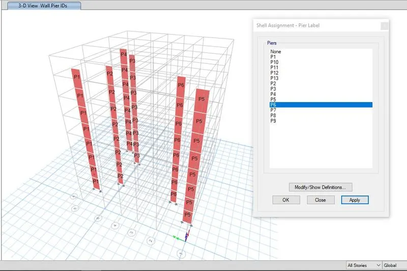
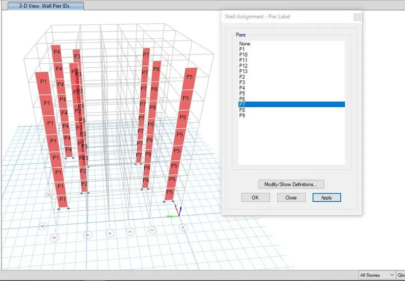
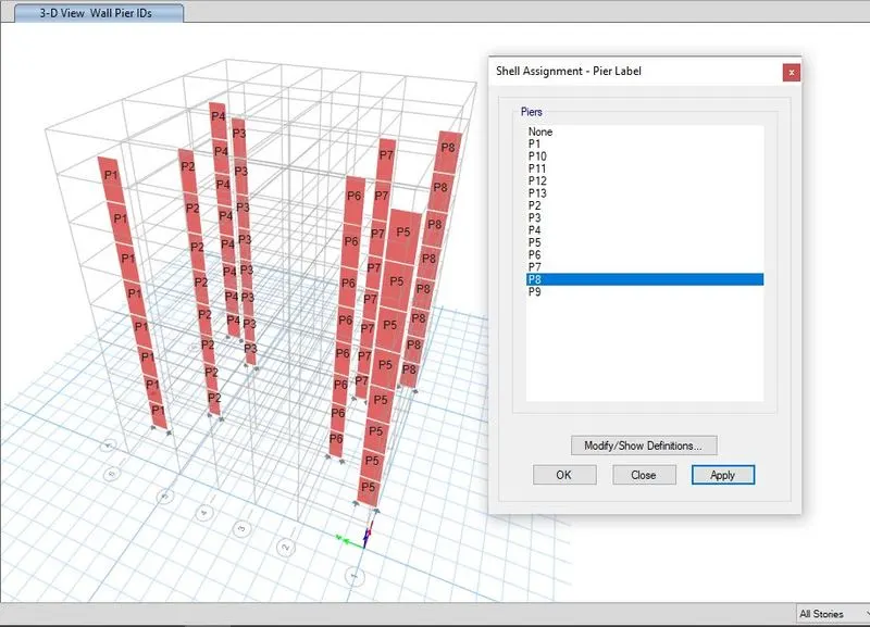
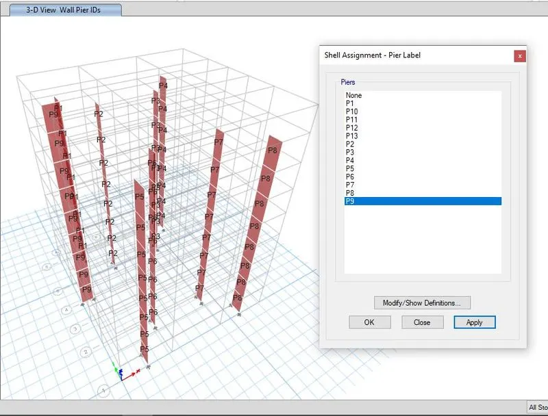
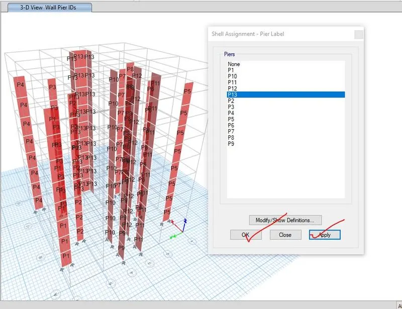
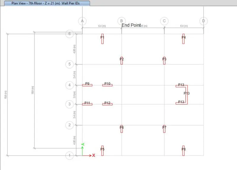
Step-19- 13 pier label has been added as P1, P2, P3, P4, P5, P6, P7, P8, P9, P10, P11, P12, P13 and after addition of pier label, this pier label is assigned to all the shear wall property i.e. wall300.
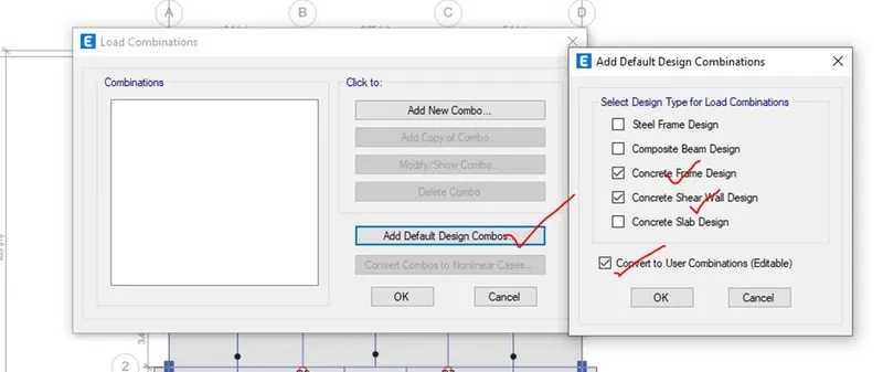
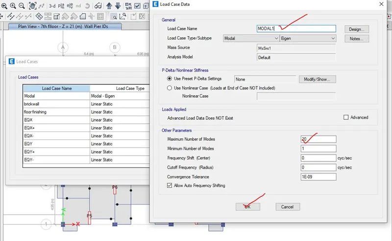
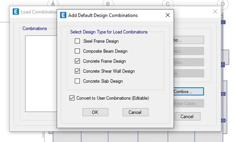
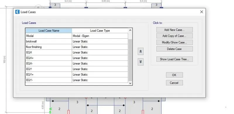
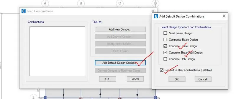
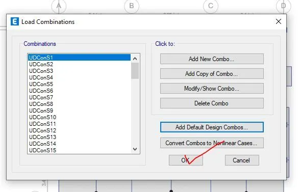
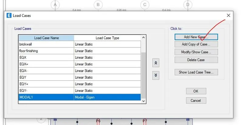
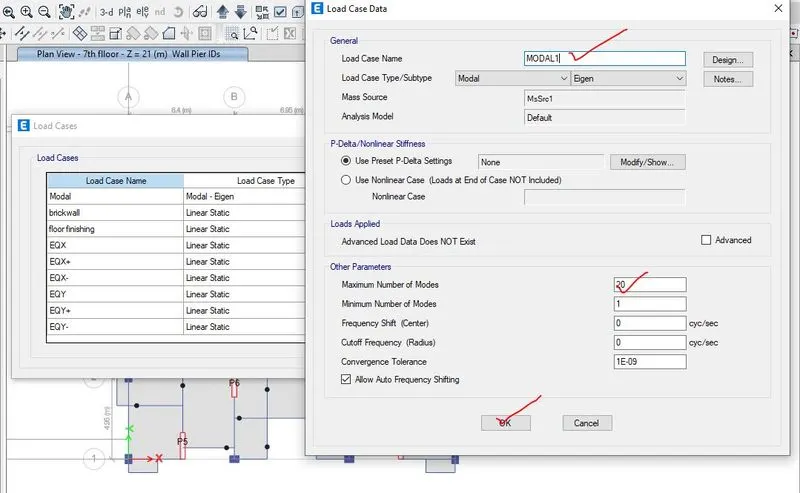
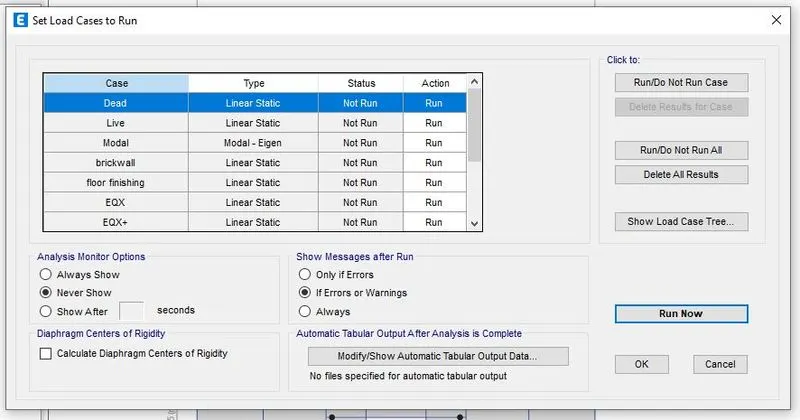
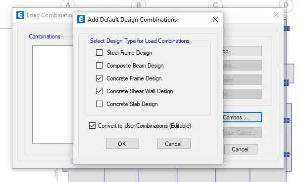
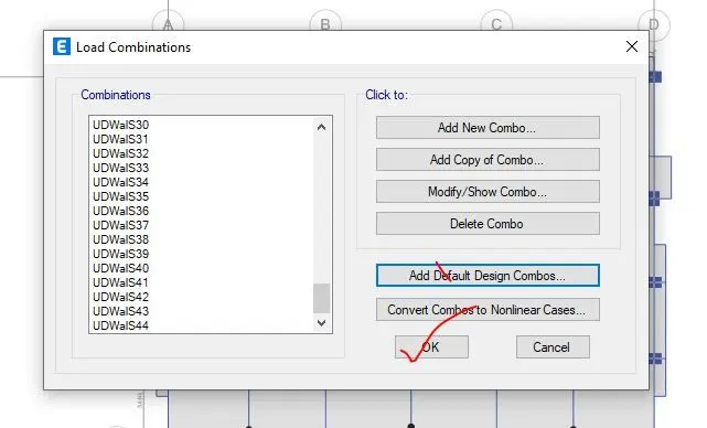
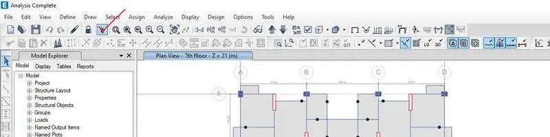
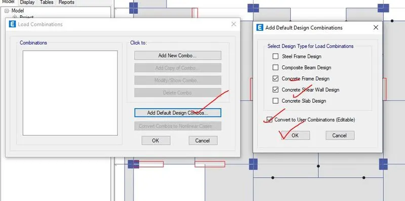
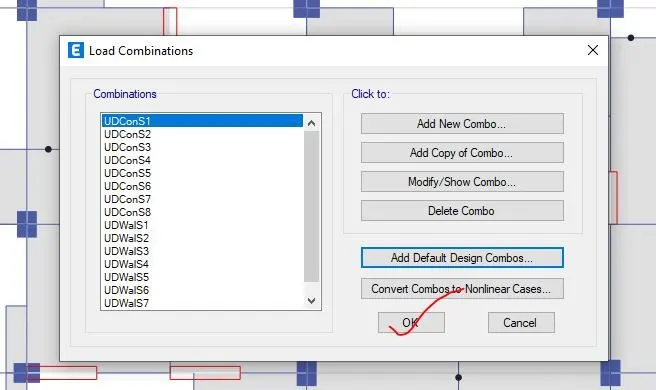
Step-20- After assigning the material property to columns, beams and shear wall, different type of load to model, in the next step load combination has added as default design combination and then for modal analysis, modal property has been added where the mass source has been added. Then, for this load combination of dead load, live load, earthquake load and modal, this model has been analysed by clicking on the run bottom.
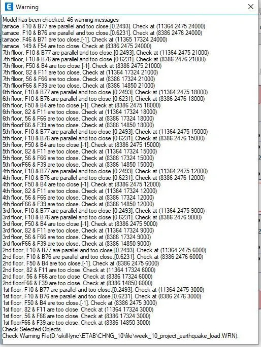
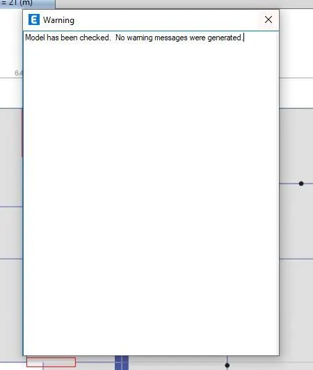
Before analysis, the model has been checked for error and warning and the error has been resolved before analysis.
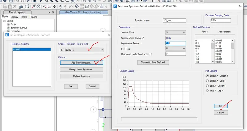
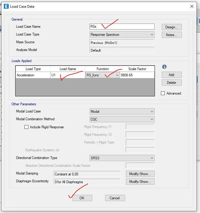
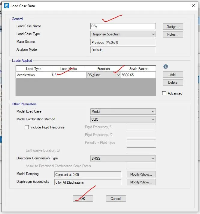
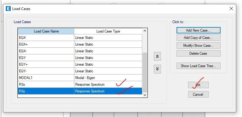
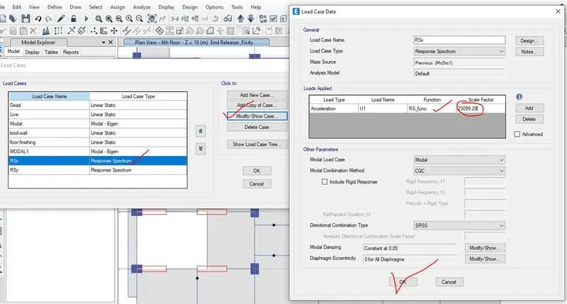
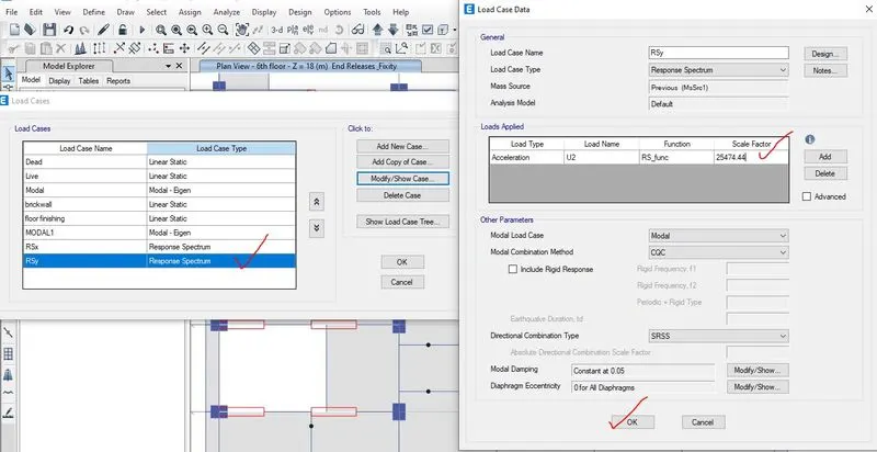
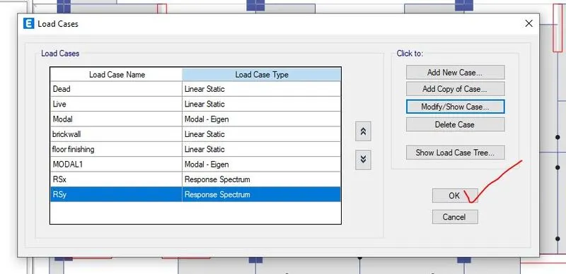
Step-21-then in the next step, for response spectrum analysis, the response spectrum function has been added. After constructing of response spectrum function, two load cased of response spectrum for acceleration in two direction has been added where scale factor is taken as default as it given i.e. 9806.65 which is shown below,
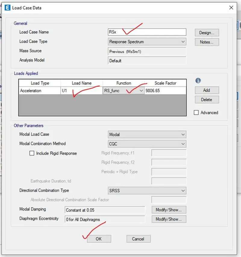
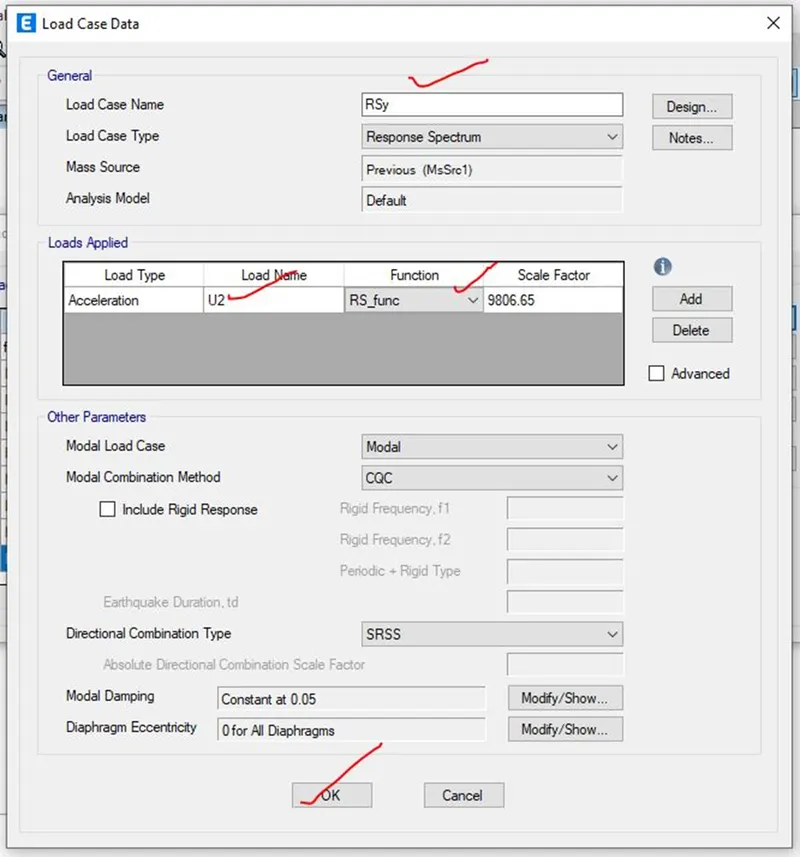
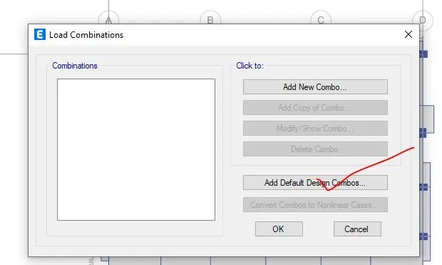
Step-22-for response spectrum analysis for given below loadcases, load combination has been added as default load combo again and once again this model has been analysed by clicking on run bottom.
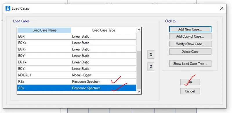
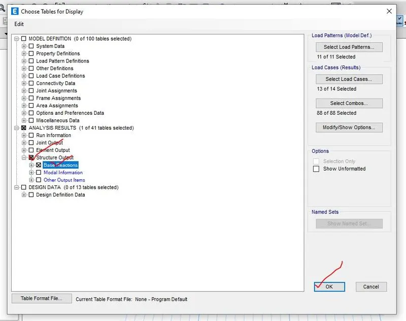
Step-23- From the base reaction data, the scale factor has calculated for the two acceleration of response spectrum i.e. 23099.29 for U1 acceleration and 25474.44 for U2 acceleration.
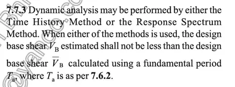
As per clause 7.7.3, page no-23, IS 1893:2016,
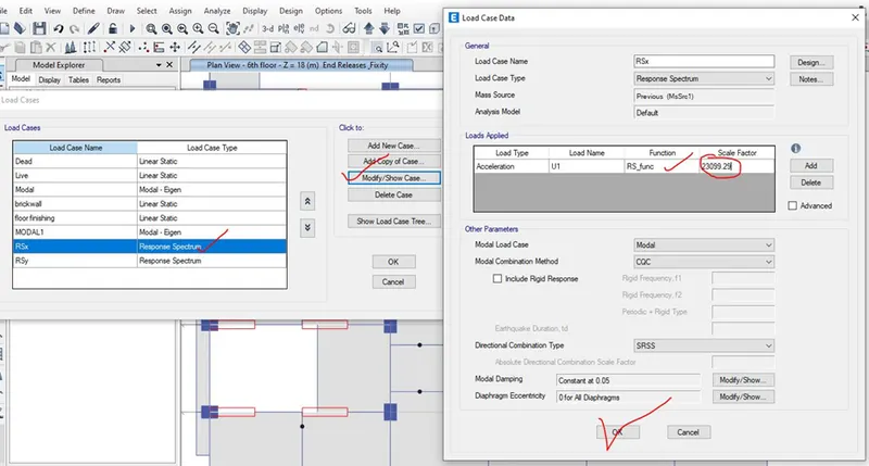
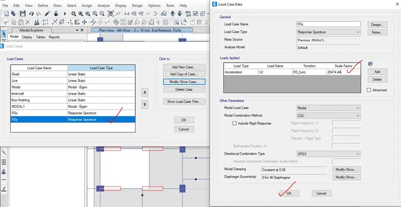
Step-24- After modification of scale factor for two acceleration, this model has been analysed once again where the load cases of earthquake has been deducted and load cased of dead load, live load, modal and response spectrum has been considered and for this load case, load combination has been again modified. And then this model has been analysed once again.
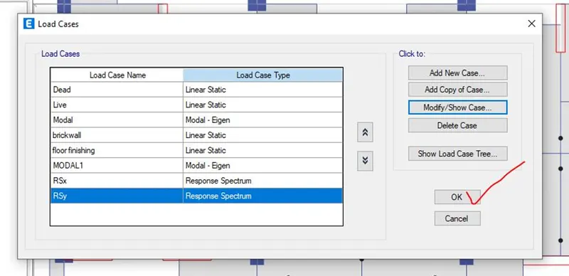
2.2 All the stepwise screenshots in modelling, analysis and design of the G+7 residential building
2.2.1 Stepwise screenshots in modelling of G+7 building in ETABS
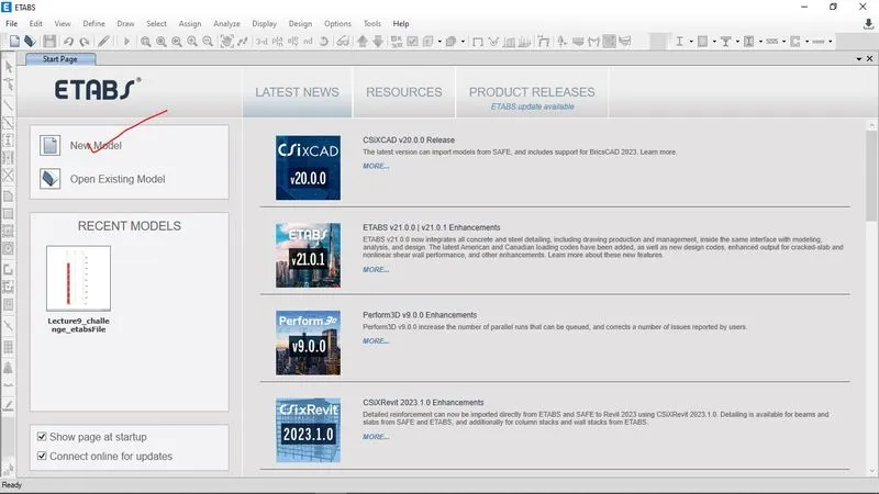
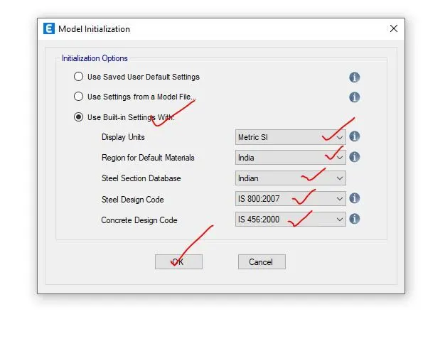
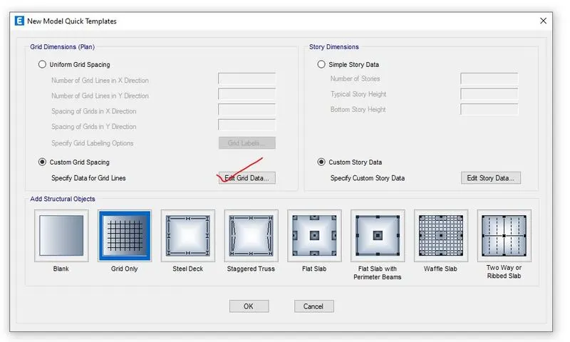
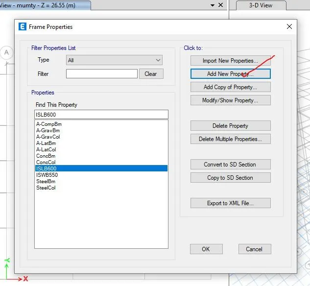
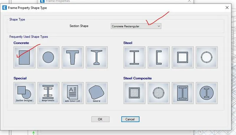
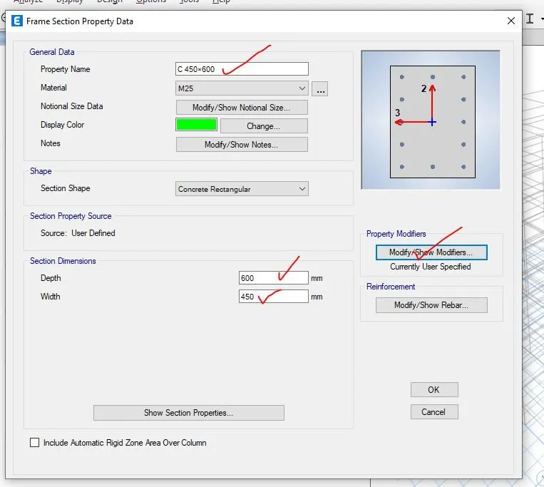
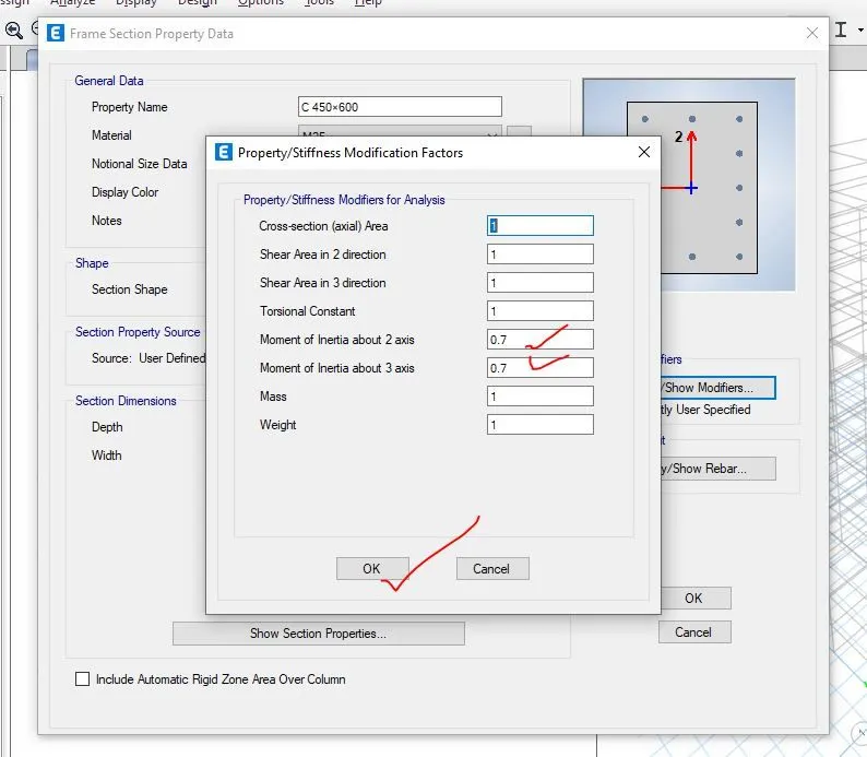
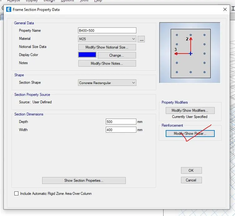
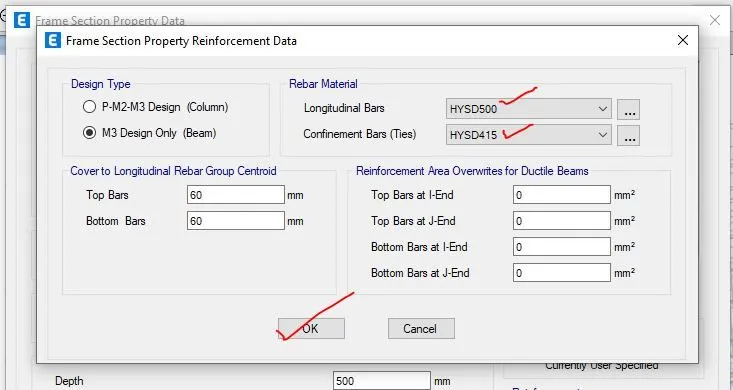
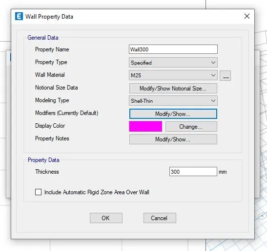
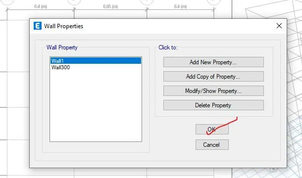
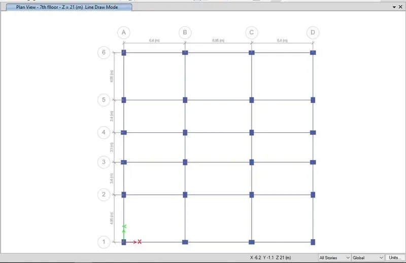
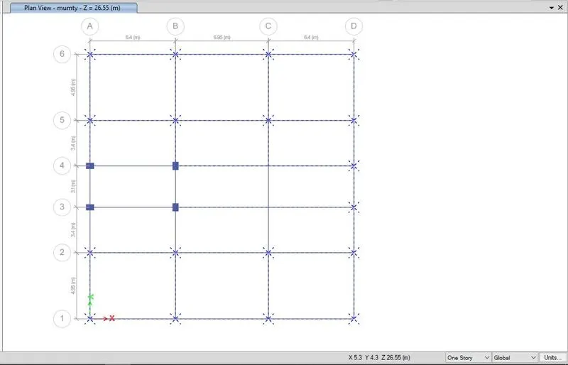
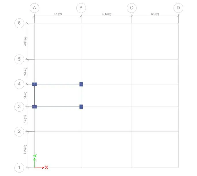
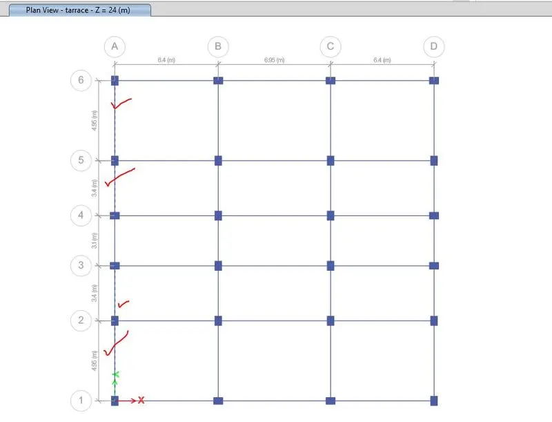
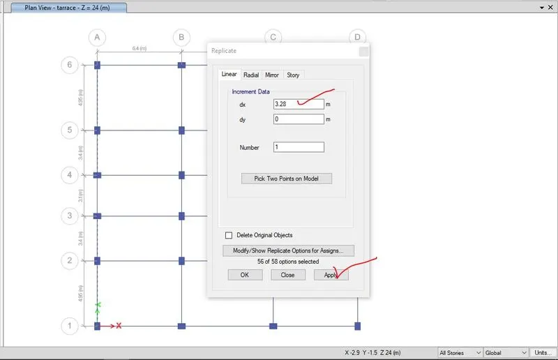
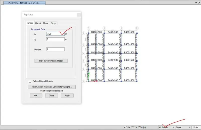
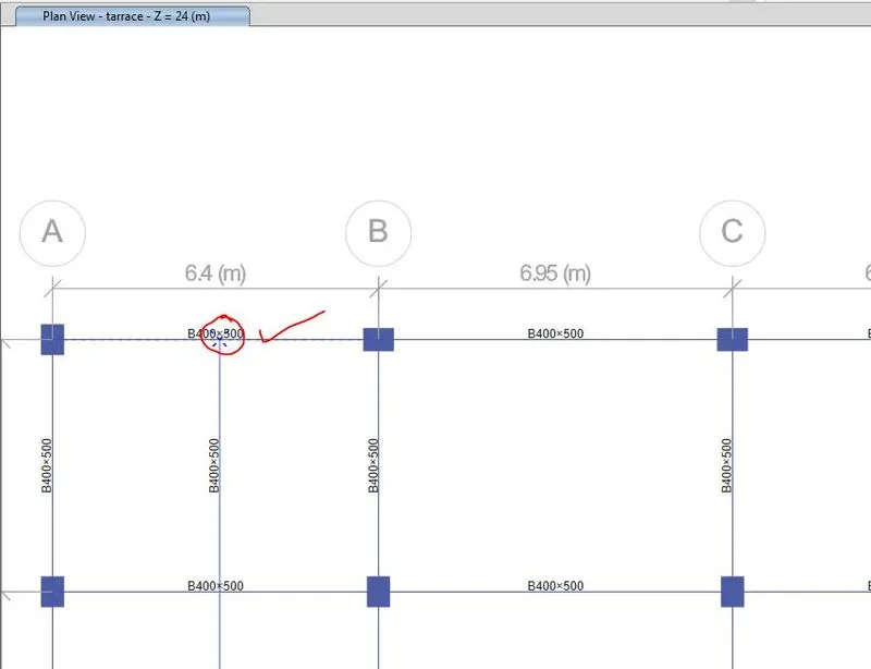
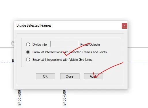
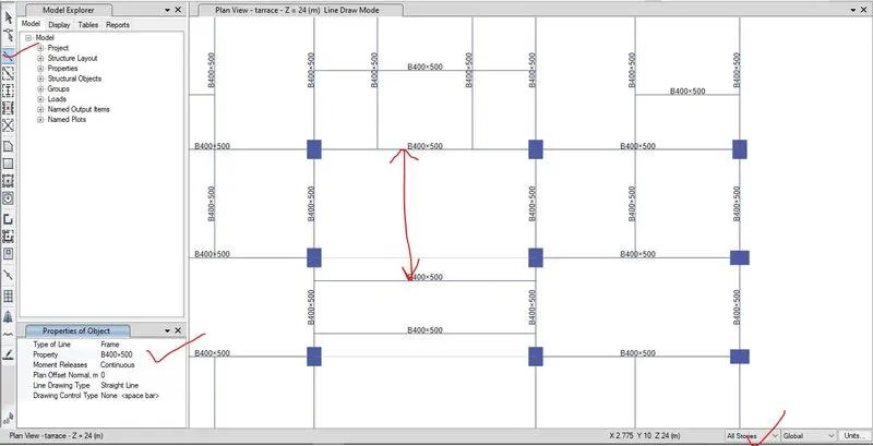
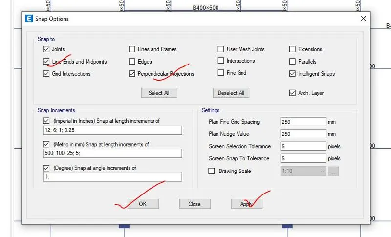
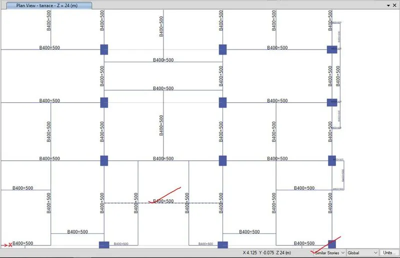
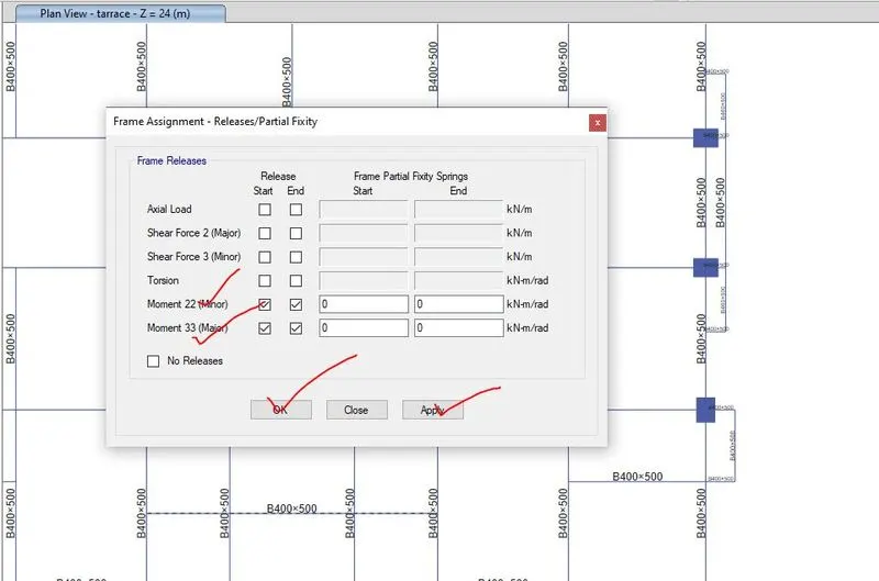
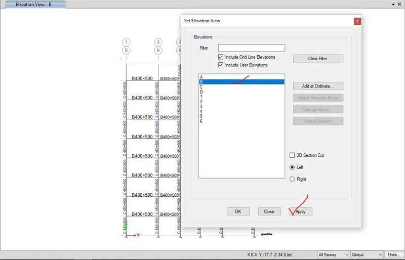
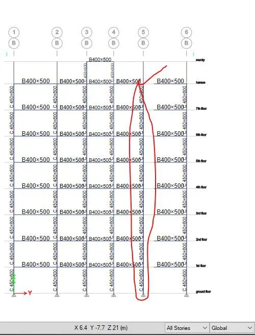
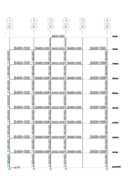
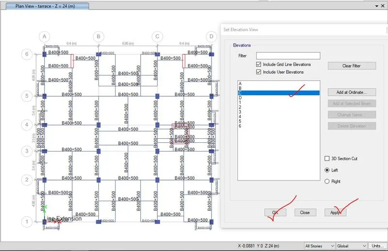
2.2.2 Stepwise screenshots of procedure in defining of load patterns and analysis of G+7 building model in ETABS
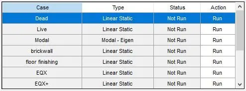
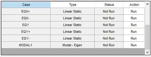
2.2.3 Stepwise screenshots of procedure in analysing of response spectrum and designing of G+7 building model in ETABS
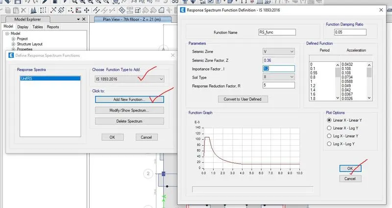
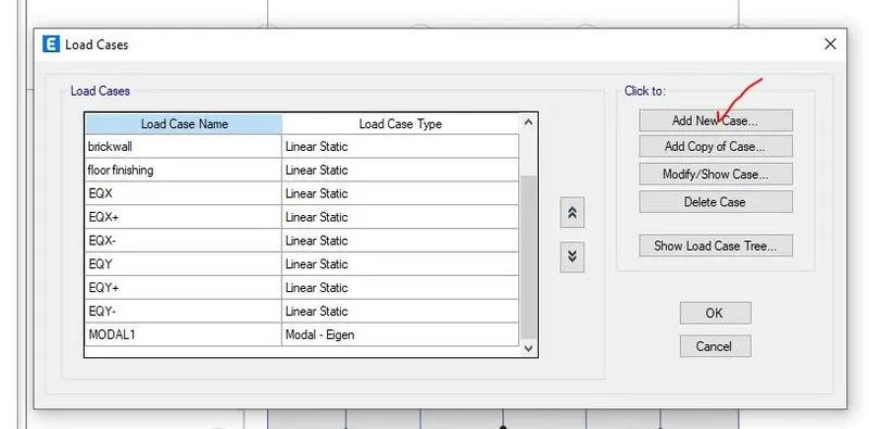
3.1 Results and discussion
3.1.1 Check after analysis,
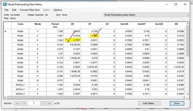
- Modal mass participation for 1st three mode should be atleast 65%- it is acheived in both the direction i.e. in x and y direction.
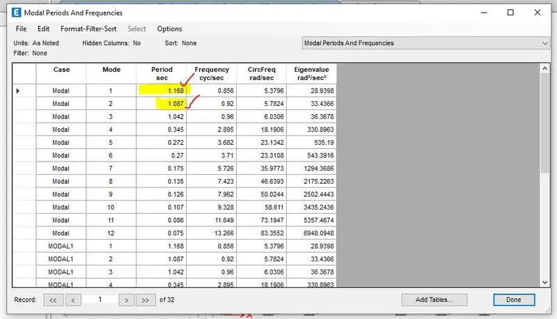
- Time period of Mode 1 and mode 2 deffer by 10%. so it is ok.
- Time period of principal mode is greater than torsional mode.
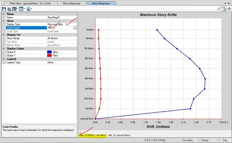
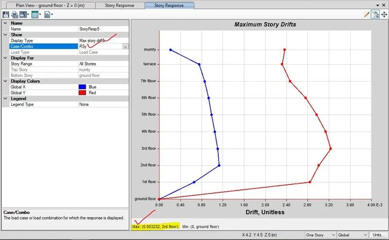
- Inter storey drift is limited to 0.004.
- Base shear share between shear wall and column- it is not a dual system.
3.1.1 NOTE -
The results of modelling, analysis and designing of G+7 residential buildings as per the given data by using ETABS i.e. the .edb file named as “week_10_project_earthquake_load”, “week_10_project_response_spectrum (ELFA)”,” week_10_project_response_spectrum”and ” week_10_project_response_spectrum_analysis” have been uploaded below.