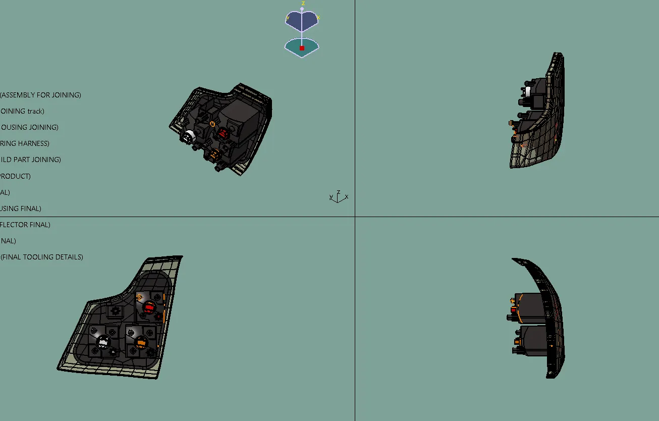
Design and modeling the Complete Tail lamp of the Car
Design and modeling the Complete Tail lamp of the Car
Aim:
To create the a complete design of the tail lamp with all the assembly parts and child parts, also the attachment features by considering the design regulations in CATIA V5 Modelling Software.
Introduction of Car exterior lights
Car exterior lights are a crucial component of an automobile's safety and visibility system. These lights are strategically placed on the outer surface of the car to illuminate the road ahead, signal the driver's intentions, and make the vehicle visible to other road users. Let's explore each type of car exterior light in more detail:
Headlights: Headlights are the primary front-facing lights of a car, located on the front of the vehicle. They are designed to provide illumination during low-light conditions, such as nighttime or in adverse weather like heavy rain, fog, or snow. Headlights ensure that the driver can see the road ahead, potential obstacles, and other vehicles, enhancing safe driving. There are different types of headlights available, including:
- Halogen Headlights: These are traditional incandescent bulbs that emit a bright, white light. They are widely used in many vehicles due to their affordability and ease of replacement.
- LED Headlights: Light Emitting Diode (LED) headlights have gained popularity for their energy efficiency and long lifespan. They produce a brighter and whiter light than halogen bulbs, improving visibility.
- Xenon (HID) Headlights: High-Intensity Discharge (HID) headlights produce an intense, bluish-white light and are often found in high-end vehicles. They offer excellent visibility but can be more expensive to replace.
<!-- [if gte vml 1]>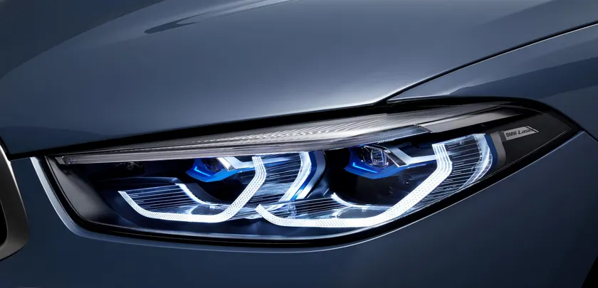
<!--[endif]-->
Daytime Running Lights (DRLs): DRLs are low-intensity lights that automatically turn on when the car is running. They are usually located in the front of the vehicle and are designed to enhance the car's visibility during daylight hours. DRLs help reduce the risk of accidents by making the car more noticeable to other drivers, pedestrians, and cyclists.
<!-- [if gte vml 1]>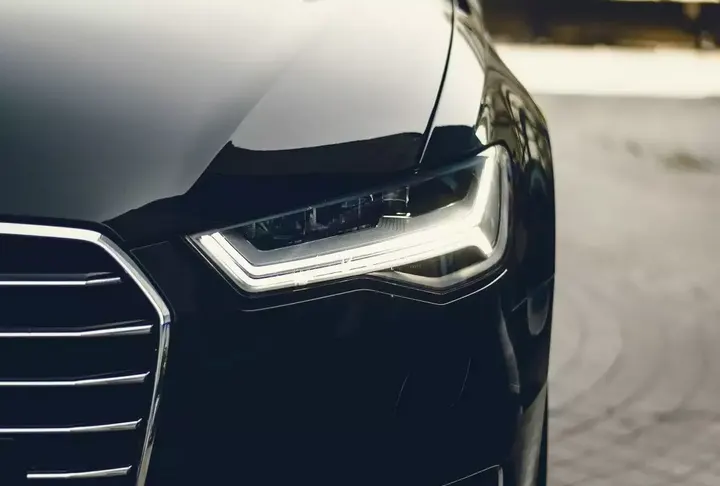
<!--[endif]-->
Fog Lights: Fog lights are positioned lower on the front bumper of the car. They are specially designed to cut through fog, mist, or heavy rain, which can cause regular headlights to reflect the light back, reducing visibility for the driver. Fog lights emit a wide, low beam pattern, helping the driver see the road better in adverse weather conditions.
<!-- [if gte vml 1]>
<!--[endif]-->
Turn Signal Lights (Indicators): Turn signal lights, also known as indicators or blinkers, are typically located at the front and rear corners of the vehicle. When the driver activates the turn signal to indicate a turn or lane change, these lights flash in the direction the driver intends to maneuver. Turn signal lights communicate the driver's intentions to other road users, promoting safe lane changes and turns.
<!-- [if gte vml 1]>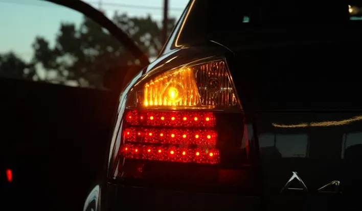
<!--[endif]-->
Brake Lights: Positioned at the rear of the car, brake lights illuminate when the driver applies the brakes. They signal to the drivers behind that the car is slowing down or coming to a stop, giving them time to react. Brake lights are essential for preventing rear-end collisions, as they provide a warning to other motorists.
<!-- [if gte vml 1]>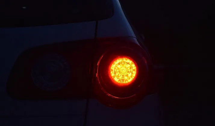
<!--[endif]-->
Tail Lights: Tail lights are also located at the rear of the car and are usually red in color. These lights serve as position markers, making the vehicle visible to other drivers from the back. Tail lights work in conjunction with brake lights and are essential for indicating the presence and size of the vehicle, especially in low-light conditions.
Reverse Lights: White reverse lights are positioned at the rear of the car and illuminate when the driver shifts into reverse gear. These lights provide additional illumination to help the driver see behind the vehicle while backing up, improving safety during parking and maneuvering in tight spaces.
<!-- [if gte vml 1]>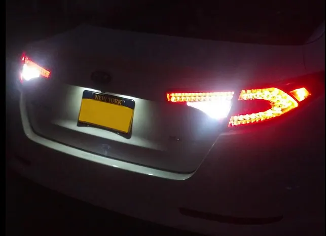
<!--[endif]-->
Side Marker Lights: Side marker lights are small lights placed on the sides of the car, typically near the front and rear fenders. They emit a steady glow and improve the vehicle's visibility from the sides, especially in low-light conditions or when the turn signals are not active.
<!-- [if gte vml 1]>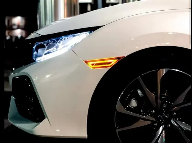
<!--[endif]-->
License Plate Lights: License plate lights are small lights that illuminate the car's license plate, ensuring it is visible and readable at night. These lights are essential for legal compliance and also contribute to the vehicle's overall visibility from the rear.
<!-- [if gte vml 1]>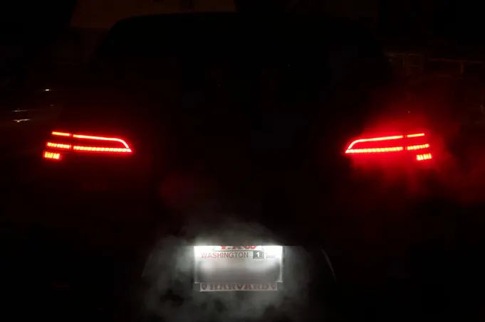
<!--[endif]-->
Car exterior lights are fundamental for safe driving, as they provide the necessary visibility for the driver and communicate important information to other road users. Regular maintenance, such as checking for burnt-out bulbs and keeping the lights clean, is essential to ensure these lights function optimally and contribute to road safety.
Functions of Car Tail Lights:
- Position Markers: Tail lights emit a steady red glow and act as position markers, indicating the presence, size, and width of the vehicle. This helps other drivers determine the relative distance and size of the car, especially during nighttime driving.
- Brake Lights: When the driver applies the brakes, the tail lights intensify their illumination to indicate to the drivers behind that the vehicle is slowing down or coming to a stop. Brake lights are crucial for preventing rear-end collisions.
- Turn Signal Lights: Incorporated within the tail light assembly, the turn signal lights flash in a specific direction to indicate the driver's intention to make a turn or change lanes. This alerts other road users of the driver's intended actions and promotes safe lane changes.
- Reverse Lights: Positioned at the rear of the car, white reverse lights illuminate when the driver shifts into reverse gear. They provide additional illumination to help the driver see behind the vehicle while backing up, aiding in safe parking and maneuvering.
<!-- [if gte vml 1]>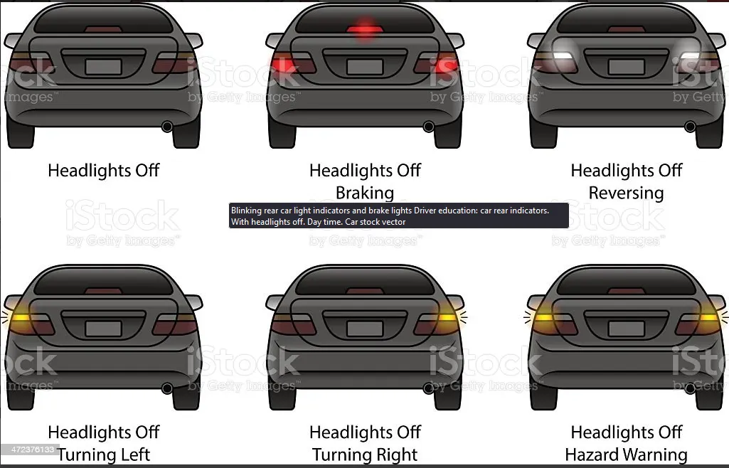
<!--[endif]-->
Methodology:
Creation of the Len’s solid body And Draft Analysis
- Class A Surface: The initial surface design for the lens is referred to as the Class A surface. This surface is intended to have the highest level of quality, as it directly affects the lens's appearance and aesthetics. However, during the design process, it is noticed that the Class A surface is not properly structured and requires improvements.
- Class B Surface: To address the issues with the Class A surface, patchwork is performed to make adjustments and obtain a finer and more refined surface, referred to as the Class B surface. The modifications aim to achieve the desired shape and smoothness, ensuring a higher-quality appearance for the lens.
- Rework at the Edges: Some rework is done specifically at the edges of the Class A surface. This could involve adjustments to the curvature, beveling, or other refinements to improve the overall fit and finish of the lens.
- Offsetting to Create Class B Surface: The Class B surface is obtained by offsetting the modified Class A surface by a certain distance, specifically 2.5mm in this case. This offset helps create the desired thickness and curvature for the lens body.
- Class C Surface: Another surface, referred to as the Class C surface, is created to join the Class A and Class B surfaces together. This surface serves as a bridge or transition between the two surfaces, ensuring a closed volume for the lens solid body.
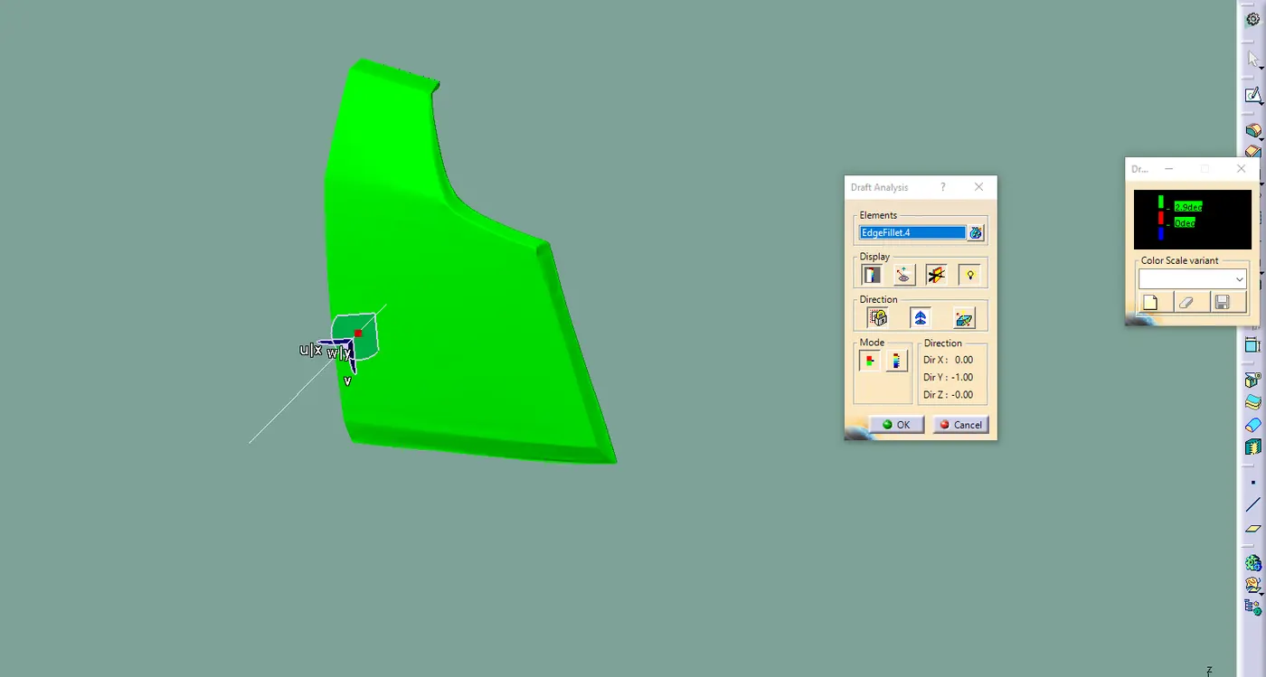
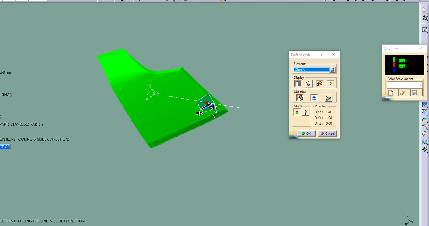
- Draft Analysis and Tooling Direction: The tooling direction is created to determine the draft angle of the lens body. Draft angles are important in the manufacturing process, as they allow for easy removal of the molded part from the mold. This analysis ensures that the lens will clear all directions during the molding process without any interference or difficulties.
- Lens Body as a Closed Volume: Once all the surfaces (Class A, Class B, and Class C) are appropriately designed and joined, the lens body appears as a full green body. This means that it has formed a closed volume, representing a complete and solid lens design.
<!-- [if gte vml 1]>
<!--[endif]-->
<!-- [if gte vml 1]>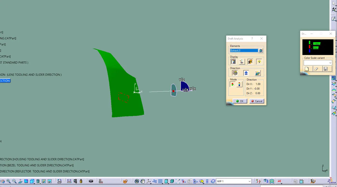
<!--[endif]-->
Creating the Reflectors for the lens:
- Designing the Reflector:
- A parabola is first designed for the backside of the reflector. The parabolic shape is chosen because it has the property of reflecting light rays in a way that they converge at a single focal point.
- A circular surface is created with the focal point of the parabola as the center. This circular surface represents the opening where the light bulbs will be placed.
- The parabola and the circular surface are then combined to achieve the desired shape and position of the reflector.
- Parameter and Relations Features:
- Parameter and relations features are used to specify the diameter of the parabola. These parameters can be modified in the future to adjust the reflector's shape according to the company's requirements.
- Placing the Bulbs:
- Once the reflector design is ready, bulbs are placed at the midpoint of the reflector, using the focal point where the parabolic shape and circular surface meet. The focal point helps direct the light from the bulbs to the desired area.
- Bulb Functions and Colors:
- Different types of bulbs are used for each function of the tail lamp, and their colors correspond to the specific functions:
- Tail/Stop Function: W21/5W Bulb (glows red when the vehicle stops or pauses in motion).
- Turn Function: W21W Bulb (activated when the driver uses the turn signal).
- Reverse Function: W16W Bulb (activated when the vehicle is in reverse).
- Importing Standard Parts:
- The bulbs and their holders, which are standard parts in the industry, are imported into the workspace for use in the tail lamp design.
- Positioning of Bulbs and Reflectors:
- The bulbs are positioned using the focal point, ensuring they align correctly with the reflector to achieve the desired light distribution.
- Industry standards are followed to determine the minimum and maximum distances at which each function's bulb should be placed. By adhering to these standards, the reflector's positioning meets industry requirements and ensures optimal performance of the tail lamp.
<!-- [if gte vml 1]>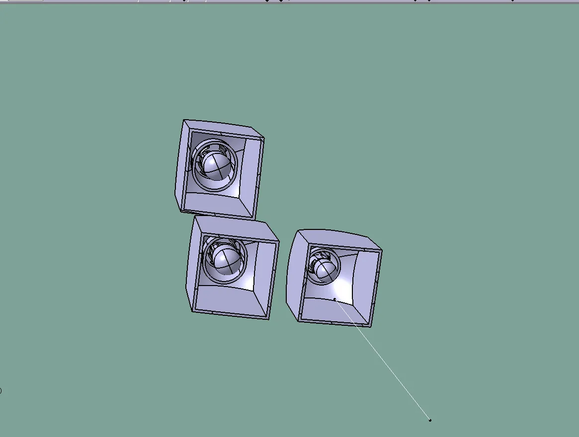
<!--[endif]-->
<!-- [if gte vml 1]>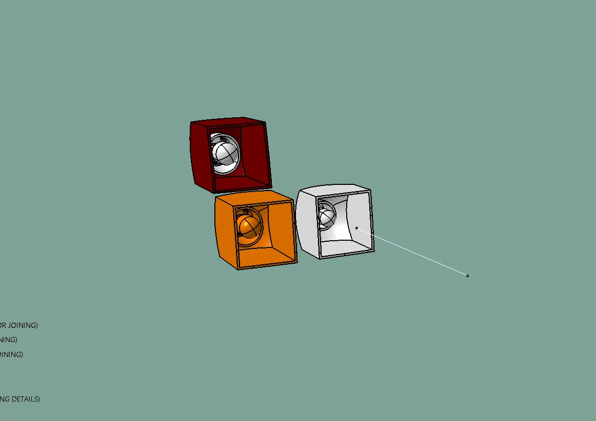
<!--[endif]-->
<!-- [if gte vml 1]>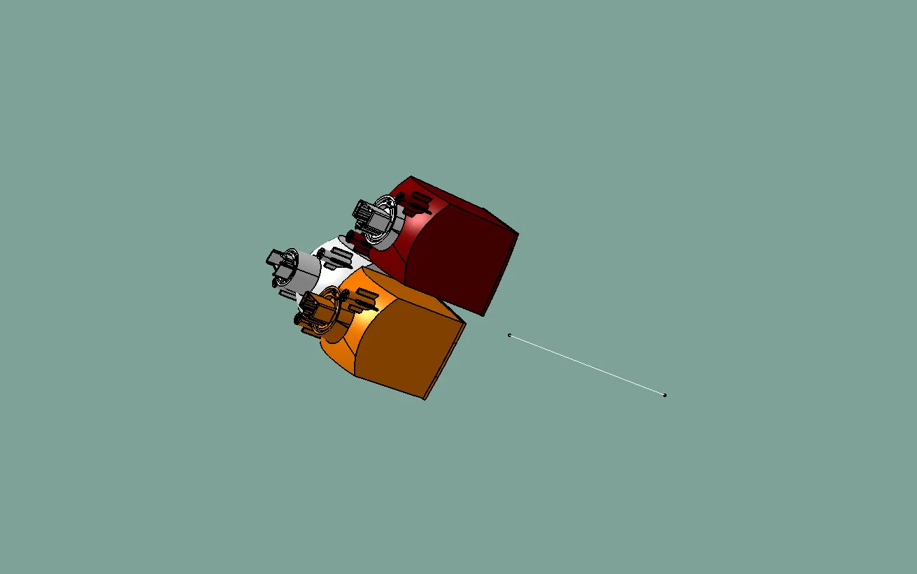
<!--[endif]-->
Creating the lens housing:
- Master Section Creation:
- A master section is created as a reference for designing the housing. This master section is derived from the surrounding features and welding tracks of the lens body's housing.
- Hot Plate Welding Technique:
- The lens body and the housing are attached using the hot plate welding technique. This method involves applying heat to the surfaces to be joined and then pressing them together to create a strong bond. The purpose is to ensure that the lens and housing are held together at the same meeting point.
- Preventing Light Bleeding:
- Light bleeding is a crucial consideration in housing design. It occurs when there are multiple reflectors in the housing, and the colors of light intersect, causing undesirable effects and reducing the clarity of the light output.
- To prevent light bleeding, the surrounding wall of the housing is maintained at a distance of 12-15mm from the lens. This distance allows for the successful execution of the hot plate welding operation without causing defects in the housing.
- However, in the middle section of the housing, a smaller distance of around 5-6mm is maintained. This is done intentionally to avoid light bleeding, ensuring that different colors of light do not intersect and compromise the desired light output.
- Light Bleeding Explanation:
- Light bleeding occurs when different colors of light emitted from different reflectors within the housing intersect with each other. When this happens, the clarity of the light is compromised, and the desired output is not achieved.
- By carefully designing the housing and maintaining appropriate distances between the lens and surrounding walls, the risk of light bleeding is minimized. The goal is to ensure that each color of light remains distinct and does not interfere with others.
<!-- [if gte vml 1]>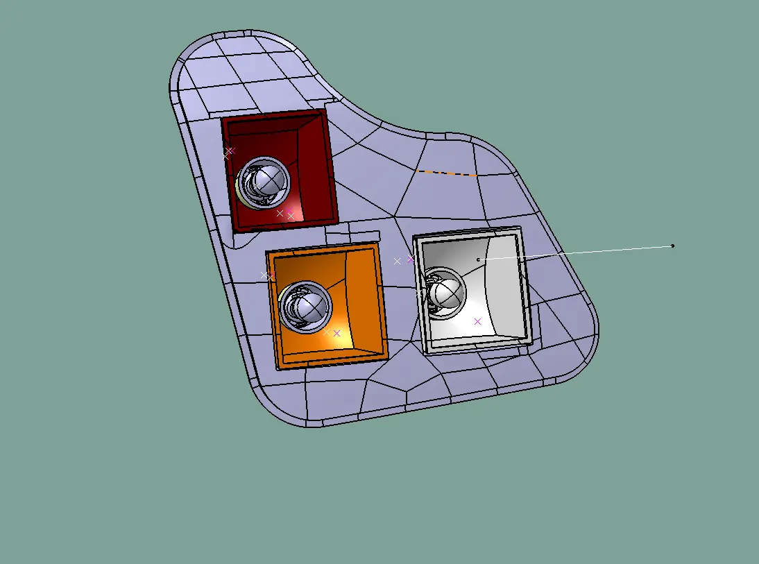
<!--[endif]-->
<!-- [if gte vml 1]>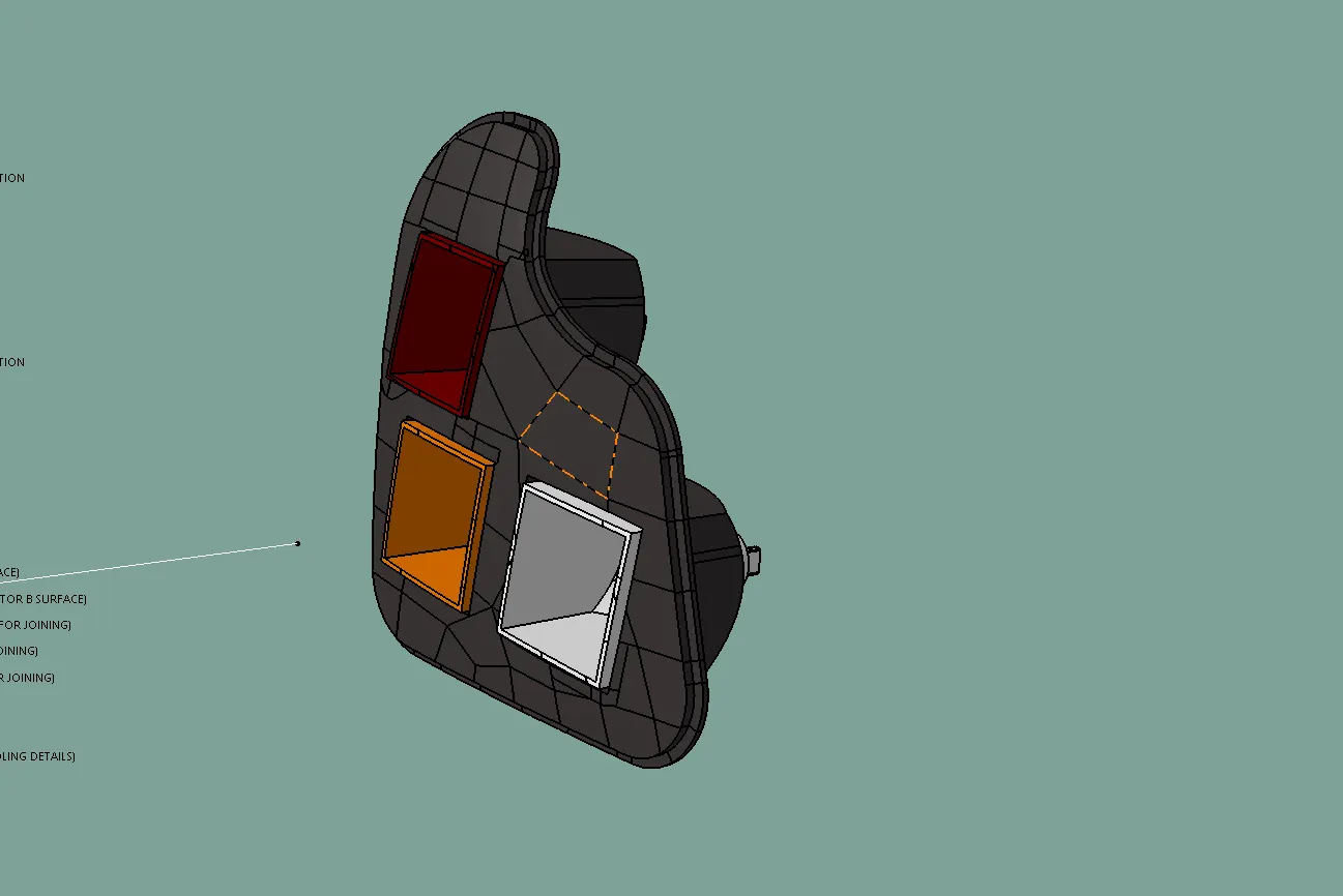
<!--[endif]-->
Crating the attachment features to the housing:
- Mounting Parts with Screw Bosses:
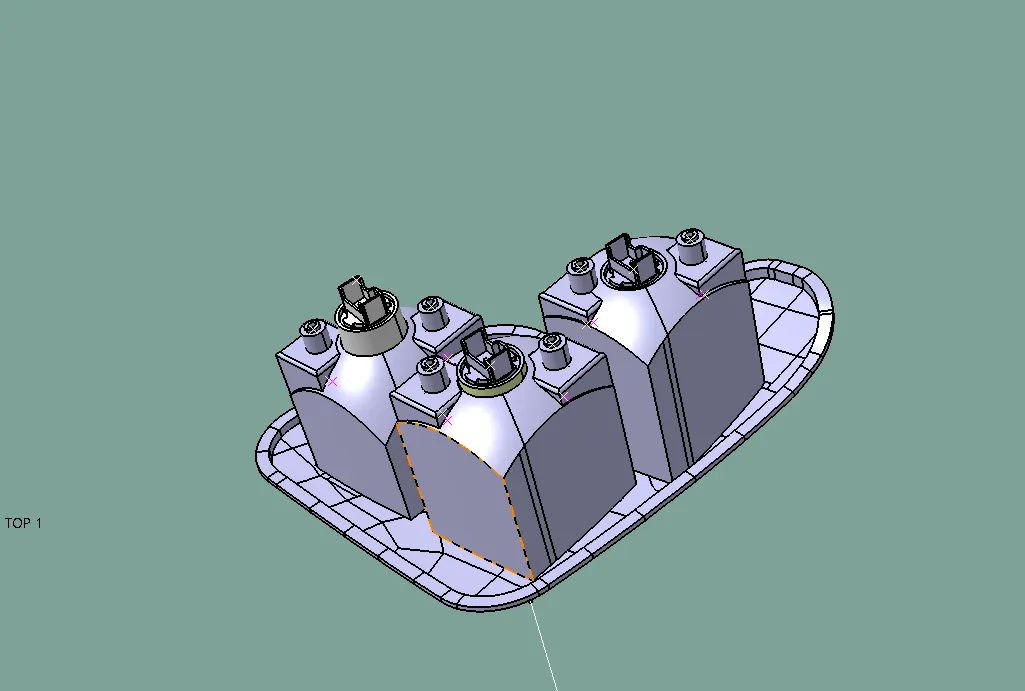
- Screw bosses are designed separately in a part called mounting parts. These screw bosses are raised structures with threaded holes where screws can be inserted and securely fastened.
- Once the screw bosses are designed, they are placed at appropriate positions on the housing to hold the reflectors in place.
- Union Trim with Housing:
- After designing the screw bosses, they are assembled with the reflectors to create the mounting parts.
- The mounting parts are then union trimmed with the housing. Union trimming is a process of combining separate parts together to create a single integrated design.
- Use of M4 Screws:
- M4 screws are chosen as an industry standard for fastening the lens with the housing. These screws are commonly used in automotive applications due to their size and strength.
- Placement on Dog Houses:
- The screw bosses are placed on the dog houses, which are specific areas on the housing designed to accommodate the screw bosses. By placing the screw bosses on the dog houses, sink marks or defects on the solid body during the molding process are avoided.
- Studs for BIW Attachment:
- Studs are placed on the top of the screw bosses in the dog houses. These studs serve as attachment points for securing the lens and housing with the Body in White (BIW) structure of the vehicle. BIW refers to the main structural body of the vehicle before the addition of outer panels.
- Designing of Dog House for Tooling Ease:
- When designing the dog houses, consideration is given to ensure that they are clear along the lifter tooling direction. Lifter tooling refers to the components used in the mold to create undercuts or features that require the mold to move in a specific direction for easy removal of the molded part.
- Designing the dog houses with clear lifter tooling directions allows for easier tooling and mold release during the manufacturing process.
<!-- [if gte vml 1]>
<!--[endif]-->
<!-- [if gte vml 1]>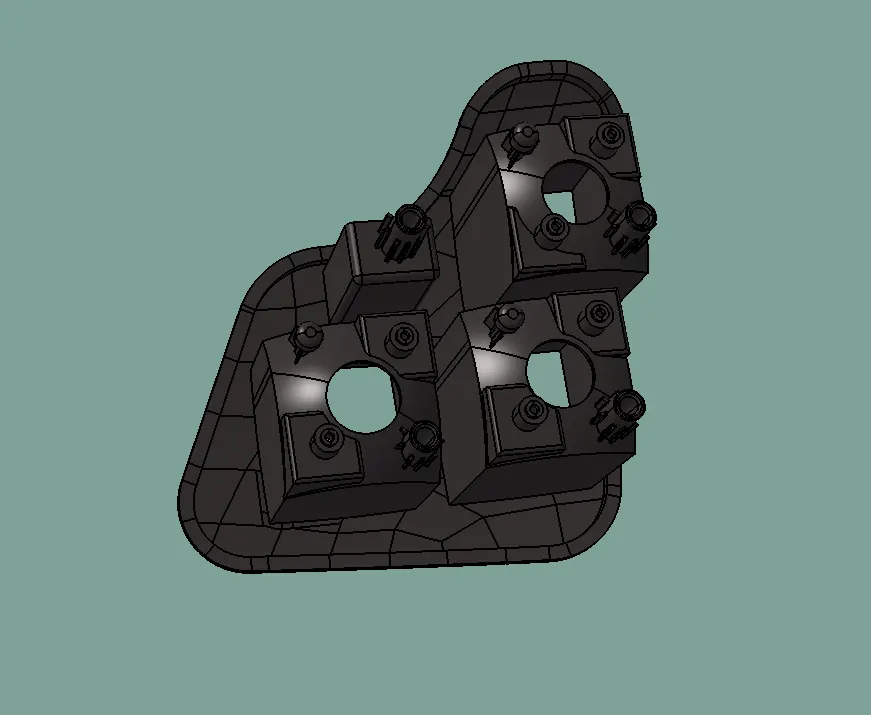
<!--[endif]-->
Creating vents caps and hole:
Preventing condensation inside the lens is a critical consideration in the design of automotive tail lamps. Condensation occurs when there is a temperature difference between the inside and outside of the lens. This temperature difference can cause moisture to accumulate on the inner surface of the lens, leading to unclear visibility and potentially affecting the performance of the light.
To address this issue, vents are strategically placed in the reflectors to allow the heat generated by the bulbs to escape easily from the back side of the reflector. These vents serve as pathways for air circulation, helping to equalize the temperature inside and outside the lens. By maintaining a consistent temperature, the risk of condensation is reduced.
The positioning of the vents is also carefully considered to meet several criteria:
- Invisibility to the Customer: Vents are placed in areas that are not easily visible to the customer from the outside of the tail lamp assembly. This ensures that the overall appearance of the tail lamp remains aesthetically pleasing.
- Functionality: The vents are designed to efficiently perform their function of allowing heat and moisture to escape. Their size, shape, and placement are optimized to achieve this goal effectively.
- Unobstructed Light: The placement of vents is carefully planned to avoid obstructing the flow of light or light reflection within the lens. Ensuring that the vents do not interfere with the light path ensures that the tail lamp provides the desired illumination and visibility.
By considering these factors, designers can create a tail lamp design that effectively prevents condensation, ensures optimal light performance, and maintains a clear lens for safe and reliable operation. Proper venting is essential for maintaining the quality and longevity of the tail lamp in various weather conditions and temperature fluctuations.
<!-- [if gte vml 1]>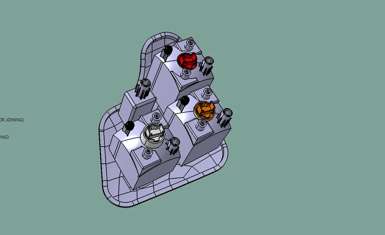
<!--[endif]-->
<!-- [if gte vml 1]>
<!--[endif]-->
Creating of Wiring Harness:
Creating a wiring harness for the tail lamp is an essential part of the overall electrical system in a vehicle. The wiring harness consists of electrical cables or wires bound together to transmit signals and electrical power for various functions of the tail lamp. Here's a breakdown of the process:
- Function and Color of Wires:
- Each function of the tail lamp is assigned specific colored wires for easy identification and proper connections. The functions and their corresponding wire colors are as follows:
- Tail/Stop Function: 1 Brown wire for Tail Function, 1 Red wire for Stop Function.
- Turn Function: 1 Orange wire for Turn Function, 1 Black wire for Ground.
- Reverse Function: 1 White wire for Reverse Function, 1 Black wire for Ground.
- 4-Pole Connector:
- The wiring harness is designed to connect with a 4-pole connector. This connector provides all the necessary wires for the various functions of the tail lamp. It simplifies the installation process by combining multiple wires into a single connector.
- Grommet for Connector:
- A grommet is designed at the backside of the housing to serve as a connector between the 4-pole connector and the wires coming out from the housing. The grommet acts as a protective seal, preventing moisture and dust from entering the tail lamp assembly and ensuring a secure connection between the wires and the connector.
- Additional Wire Integration:
- At the grommet location, additional wires can also be fixed to provide more functions to the tail lamp. These additional wires can be used to accommodate extra lighting or other electrical components, expanding the capabilities of the tail lamp assembly.
<!-- [if gte vml 1]>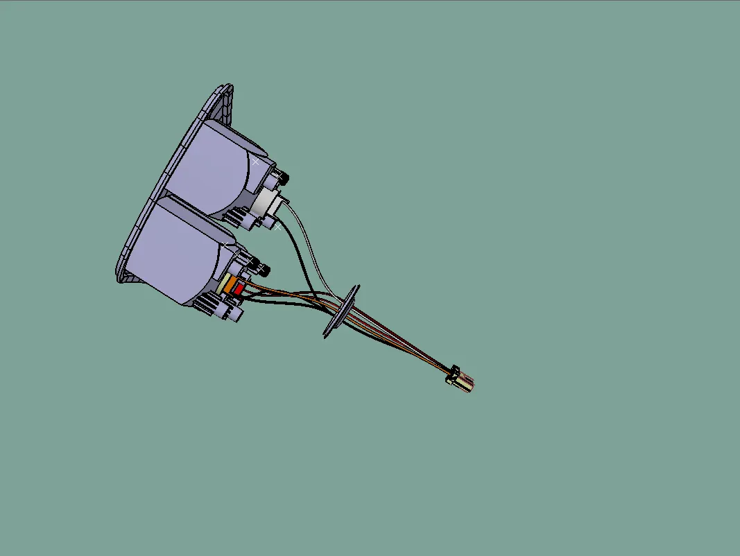
<!--[endif]-->
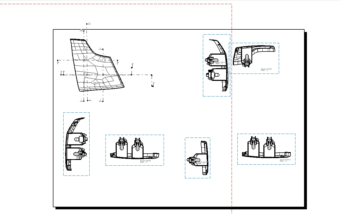
Part drawing for the tailamp
<!-- [if gte vml 1]>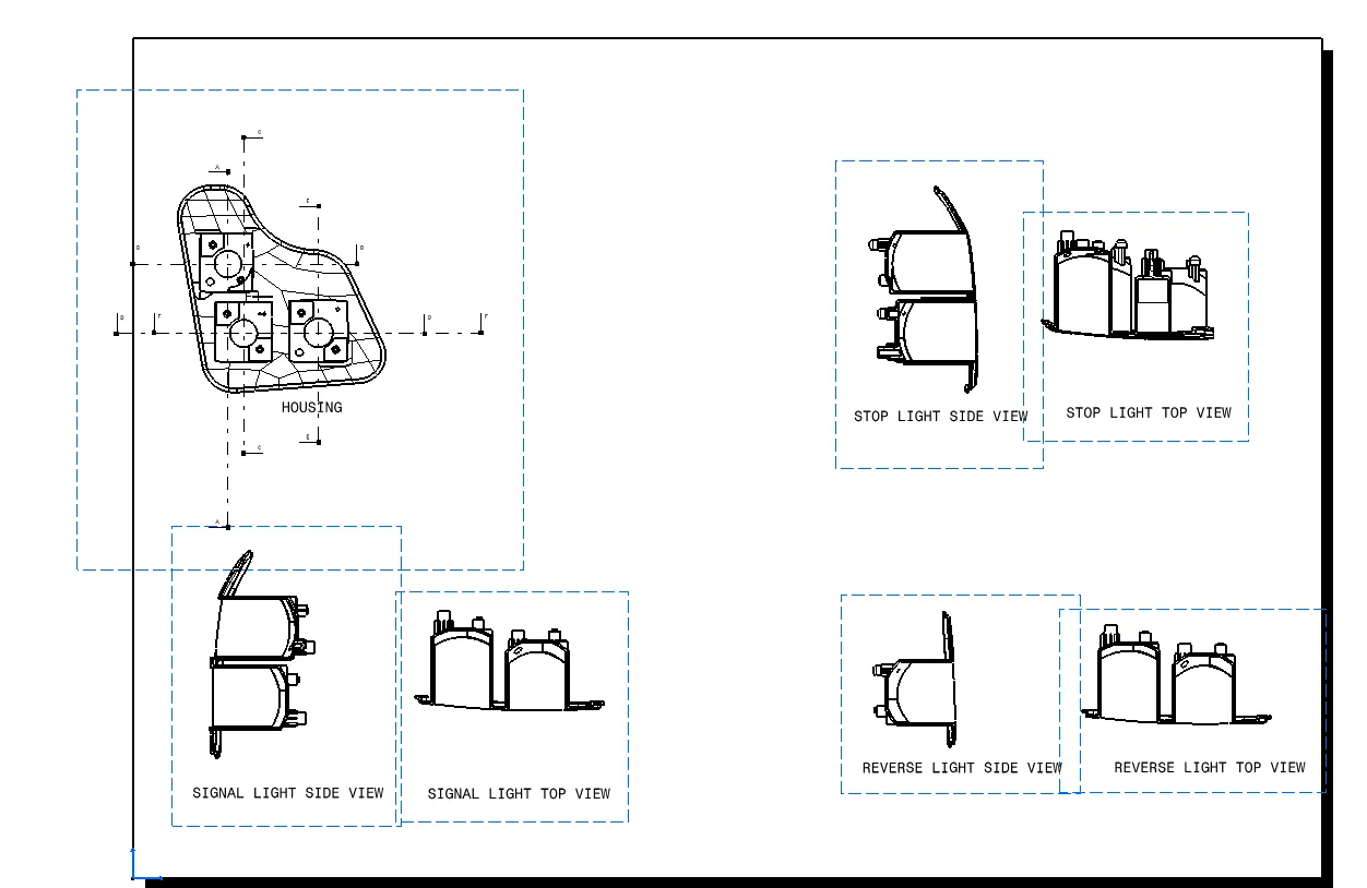
<!--[endif]-->