Bumper Design
BUMPER DESIGN
AIM
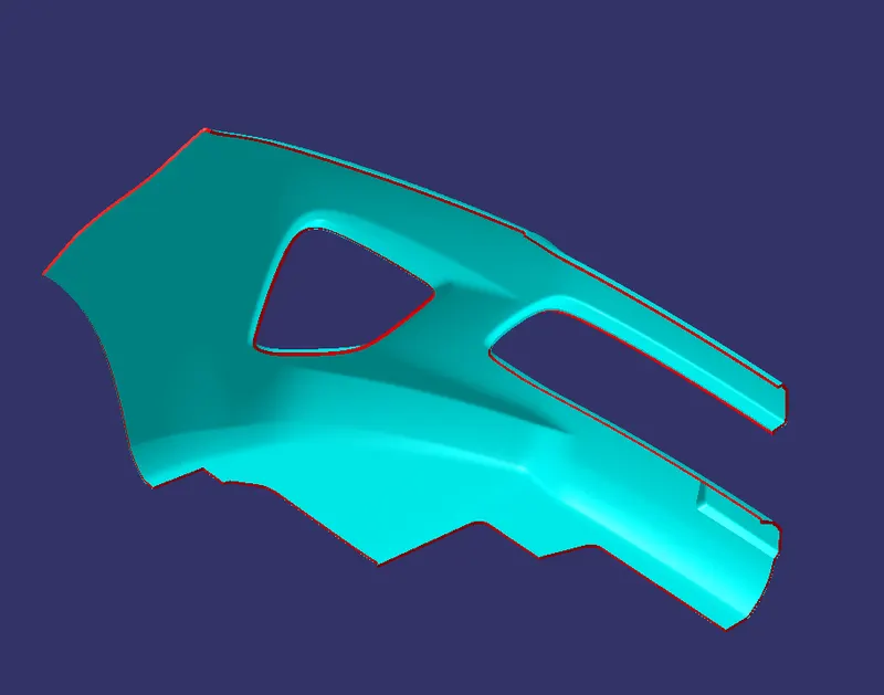
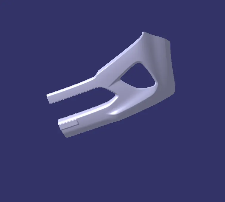
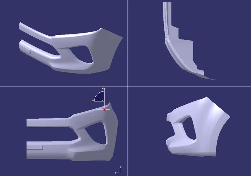
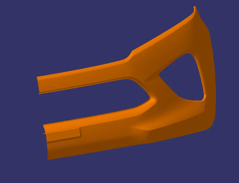
Create the Bumper Plastic component through the given Class-A surface. To begin with, the tooling axis for the given Class-A Surface should be created meeting the requirements of the draft angle and at the end perform the Draft analysis on the model.
INTRODUCTION
A car bumper is a vital component of an automobile's exterior, serving as a protective barrier between the vehicle's body and potential impacts. It is typically located at the front and rear ends of a car, although some vehicles may have additional bumpers on the sides. The primary purpose of a car bumper is to absorb and distribute the force of a collision, minimizing damage to the vehicle and its occupants.
Historically, car bumpers were made of heavy metal materials, such as steel, designed to withstand impacts and provide robust protection. However, modern bumpers have evolved significantly, incorporating advanced engineering and materials to enhance their functionality and aesthetics.
Today, car bumpers are commonly composed of a combination of plastic, fiberglass, and other lightweight materials, which provide both durability and flexibility. This composition allows the bumper to absorb impact energy and return to its original shape after a minor collision, reducing the risk of permanent deformation or damage to the vehicle's body.
In addition to their protective role, car bumpers also contribute to the overall design and aesthetics of a vehicle. Automakers often customize bumper designs to align with the vehicle's style, integrating them seamlessly with the body panels. Bumpers may feature aerodynamic elements, stylish contours, and integrated fog lights or sensors for various driver-assist systems.
Furthermore, car bumpers can house additional components such as parking sensors, cameras, or adaptive cruise control radar systems. These advanced technologies enhance driver safety and convenience, while the bumper ensures their protection and optimal functionality.
Overall, the car bumper plays a crucial role in protecting the vehicle and its occupants during collisions, absorbing impact energy, and minimizing damage. Through innovative materials and design, modern bumpers strike a balance between strength, flexibility, and aesthetic appeal, contributing to both the functionality and visual appeal of today's automobiles.
TOOL AXIS
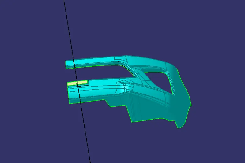
For this model direct method is used
- Extract the flat surface
- Create a point at centre of the surface
- Then Create a line at the point in X direction
DRAFT ANALYSIS
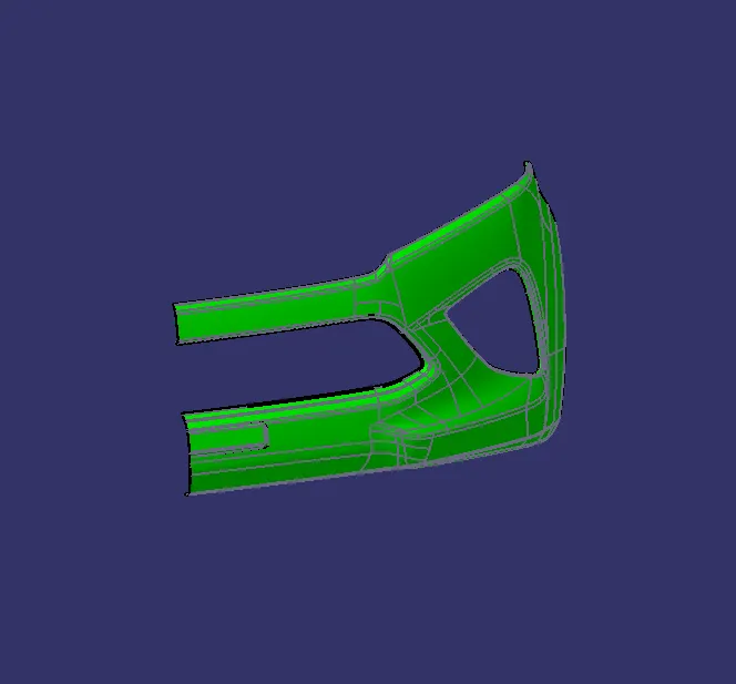
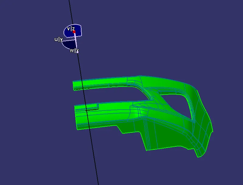
- The Draft analysis is performed on the Class A surface
- By using the feature draft analysis command
- Using this command the compass was set on the tooling axis
- If its green then is move to B Surface creating
CREATING OF CLASS B SURFACE
-
Aesthetics: Class B surfaces are expected to have a high level of visual quality. They should be free from visible defects, such as sink marks, scratches, waviness, or inconsistent reflections, that could detract from the overall appearance of the vehicle.
-
Smoothness: Class B surfaces should exhibit a smooth and uniform finish. They are often required to have a high-gloss or low-gloss appearance, depending on the specific design requirements.
-
Symmetry: Class B surfaces are designed to be symmetrical and visually balanced. This symmetry contributes to the overall harmony and coherence of the vehicle's design.
-
Tolerance control: Class B surfaces require precise control of tolerances to ensure that all components fit together accurately. This includes dimensional tolerances, gap and flushness tolerances, and alignment with other parts of the vehicle.
-
Design complexity: Class B surfaces often feature complex curves, contours, and transitions. These design elements add to the visual appeal of the vehicle but also pose challenges in terms of manufacturing, tooling, and maintaining the desired surface quality.
-
Tooling and manufacturing considerations: Achieving Class B surfaces requires advanced manufacturing techniques, such as injection molding, thermoforming, or other plastic forming processes. Special attention must be given to tooling design, surface finish, mold temperature control, and material selection to ensure the desired surface quality is achieved.
Steps
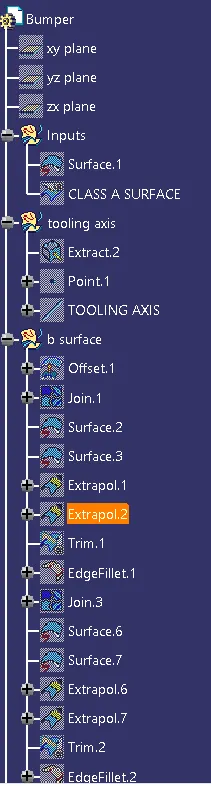
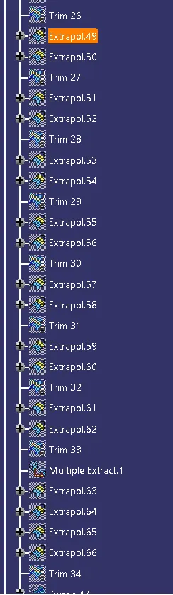
- In this model first Offset the class A surface at 3 mm
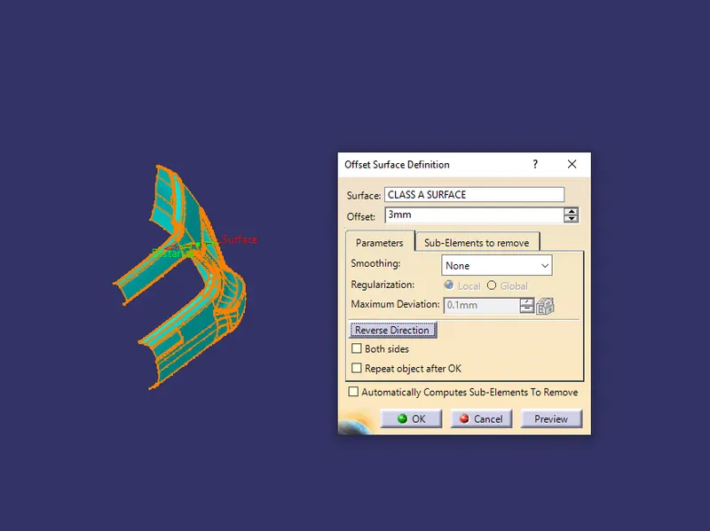
- Now there is some gap at fillet area
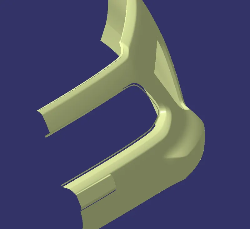
- Recreate this surface
- Then fillet that surface
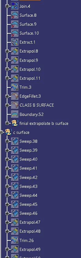
- Then extrapolate the egdes of the Class B surface
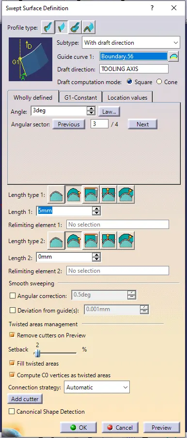
CREATING CLASS C SURFACE
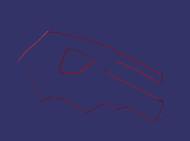
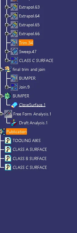
Then Join and Trim A B C surface