Door Trim Lower with Engineering Features
AIM
Create the Door trim lower plastic component through the given Class A surface. Also to create heat stakes and locators considering all the design rules.
OBJECTIVE
- Create Tooling axis for the given Class A surface.
- Create the Class B and Class C surface of the door trim using the given Class A surface.
- Create final surface model and convert it into soild body using close surface command in the part design workbench.
- Create Heat stakes and locators on the B surface of the door trim part body
- Perform draft analysis for Class A surface and final part body
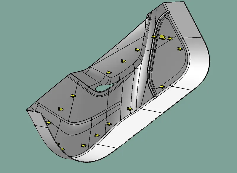
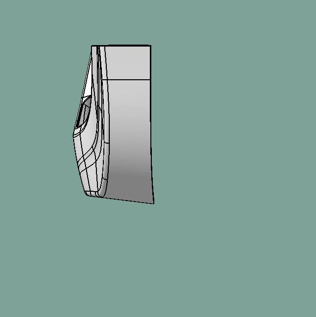
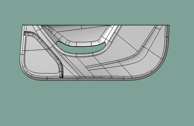
Given Class A surface
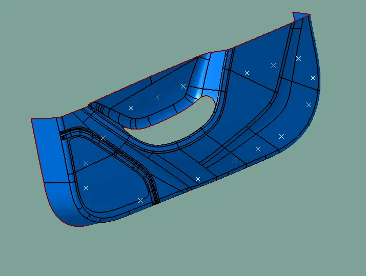
Check for continuity of the given surface using join or boundary commands.
If there are no gaps on the A surafce create tooling axis
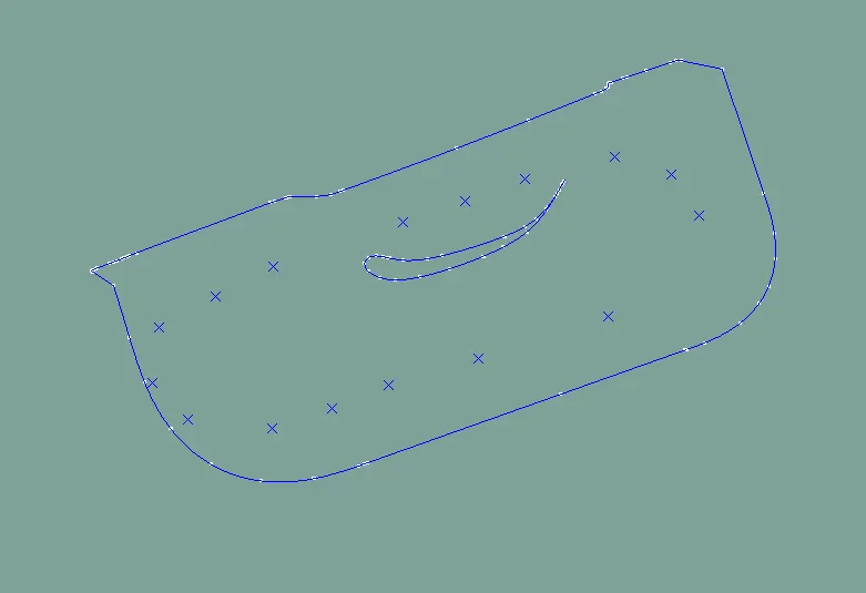
Tooling axis creation
- Now extract any surface and create a mid point on it
- Since all the face of the given surface have draft angle more than 3 degress
- In this model I chosen the normal to the surface methods to create the tooling axis .
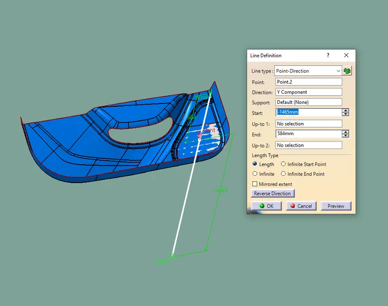
That white line is tooling axis
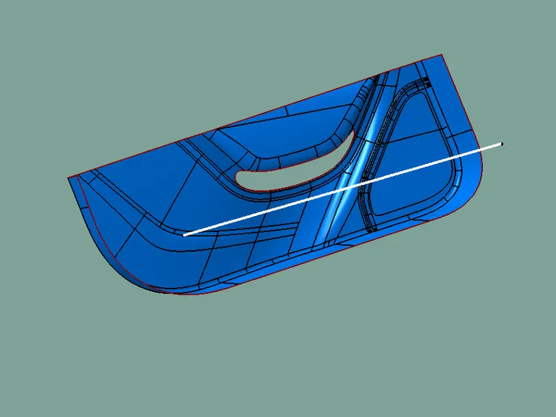
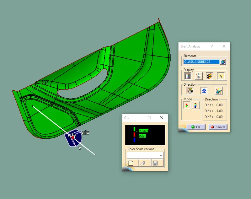
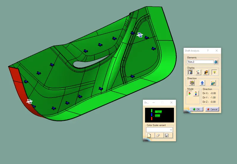
Draft Analysis Of Class A Surface
Class B Surface Creation
Class b surface means thickness of a part it is not visiable and is inside part . This is the surface that contains engineering aspects of a model
- Create offset Surface of the Class A at 2.5 mm inwards direction.
- Check for the discontinuity and rework on the offset surface using extact multi extact multi section surface.
- Join the surfaces and ensure the finail Class b surface created has no gaps.
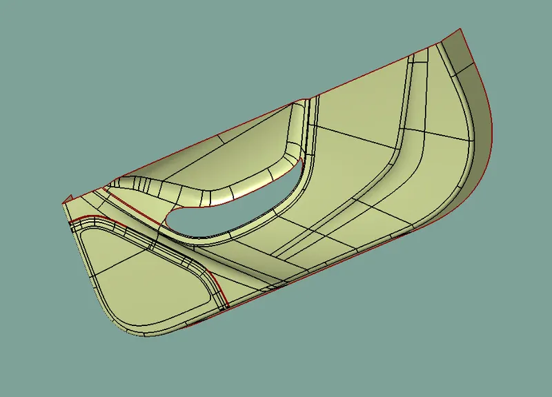
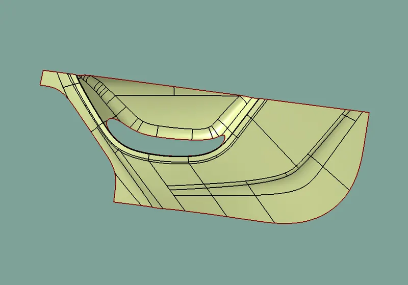
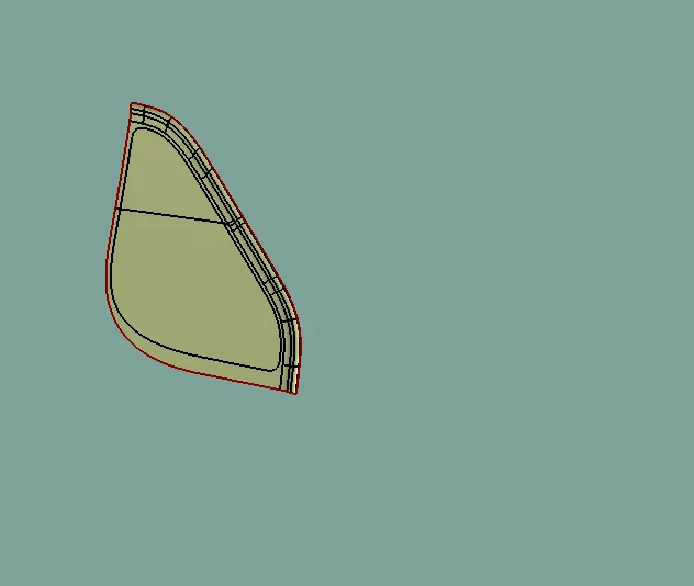
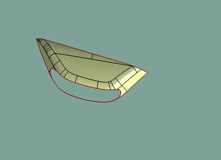
Final CLASS B Surface
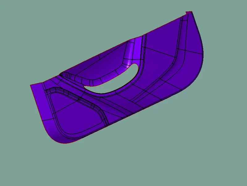
Class C Surface creation
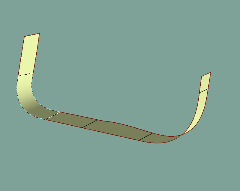
Surface that joins class A and class B Surface is class C Surface . Class c is often specified for interior surface not readliy visible surface that will be covered by another part when assembled
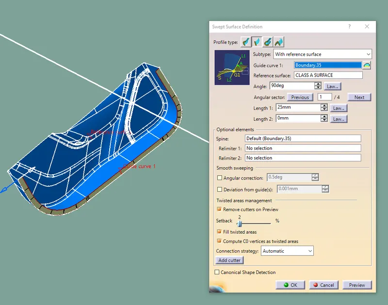
- Create the sweep syrface with reference to surface and tooling bymulti extracting the Class A boundary
- Join the sweep surface by commands like extrapolate, trim
- finally join all the sweep surface and ensure the continuity of the Class c surface.

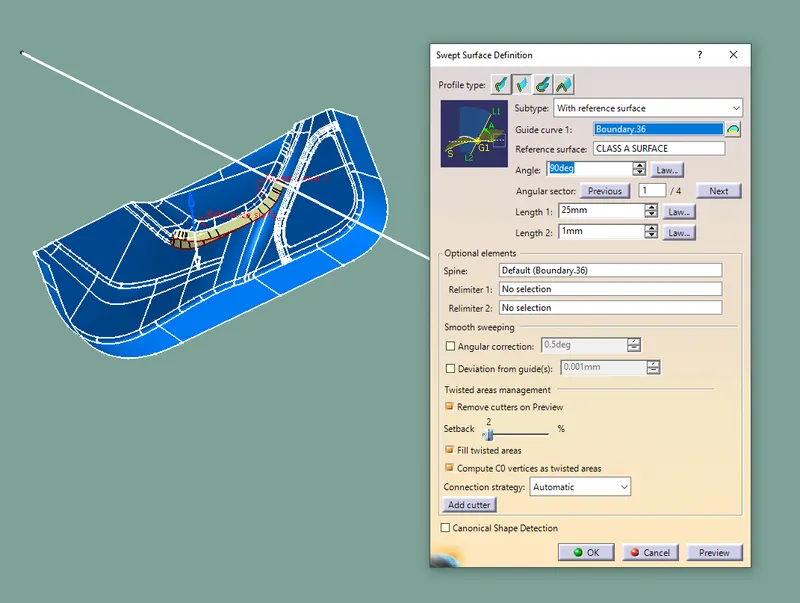

Creating The final Surface
- For creating the finals door trim surface, join the Class A and class c surface together
- Then trim the class B Surface with joined surface (class A and C)
- Ensure the final surface has no gaps using the boundary command
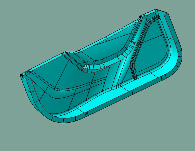
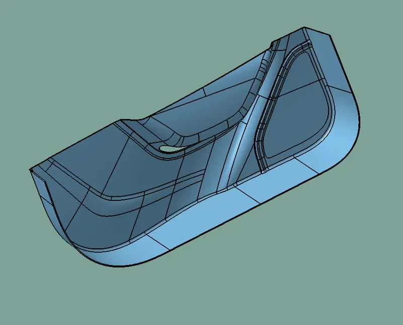
Close Surface
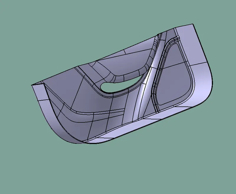
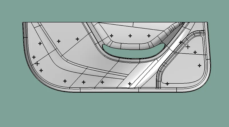
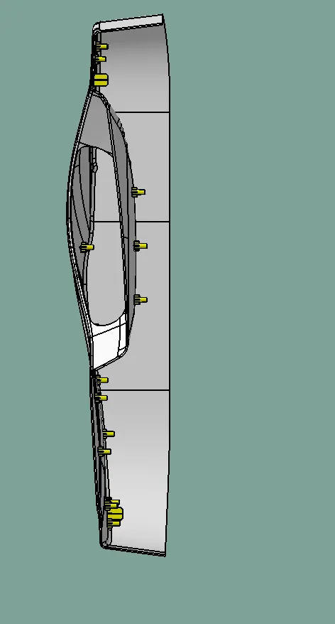
Creating engineering features on the B surface
Locators creation
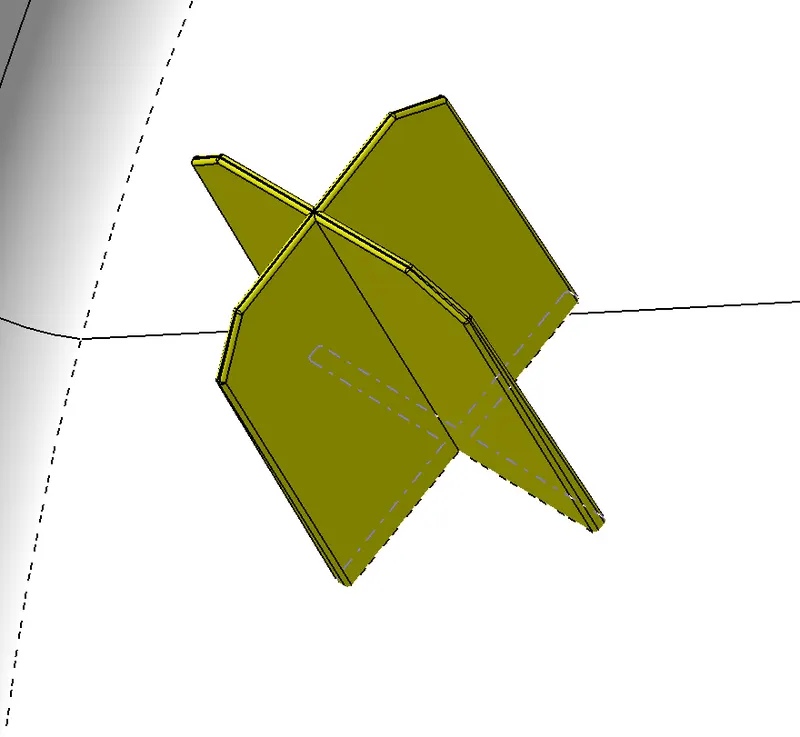
Locators are used when assembling sub parts and very useful engineering feature for east way of locator for the given door trim design
Type of locators
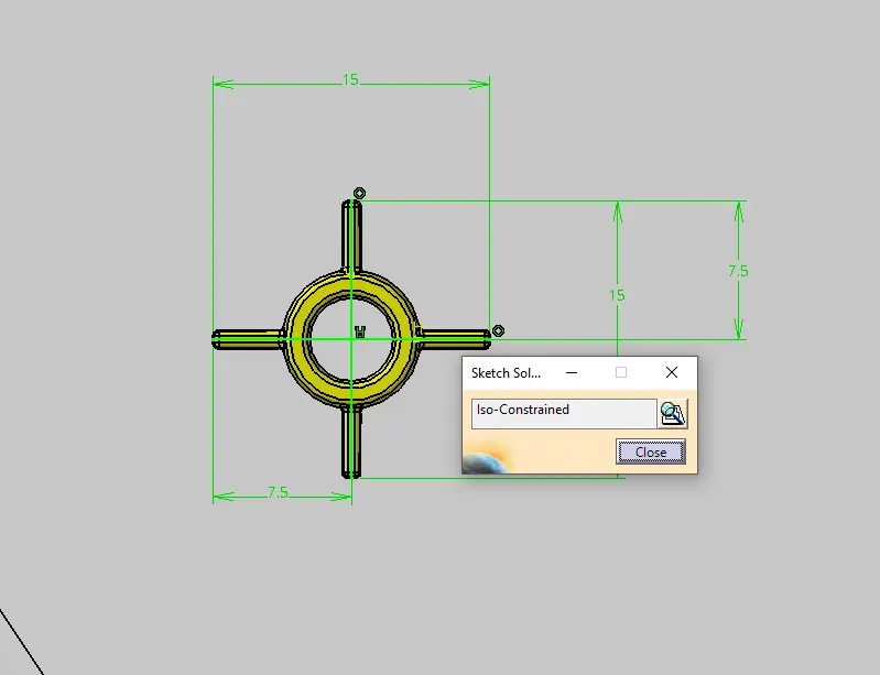
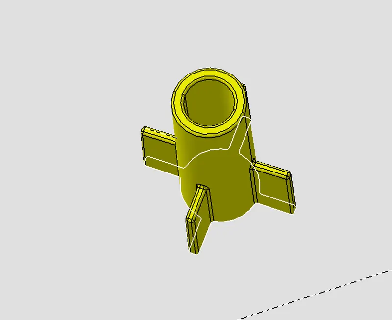
- 4 way locator
- 2 way locator
Design procedure
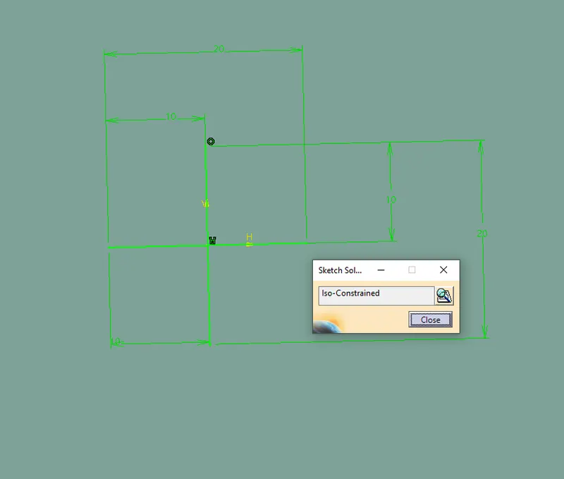
- Create position sketch and make requied iso constrained sketch.
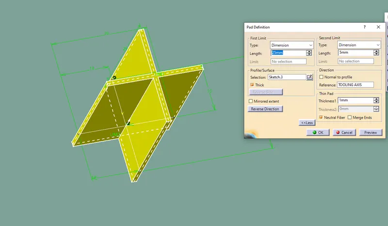
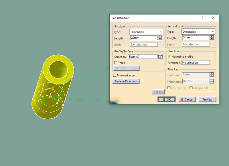
- Pad the sketch profile with reference to the tooling axis.
- Locators height should be more than that of heat stakes.
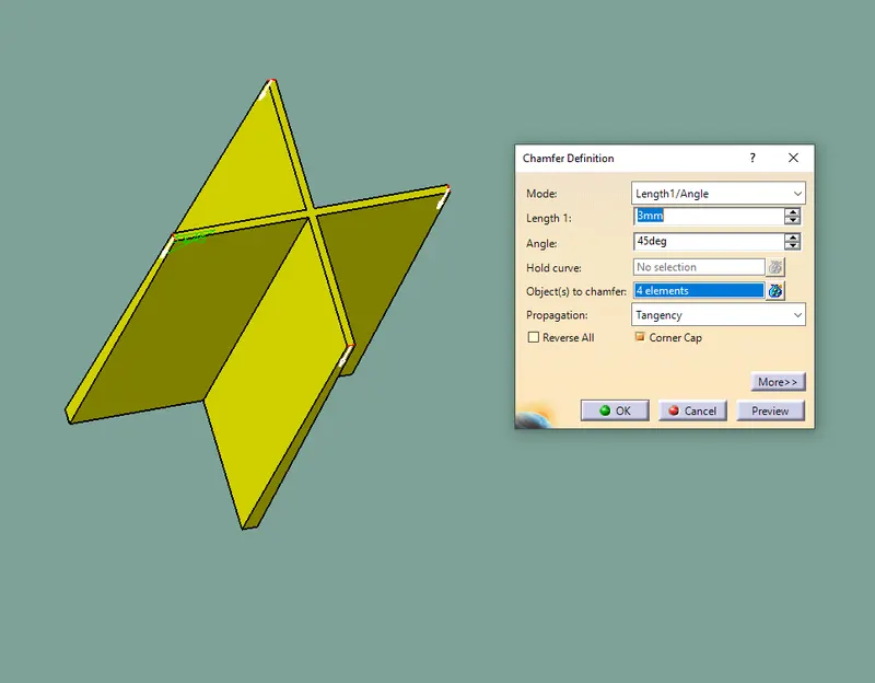
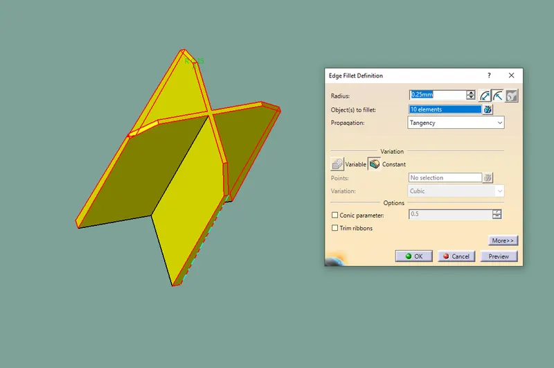
- Create chamfer of 45 degree with 3mm
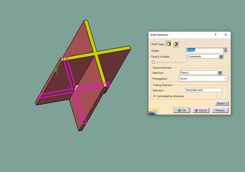
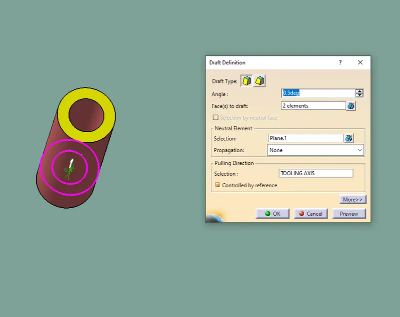
- Draft angle 0.5 degree to all faces
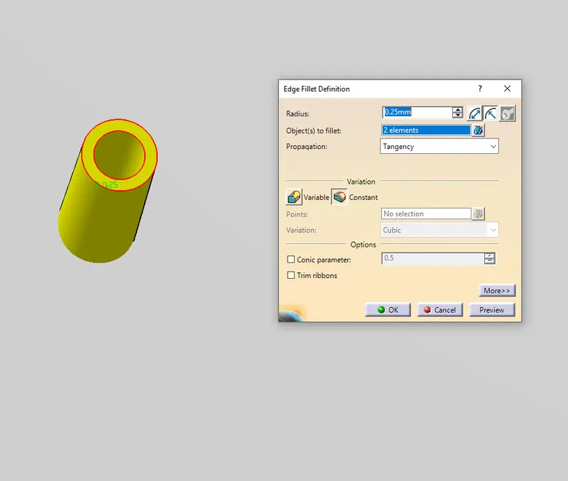
- Edge fillets 0.25mm to all edges
- By used translation command to we can move by copy complete locators
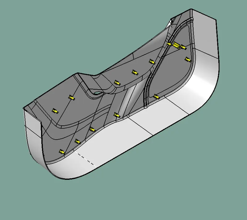
- Finally using union trim Boolean operation, trim the locators with the door trim body part
Heat Stake
Heat staking is a process used to join two or more plastic parts together without using any additional materials like adhesives or fasteners . In this process heat is applied to a specific area of a plastic part softening it to a molten state and then joining it to another part.
Heat Stake Design Procedure
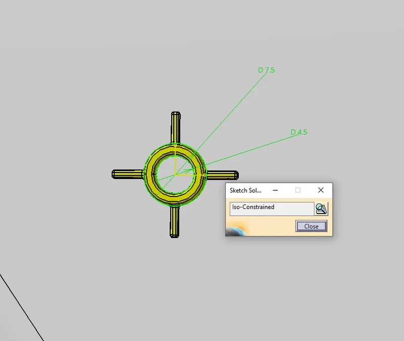
- Using position sketch create sketch of the heat stake profile
- Pad it with reference to the tooling axis
- Heat stake height should be lesser than the height of locators provided.
- Thickness should be 40 %of the component main thickness to avoid sink marks on the A surface.
- Provide draft angle of 0.5 degree on both inside and outside walls of the heat stake
- There should be minimum 50mm gaps between each heat stakes
- create more heat stakes by special copying option and translate it to desired points
- Then union trin them with door trim part body to get the final component
Draft Analysis
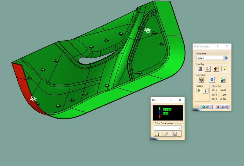
Draft Analysis is done after determining the tooling axis ,draft analysis is used to check whether the minimum draft 3degree is maintain or nott
Procedure of Draft Analysis
- Changethe view mode to materials
- Then open the draft analysis command
- Then click on use the compass to define the current drafting direction and then drag and align the compass on the tooling axis
- Then lock the compass and perform draft analysis by clicking on the component
Colour represention
Green - Positive draft
Blue - Zero draft
Red - Negative
- Draft analysis with 2.9 degress value
- Draft Analysis with 0.45 degree
Conclusion
I have created class B and c surface using the given class A surface and created engineering features om class B surface.Draft analysis is successfully performed on both Class A surface and Final component.