Wiring harness routing & packaging Rules

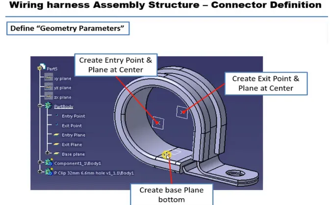
PROCESS
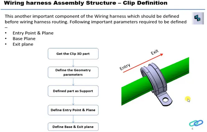
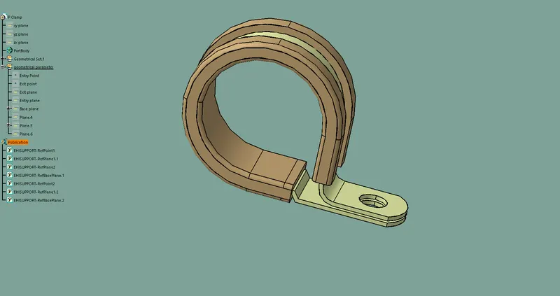
- Download the cad file of P clamp from given link
- Upload the cad file in catia v5 part design workbench
- Create two point on both entry and exit center side of the P clamp
- Create 3 planes on the P clamp at center of entry plane , center of exit plane and bottom base plane
- Now open electric part design
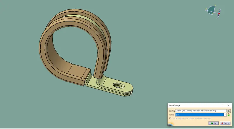
- Click on define support part command
- Here select part,-select exit point-select exit plane -base plane
- Again Open same command and again selecet part-select exit point-and base plane as secondary palne are selected automatically
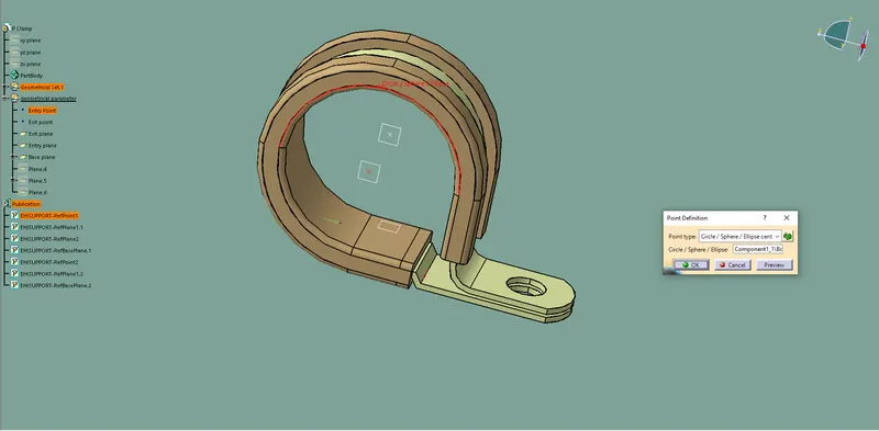
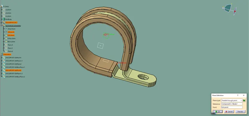
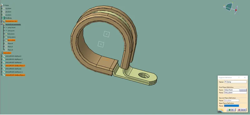

STEP BY STEP
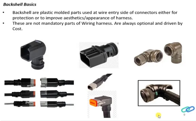
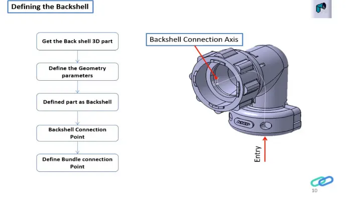
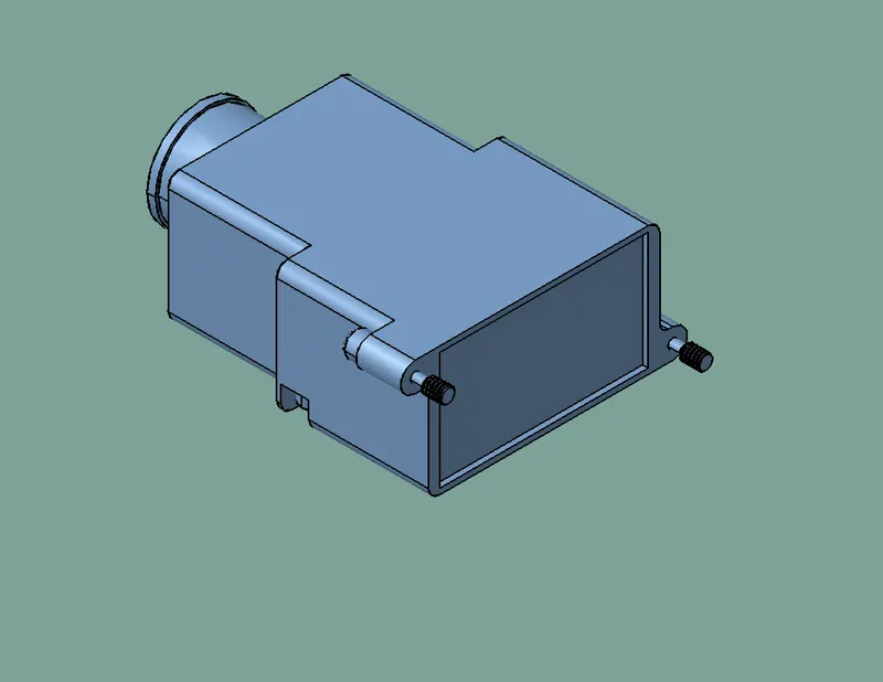
- Download the back shell cad file from given link and open it on catia v5 in part design workbench
- Identify which side is connector mating and which side is the bundle entry
- Create mid point in both at connector matiing side and bundle entry side
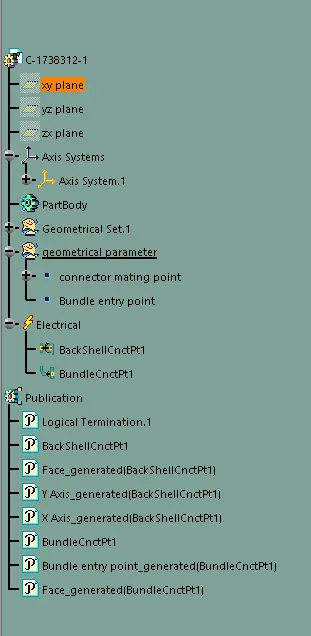
- Now create a axis system in connector mating side point
- Here Yaxis is in mating direction, Xaxis is in locking side
- Switch to electrical part design workbench
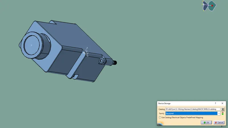
- Click on define back shell command and select the part now it is defined as the back shell
- Then click on the define back shell connection point and fill the table as show in fig 3
- Do Same in as define bundle connection point.fig 4
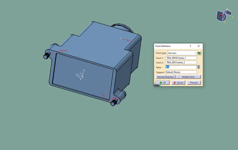
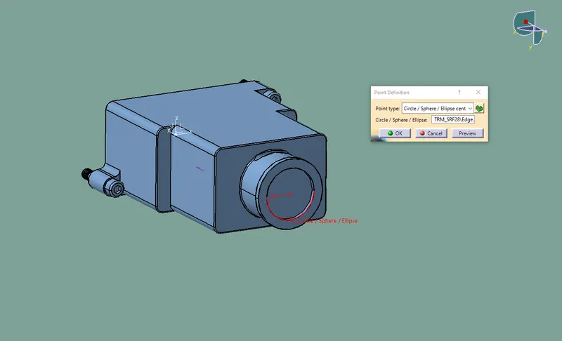
fig 3
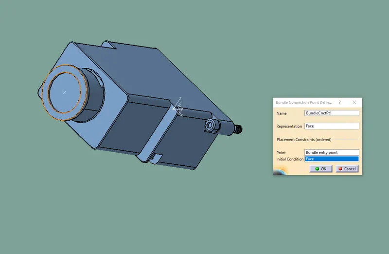
fig 4
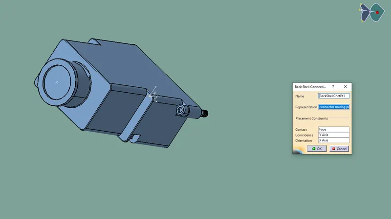
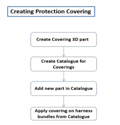
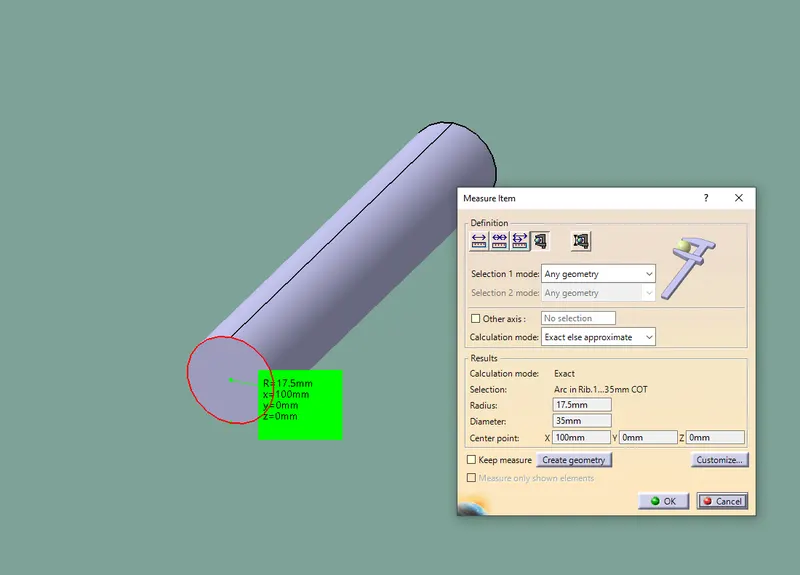
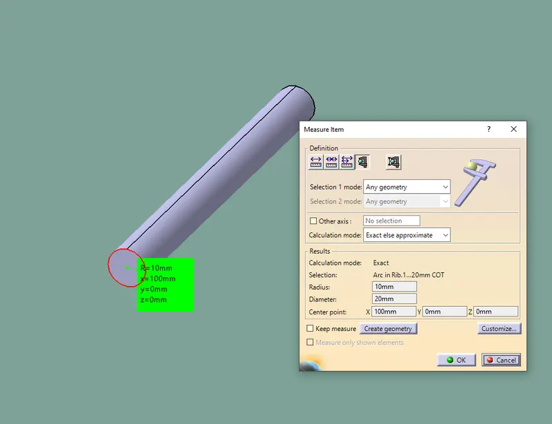
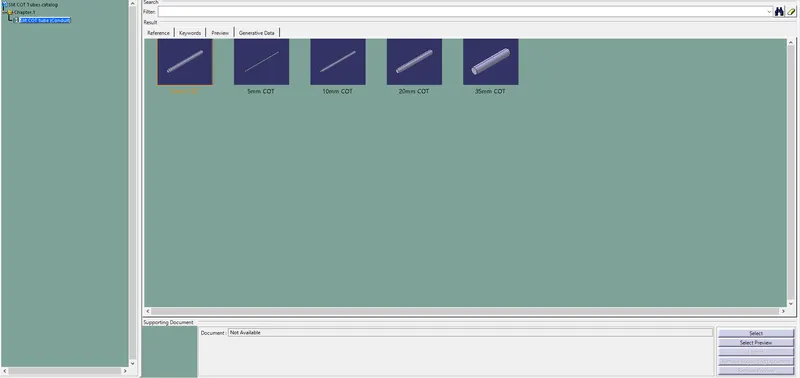
Creation of catalog
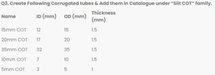
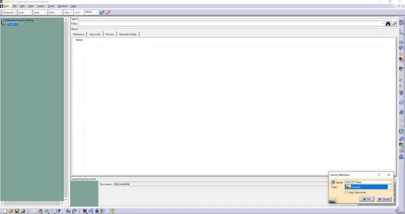
Create a catalog doc and named it as Slit COT Tubes as shown in below fig and saved it
Creation of Protective Covering
- Switch to electrical part design
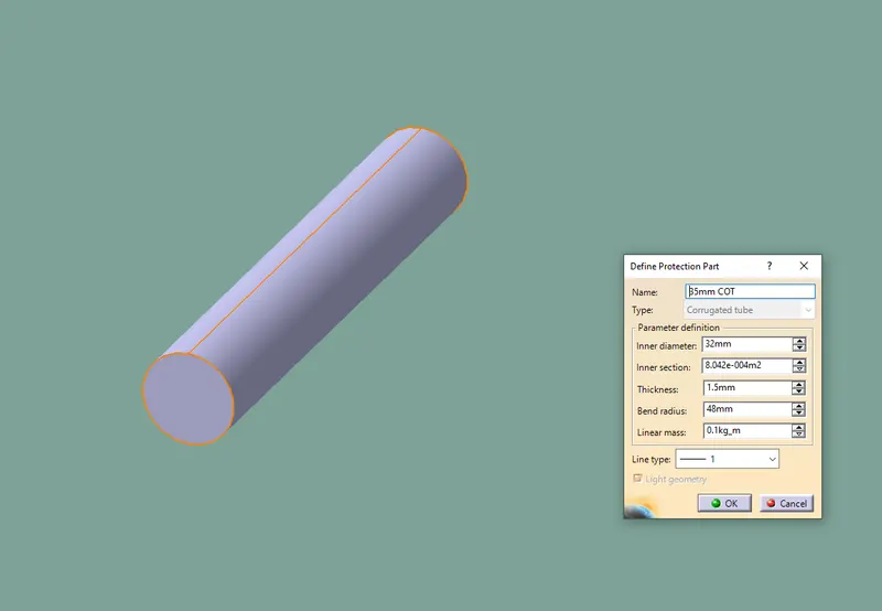
- Click on the define protection part command
- Then click on the part in tree specification
- Then a tab is open fill it by required diamension bend radius is 1.5x outer diameter