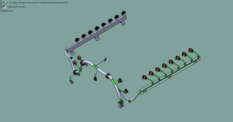
Route the wiring harness and prepare flatten view drawing in CATIA V5
AIM :
To route the wiring harness on given engine and prepare flatten view drawing in CATIA V5 .Application of all packaging rules and industry best practices .Apply protection coverings as required.
INTRODUCTION OF WIRING HARNEESS:
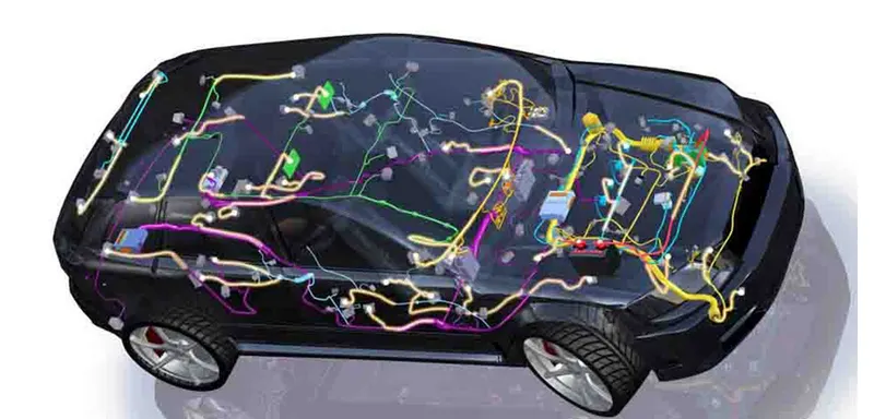
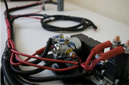
It is a collection of wires bundled together and enclosed within a protective sheath or casing. it provides a systematic and organized approach to routing snd connecting electrical components in various system, such as automotive aerospace and other industrial applications .The protective sheatgh help safeguard the wire from abrasion, moisture, heat, and other envirimental factors, ensuring reliable and efficient operation off the electrical system .Wiring harness are essential for ensuring proper connectivity, minimizing the risk of electrical short or faults , and simplifying installing and maintence processes
OBJECTIVE:
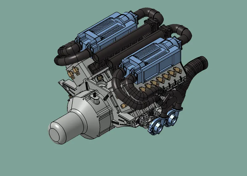
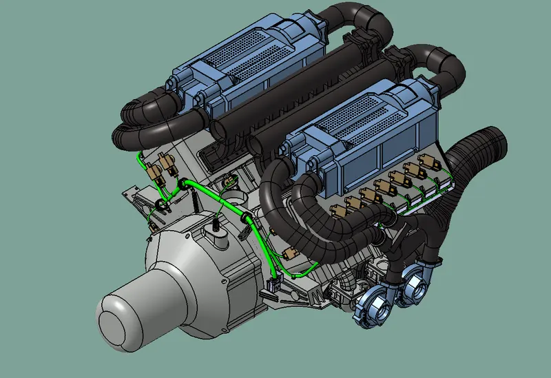
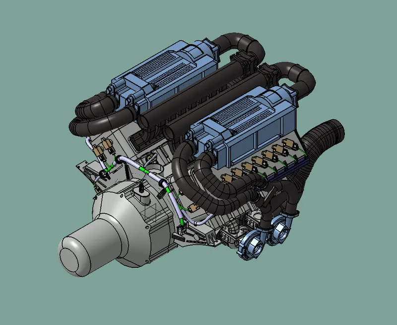
- The given engine was has 16 fuel injectors 8 are palced in left side and other 8 are placed in right of the engine block, they are connected by a 4 pole connector with the wiring harness
- Engine Coolant sensors at the centre off the engine between the two blocks which is connected by a 2 pole connector with the wiring harness
- Other 2 poles connector are in engine one sensor is to measure vehicle speed and other is to sense neutral position of the transmission assembly which are connected with wiring harness
- Two Camshaft sensors on each engine block (4 camshaft sensors), which are connected by a 4 pole connector with wiring harness
- An interconnection connector to connect engine harness system to vehicle harness system
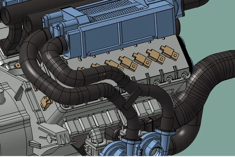
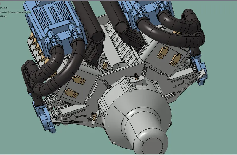
Designing a wiring hareness for a V16 Engine in CATIA V5 involves several steps and considerations here is an outline of the process,including the necessary detials and industry best practices to follow:
- Gather information :
- Obtain the V16 engine specifications, including dimensions, mounting points and any specific requirements for the wiring harness.
- Identifty the electrical components that need to be connected by the harness
- Review any relevant industry standards or guideliness for wiring harness design
2. Create a harness Routing Plan:
- Analyze the engine layout and identify suitable paths for routing the wiring harness
- Consider packaging rules such as minimizing wire lengths, avoiding sharp bends, and ensuring proper clearance from heat sources, moving part and other components
- Plan for serviceability, ensuring that the harness can be easily accessed and maintained.
3. Harness routing:
- Utilize CATIA V5's wiring harness design tools to route the harness along the predetermined paths.
- follow the routing plan while considering industry best practices such as grouping wires by function and separating high and low voltage wires
- Take into account the required clearance and maintain appropriate distance between wires and other components
- Use clamping and clipping features provided by CATIA V5 to secure the harness in place ensuring it stays fixed and does not interfere with other engine componenets
4. Fixing Requirements:
- Determine the approprite fixing point for the harness considering the engine's mounting points brackets,or existing fixtures
- Select suitable clamps,clips or other fastening methods based on industry standards and the specfic requirement of the wiring harness
- Ensure that the fixing methods provide sufficient support and strain relief to prevent wire movement or damage due to vibrations or other factors
5. Harness Continuity and Testing:
- Verify that the harness deesign maintain proper continuity between electrical components, ensuring all required connections are made accurately
- Conduct electrical testing including check for proper grounding, insulation/ and continuity across the entire wiring harrness
- Address any issues or faults identified during testing and make necessary design modifications.
6. Flattened View Drawing :
- Prepare a flattened view drawing of the wiring harness using CATIA V5
- Include all relevant details such as wire routing paths , fixing points, clamping locations and clearances
- Provide dimensions and annotation to convey critical information about the harness design
- Ensure the drawing adheres to draffting standards and conventions
PROCEDURE
Step 1
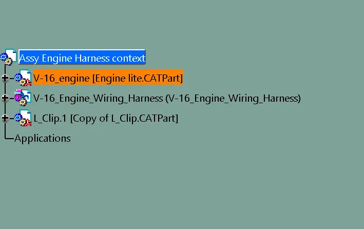
- Create Context Assembly product file
- Add 3D model of engine,and create engine wiring harness to the Context Assembly product file
- Add any metal component we need in wiring harness also add in the context as per need
Step 2
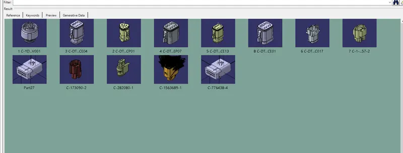
- Download the connectors given from source
- Define the connectors electrically
- Add connectors to the catalogs
- Add the connectors to the engine wiring harness file
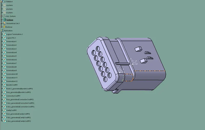
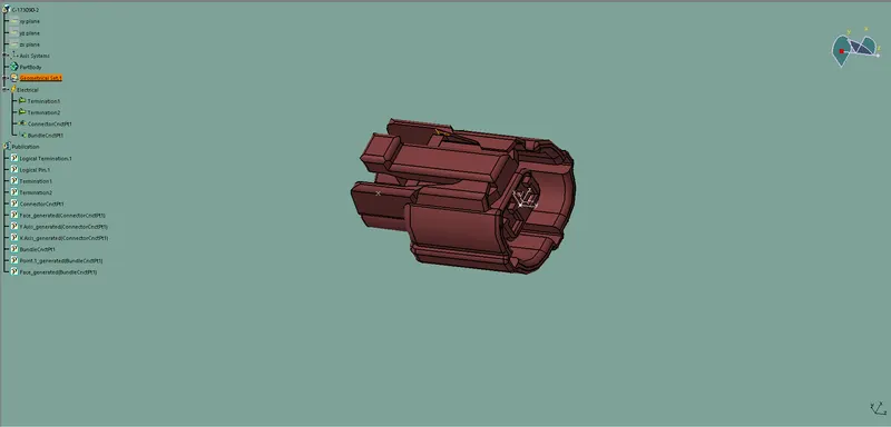
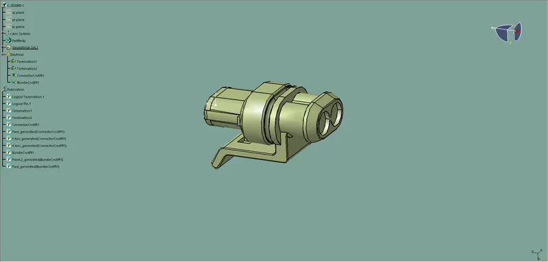
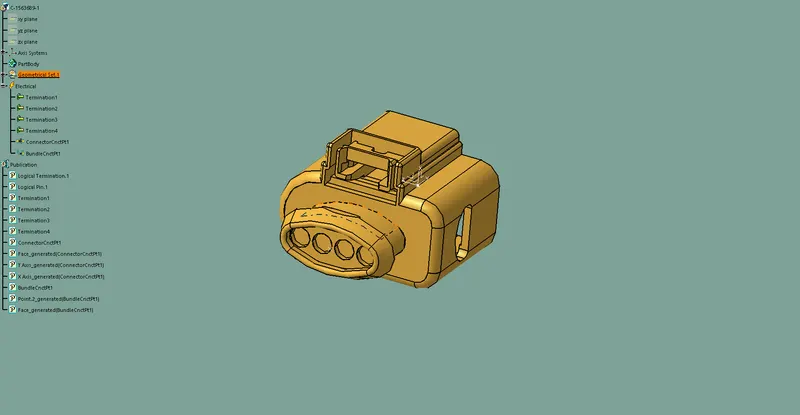
Step 3
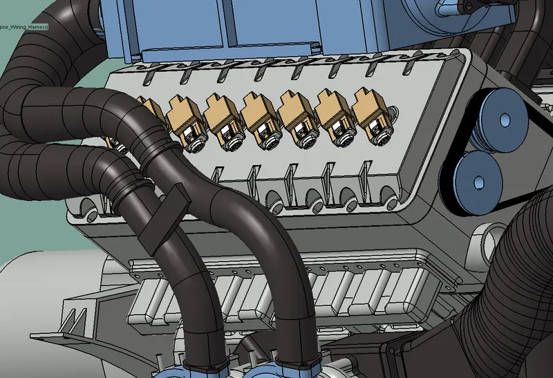
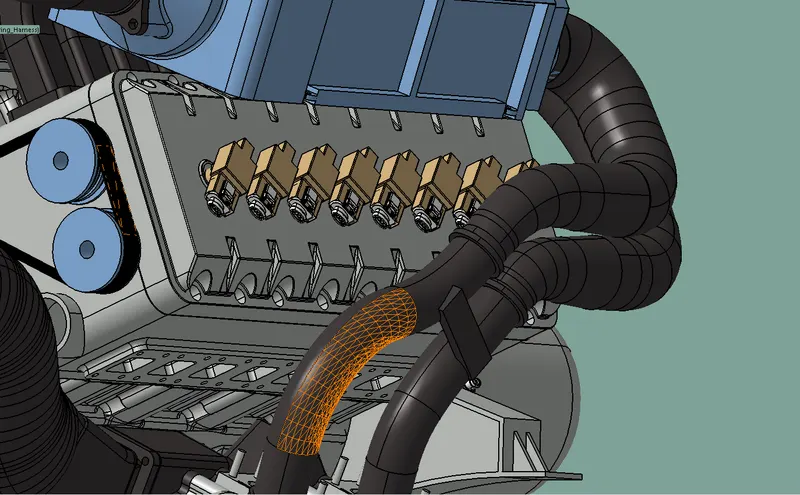
- The connectors are added to the engine wiring harness
- Positioned the connectors on the fuel injectors, neutral position sensor,camshaft senors ,vehicle Speed sensor
Step 4
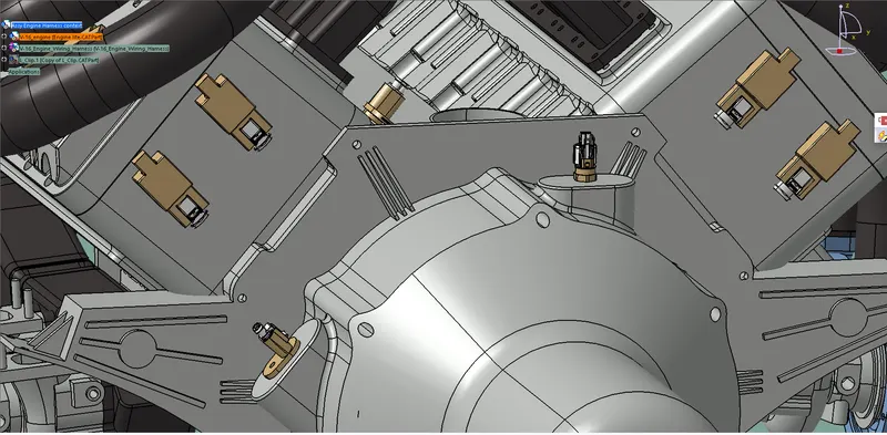
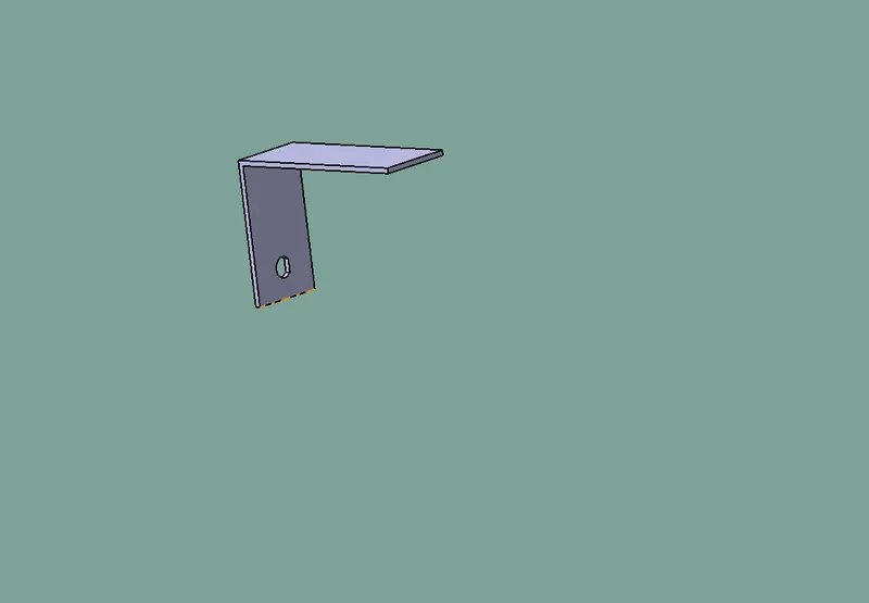
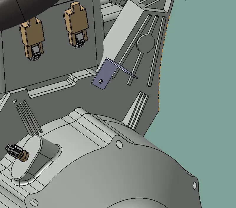
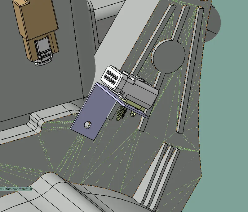
- Place the L clip on the engine to hold the interconnection connector
- Add L clip metal bracket inside of the the context assembly
- Placed it on the positioned As shown in below fig
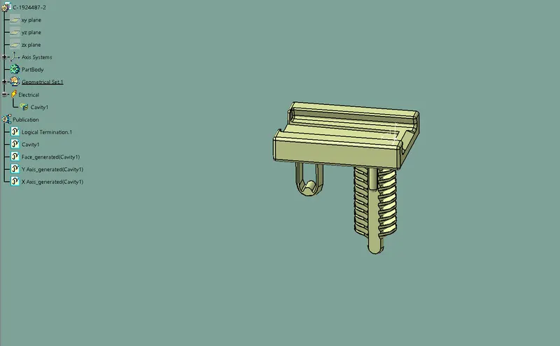
- Define the mouting clip electrically
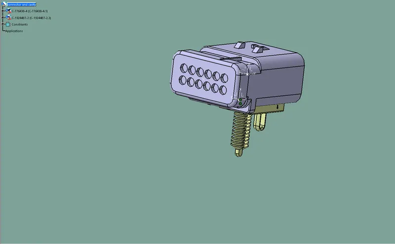
- Connect the connector and clip and Add then on the engine wiring harness
- Then mount the connector and clip on the L clip
Step 5
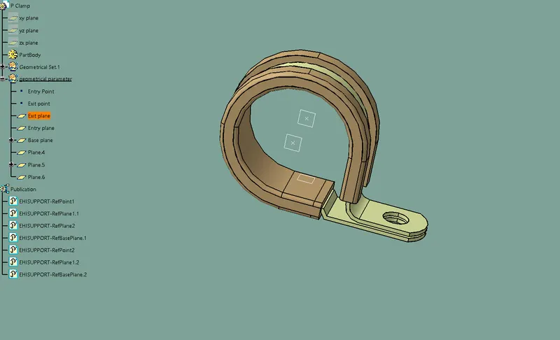
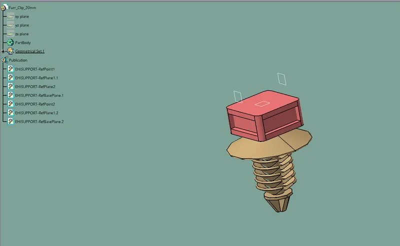
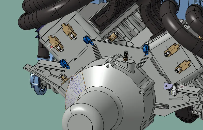
Placing the P clamp and furr tree clips to provide clamping position for wiring harness
- Define P clamp and furr tree clips electrically
- Insert then into the engine wiring harness product file
- And place P Clamp on the clamping position of the engine
- Place the furr tree clip on the engine as per industry rules
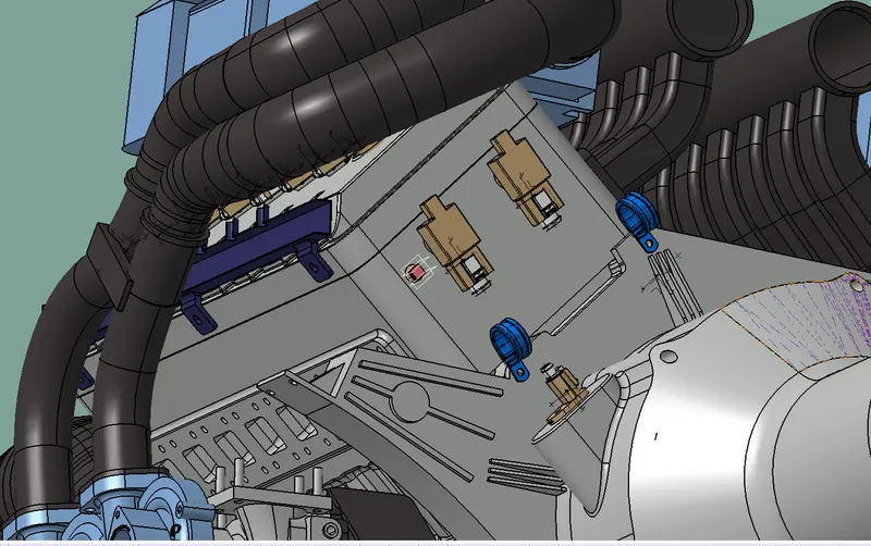
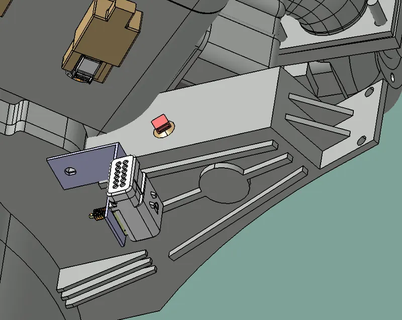
Step 6
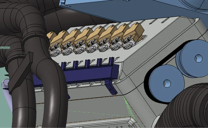
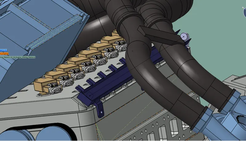
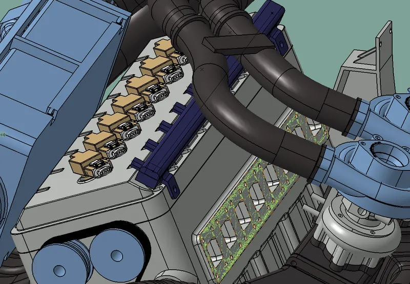
- Placing Plastic guiding channels
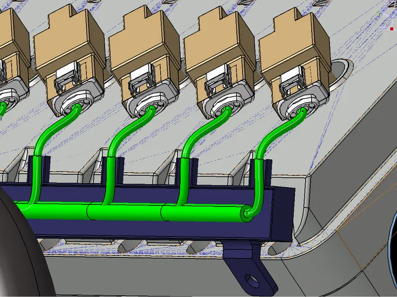
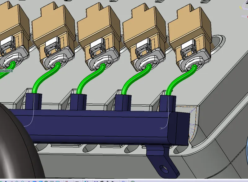
- The Engine has 8 injectors both left and right side of the engine
- The guiding channels was openly bottom is fixed and top is moveable
- Now define the guiding channels as equipment
- Insert the guiding channel into the geometrical bundle
- Now mount the guiding channel and the requrid position
- And mount the top sideof the guiding channel
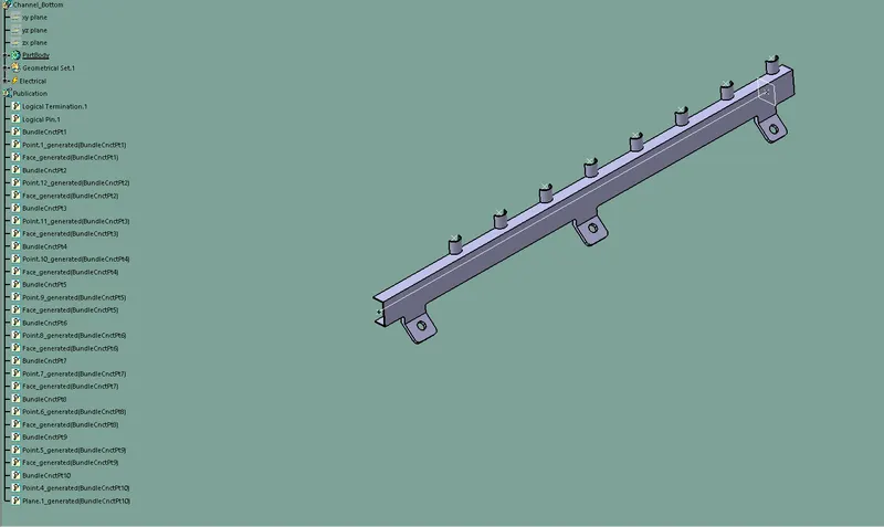
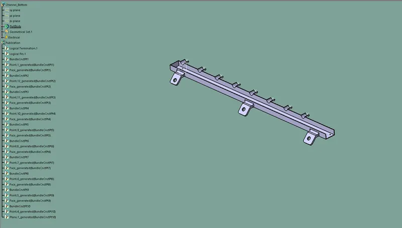
Step 7
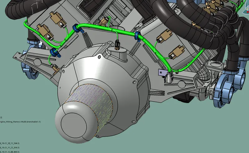
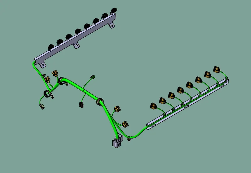
- Routing the wiring harness to the connectors
- Open electrical harness assembly workbench
- Select the geometricall bundle and now click the engine wiring harness in the tree section
- Now go to multibranchable command a tap is pop up
- Here the Bend radius ratio is 1.4 and diameter is depending of number of connection
- Then Click on the route definition
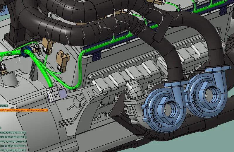
- First start from interconnection connector and continue the connection to all the connectors as shown in fig
Step 8
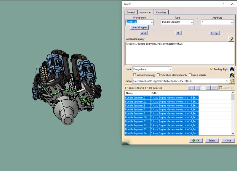
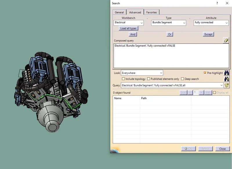
- Checking Bundle connectivity
- Now go to edit >Search > a tab pop up > click on advanced
- Now in workbench select Electrical, Type select Bundle Segment ,Attribute select fully connected
- Click search if criterian as false its showns the unconnected bunble segment ,if its true its showns all connected bundle segment
Step 9
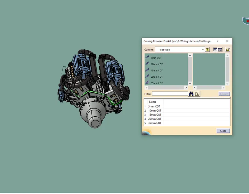
- Add protective covering to the bundle
- Create cot tube and them in the catalog
- In electrical harness assembly workbench click on protective covering command
- And apply the protective covering for the bundles wiring as shown in fig
Step 10
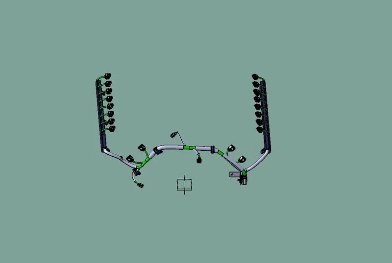
- Flattening the wiring harness bundle
- Create a New product file ,then switch to electrical harness flattening workbench
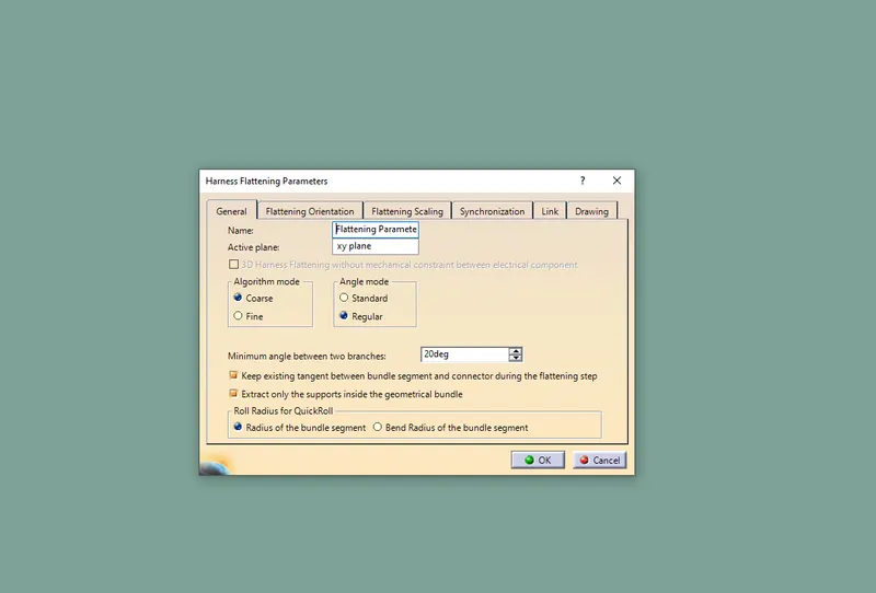
- Set the harness flattening parameters as shown in fig
- Then click command extract and now select the engine wiring harness product file