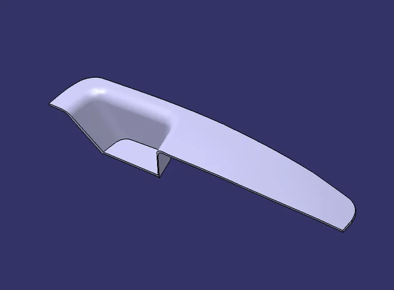
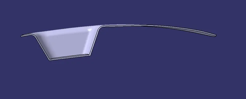
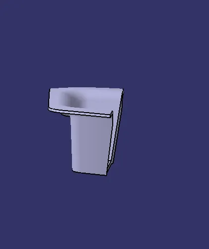
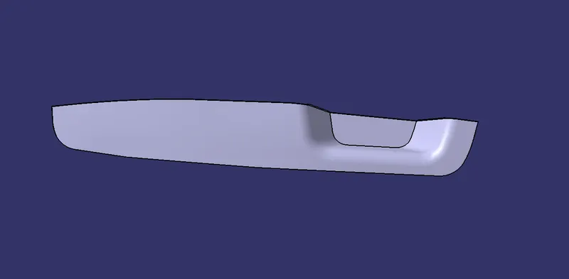
Switch Bezel Design
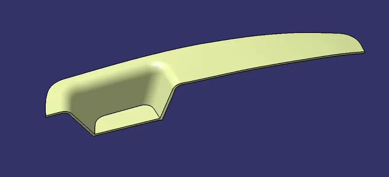
Create the Switch Bezel Plastic component through the given Class A Surface.To begin with the tooling axis for the given Class A Surface should be created the requirements of the draft angle and at the perfrom the Draft Analysis on the model
Thickness of the component to be 2.5mm
TOOLING AXIS
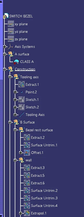
In this model we use Bicsecting line method to form tooling axis.
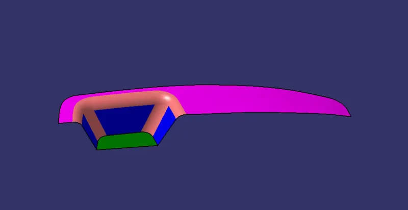
In Class A Surface select the base section and extact it and make a point centre of the surface by using point command.
Now orgin the axis system on that point.
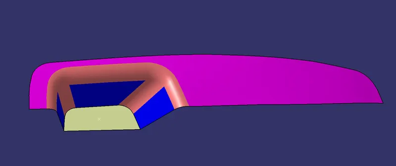
Then create a sketch On YZ plane .
Take intersection on class A and create two line on two side
Then create a bisecting line from that two lines
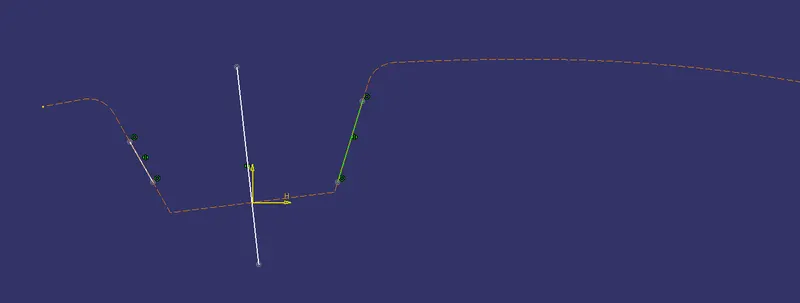
Now create a Sketch on ZX Plane
Intersection on class A and create a line on the top section and create another line from centre of axis point the angle between two line is 3 degree
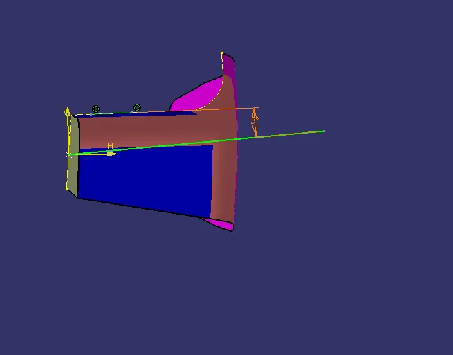
Using 1st sketch bisect line and 2nd sketch centre line Create a New bisecting line and that is tooling Axis
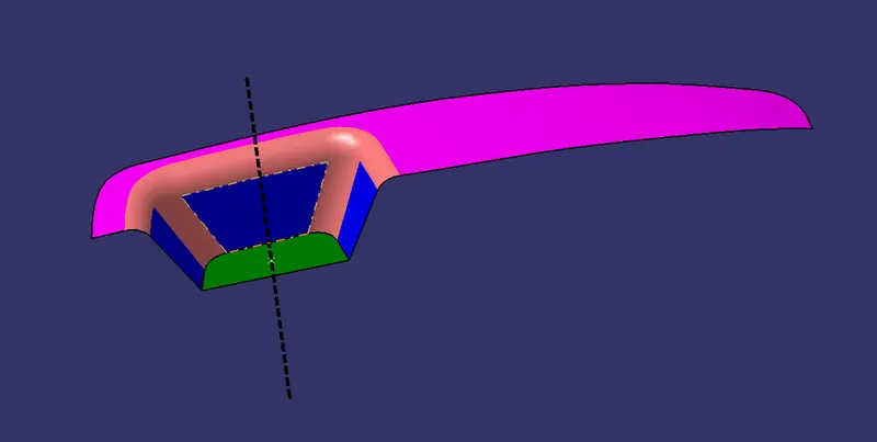
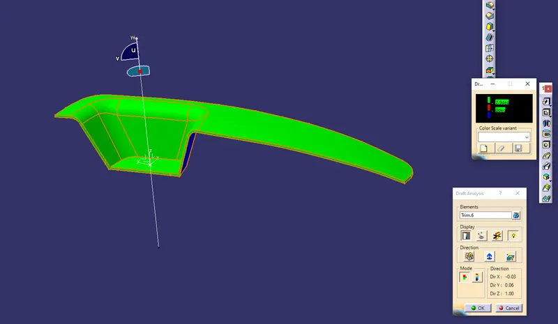
DRAFT ANALYSIS
The Drafting analysis was performed on the class A surface by using the Feature Draft Analysis Command
Using this command the compass was set on the tooling axis and the draft angle
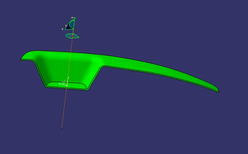
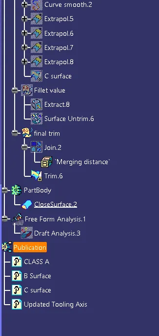
B Surface
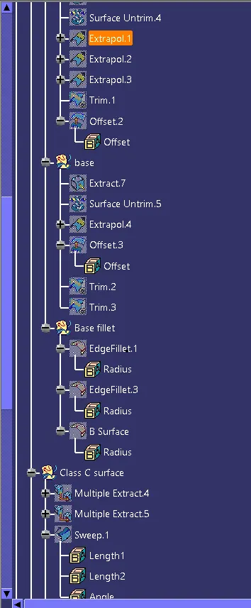
- Extract the surface from class A surface by extract command
- Then untrim the surface by using the Surface untrim command
- Now extrapol the suface
- Trim the unwanted faces from the surface by using trim command
- Then offset the final suface 2.5mm
- Then fillet the egdes by fillet command
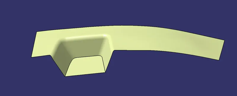
C Surface
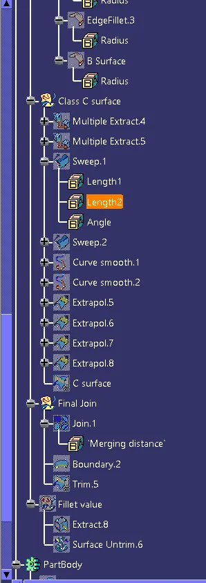
- Boundary the edge of the Class A Surface By Multiple Extract command
- Using the sweep command select the boundary and sweep down for the angle of 3 degree
- And using Curve smooth command smooth the c Surface
- Then extra the egdes and trim the unwanted section

Then join and trim the surface A B C