Core & Cavity Design
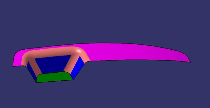
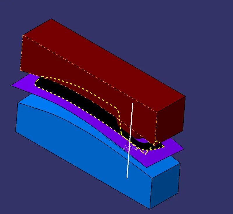
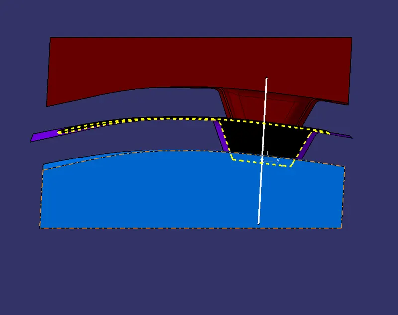
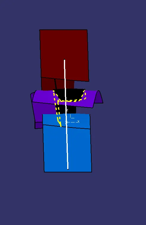
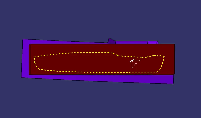
In this model we use Bicsectinh line method to form tooling axis
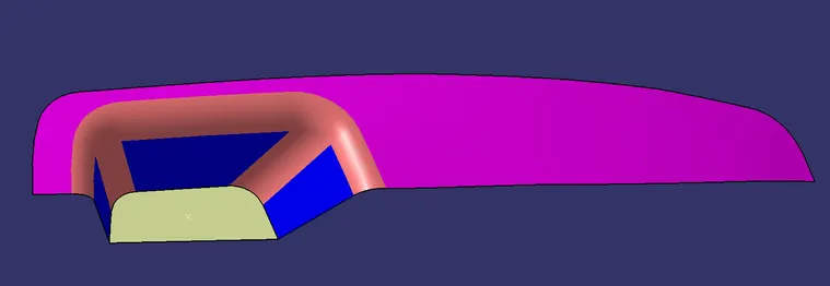
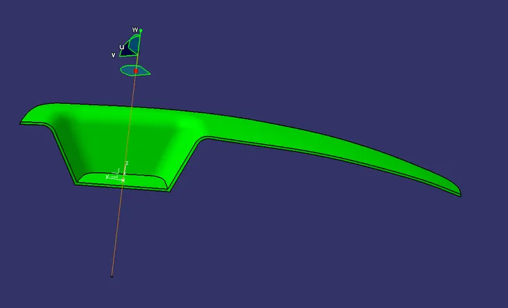
In Class A surface select the base section abnd extact it and make a point centre of the surface by using point command
Now orgin the axis system on that point
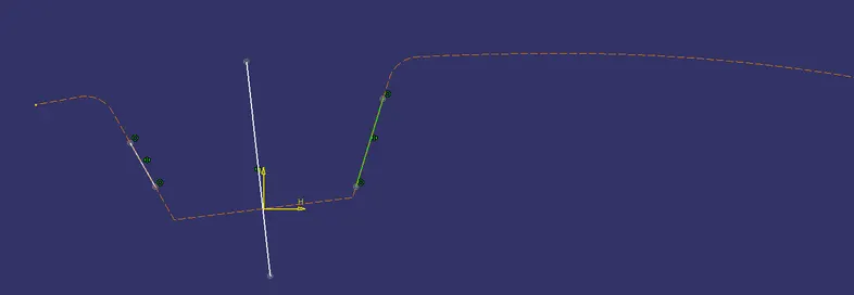
Then ceate a sketch on YZ plane
Take intersection on class A and create two line on two side
Then create a bisecting from that two lines
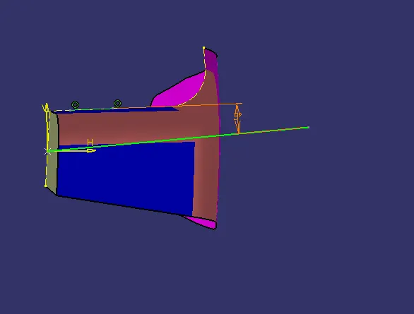
Now create a sketch on ZX plane
Intersection pn class A and create a line on the top section and createe another line from centre of axis point the angle between two line is 3 degree
Using 1st sketch bisect line and 2nd sketch centre line create a new Bisecting line and that is tooling Axis
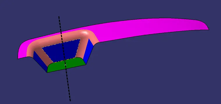
DRAFT ANALYSIS
The drafting Analysis was performed on the class A surface by using the feature Draft Analysis command
Using this command the compass was set on the tooling axis and the draft angle