Week 4 Challenge
1 Define tooling direction
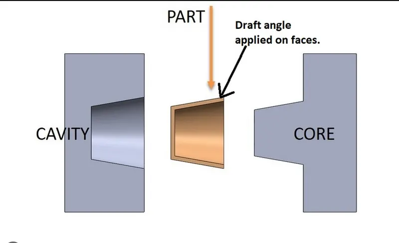
Tooling direction refers to the specific direction in which the components of a mold, such as the core and cavity, separate from each other during the molding process. It determines how the mold opens or pulls apart to allow for the ejection of the molded part.
The tooling direction is an essential consideration in mold design as it influences the mold's shape, features, and the placement of the parting line (dyeline). Properly planning and optimizing the tooling direction ensures smooth and efficient production, preventing issues such as part sticking, damage to the mold or part, and production delays.
By analyzing the geometry and requirements of the part being molded, designers determine the best tooling direction that allows for easy part ejection without any interference or deformation. Factors such as part geometry, undercuts, draft angles, and the overall complexity of the part influence the selection of the tooling direction.
It is common to design molds with a split-line, which is the area where the core and cavity separate. This split-line corresponds to the tooling direction and is strategically positioned to achieve optimal part ejection and mold functionality.
2 Create tooling direction for Class A with 10 deg draft ( draft in command should be 10 deg) and show the draft analysis
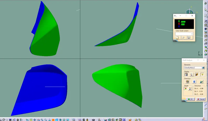
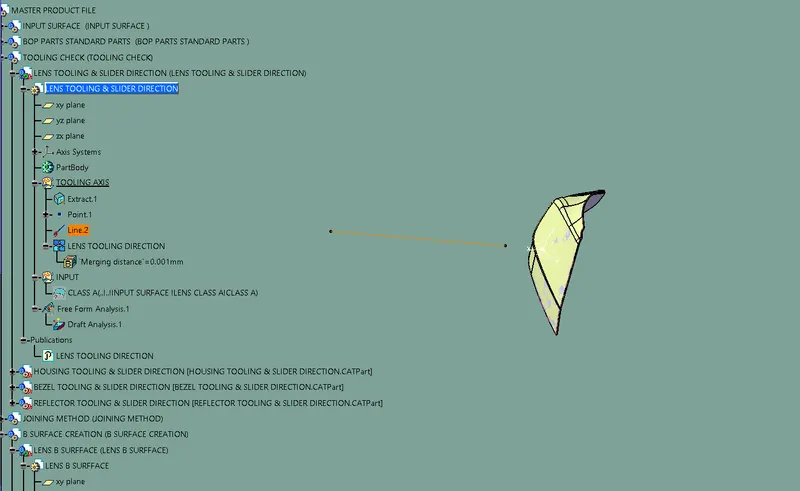
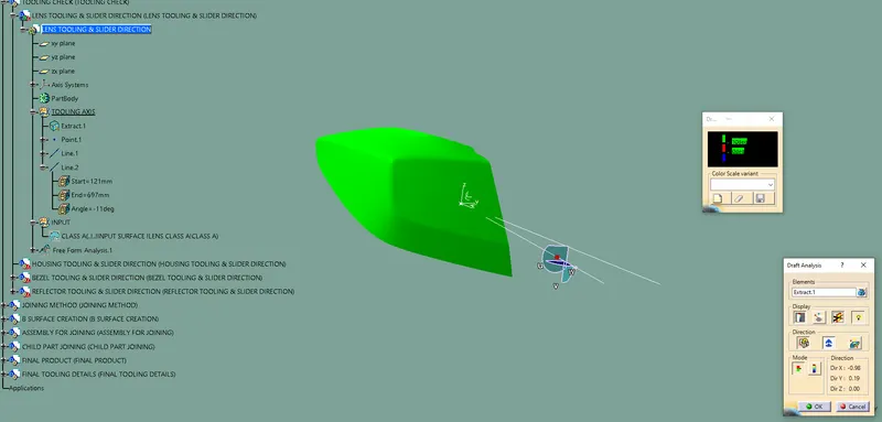
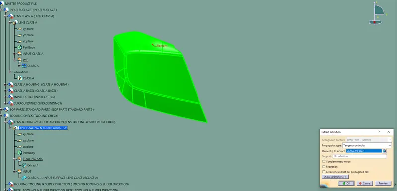
To start, it is necessary to establish a point and axis system within the provided Class A surface of the lens. Next, generate a simulated line based on a specific point and the x direction, and assess the direction of draft.If the draft analysis does not meet the requirements, an alternative approach would be to generate an additional line originating from the dummy tooling axis, this time at an angle of 10 degrees.After conducting the draft analysis with a 10-degree angle and determining that it meets the necessary criteria, proceed to establish the tooling direction for the lens component.
3 Write the definition of the Parting line
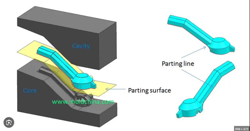
The parting line, in the context of industrial casting or plastic injection molding, is the boundary or line of separation where the two halves of a mold or injection mold meet. It represents the interface between the core and cavity halves of the mold or between the two halves of the injection mold. The parting line serves as a reference for the mold's parting surface and indicates the direction in which draft angles change. In casting, it is the borderline where the mold is split into two halves, allowing for the removal of the molded part. In injection molding, the parting line is the line of separation on the molded plastic part where the two halves of the injection mold come together, defining the parting plane. Proper design and consideration of the parting line are crucial for achieving high-quality molded parts with desired aesthetics, functionality, and manufacturability.
4 Create B surface of the given lens in surface modeling (not in part), with a 4 mm thickness
Offset the given class A surface with 4 mm.
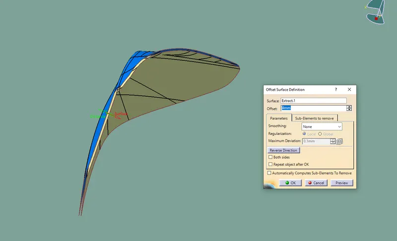
The surface has some issue
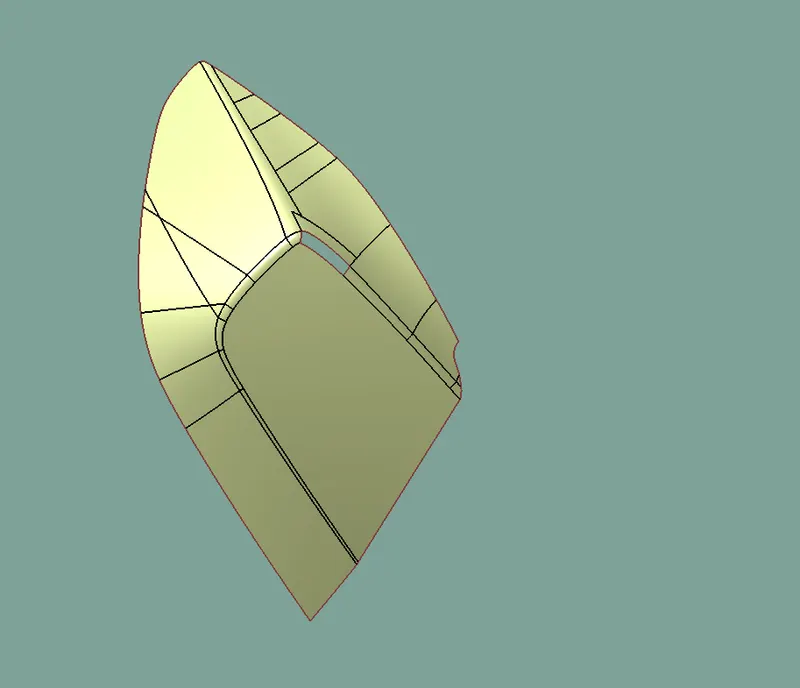
This is CLASS B SURFACE
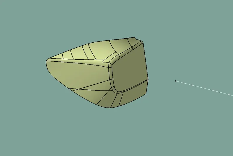
Create C surface:
create sweep from the edge of Class A surface with respect to surface and 3-degree angle.
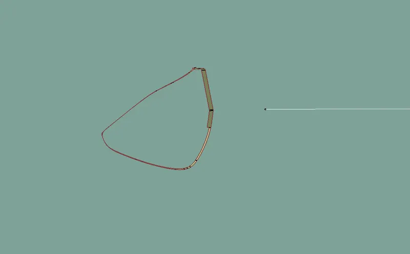
CLASS A +C
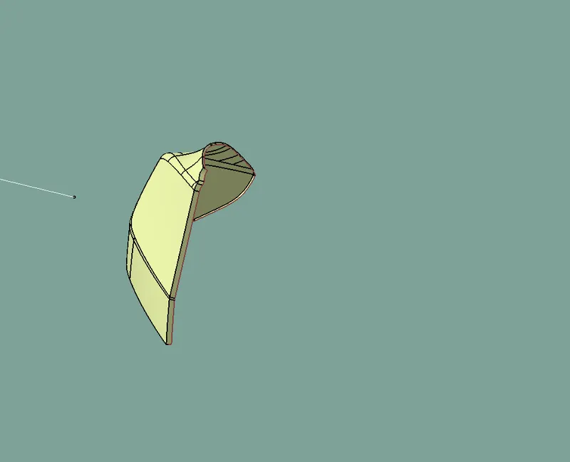
The final component of the Lens
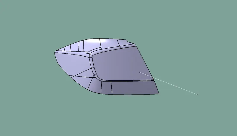
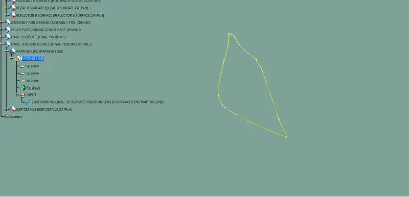
5 Create a Parting Line for thickened lens and create a report for how you approached the parting Line and did a draft analysis?
In the injection molding process of a two-color mold, the selection of the parting line is influenced by both the design and appearance requirements of the product, as well as the feasibility of the manufacturing process and the positioning of subsequent mold layout components. Generally, the determination of the parting line can be categorized as follows:
-
If a straight line intersects the surface of the object at a single point, that point is considered a point on the parting line.
-
If a straight line intersects the object's surface as a straight line segment, any point along that segment can be chosen as a point on the parting line. The selection of the specific point is typically based on principles such as the shortest connection with adjacent points. This determination can also be done interactively.
-
In cases where the line intersects the object at multiple points or segments, it indicates that the intersection of the overall approach cone and the mold opening direction is zero. In such scenarios, the design of the mold should incorporate core pulling in this region. The parting line of the mold will then be determined based on the shape and size requirements of the core pulling mechanism.
These considerations help ensure that the parting line is appropriately determined in two-color mold injection molding, taking into account both the aesthetics and the practical aspects of the manufacturing process.