Developing a Door trim panel from the given class A and master sections and also create the attachment features
AIM:
To develop a Door trim panel from the given class A and master sections and also create the attachment features
OBJECTIVE:
- To create individual tooling axis for the parts and perfrom draft analysis on the class A surface.
- To createnthe class B and class C surface from the given class A surface.
- To form a solid geometry by combining all the surface .
- To decide an attachment strategy ffor the part and creat engineering features in refference from the master section provided.
- To perfrom draft analysis on the solid part model part model with all engineering features.
- To assemble all the components together to obtain the final trim.
DOOR TRIM PANEL
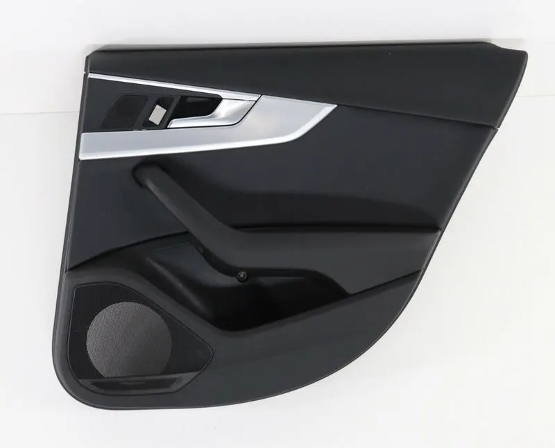
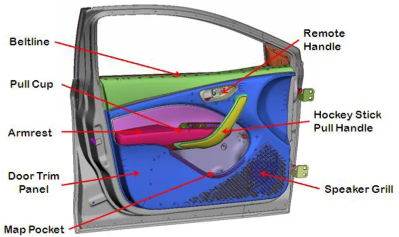
A door trim panel is an interior component of a car door that cover the door's inner workings such as the window regulator wiring and door lock mechanism . its also known as a door panel or door card
The door trim panel is usually made of plastic, vinyl or other materials and is attached to the door frame with clips or screws. it may have various features such as door handles, armrests power window switches and speakers for the car's audio system.
The design and appearance of the door trim panel can vary depending on the make and model of the car as well as the trim level .Some may have a simple design with minimal features while others may have a more elaborate design with decorative accents and high end materials
GIVEN INPUTS
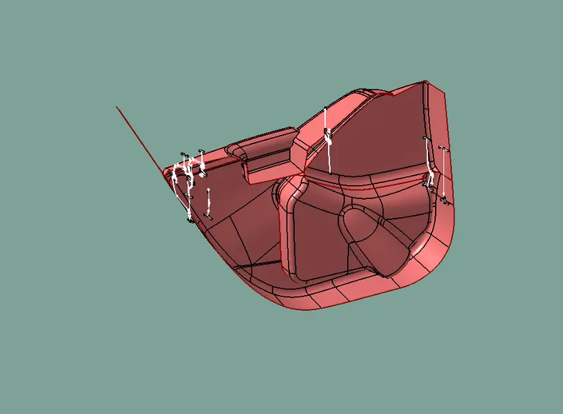

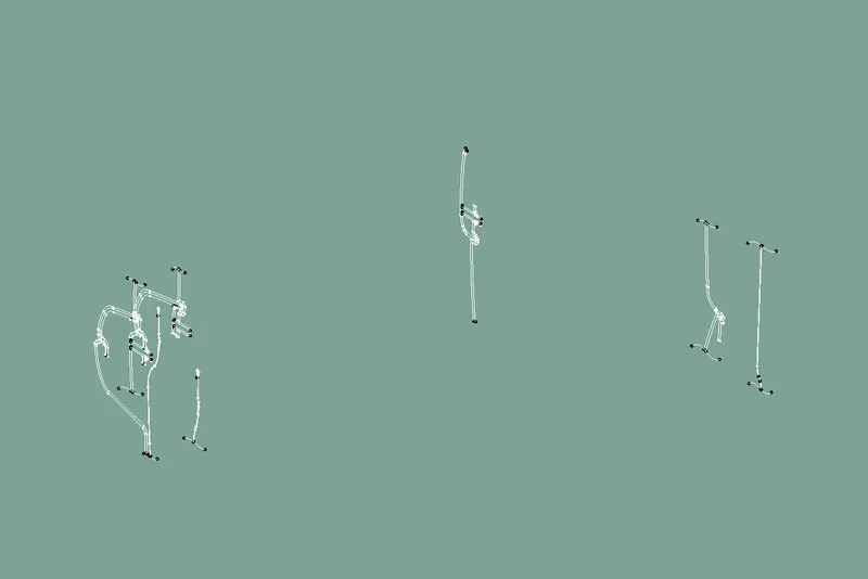
FILE CREATING
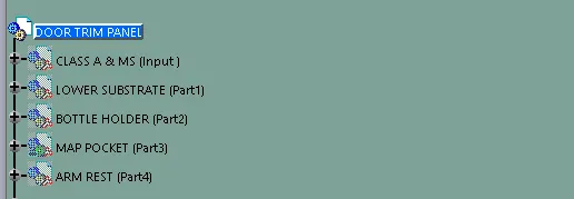
- In catia create a product file and Door trim panel
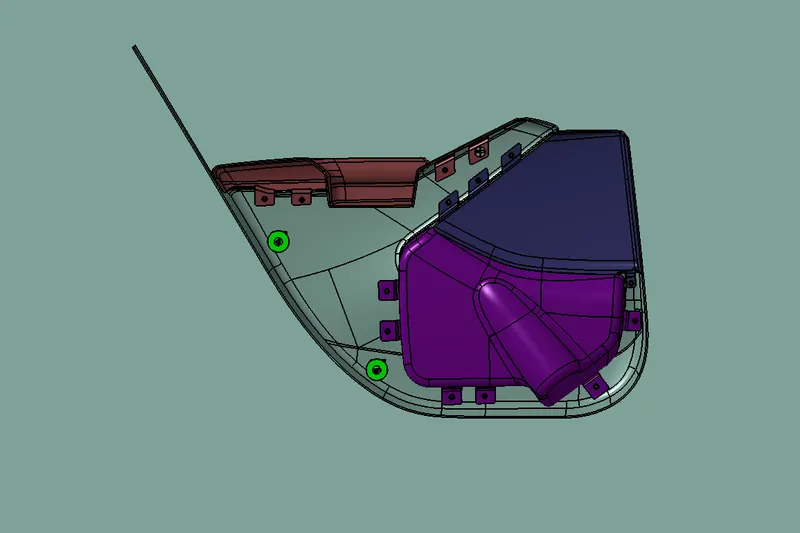
- In that create part file to add all the components of the door trim panel i.e. the Arm Rest, Lower Substrate, Bottle Holder & Map Pocket
TOOLING AXIS
- To create the tooling axis for the class A surface,of each component
- Check for any disscontinuities in the class A surface
- If found make the required improvements
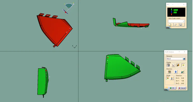
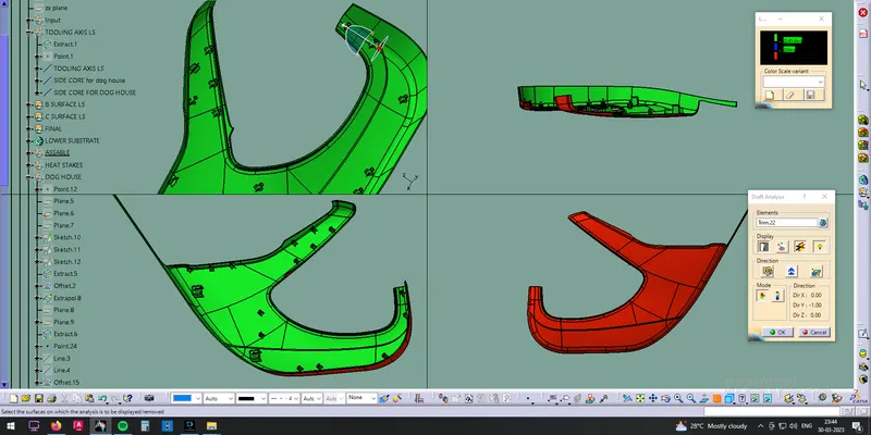
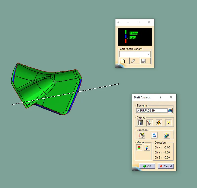
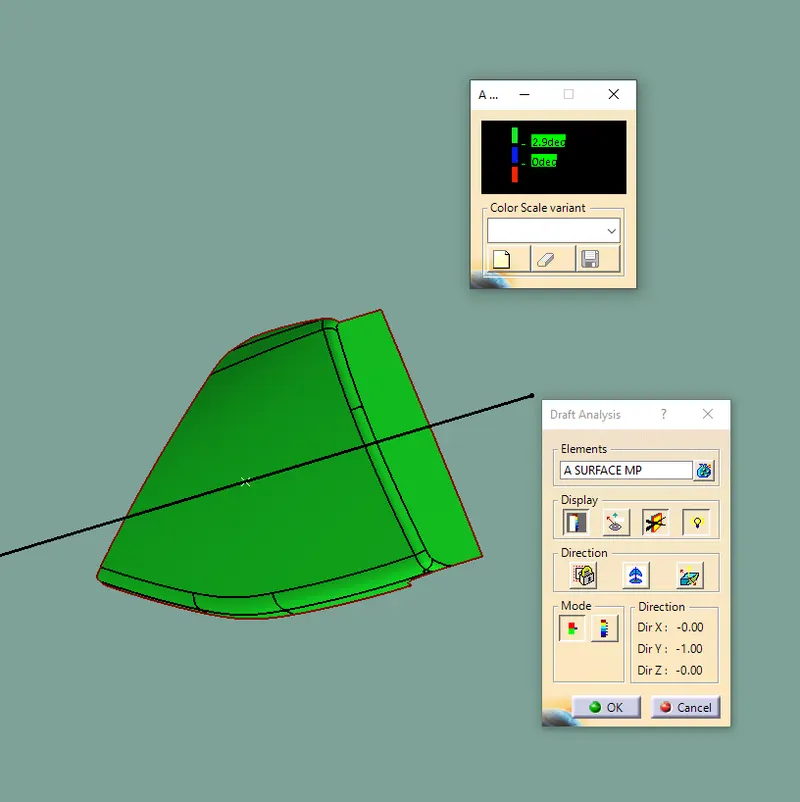
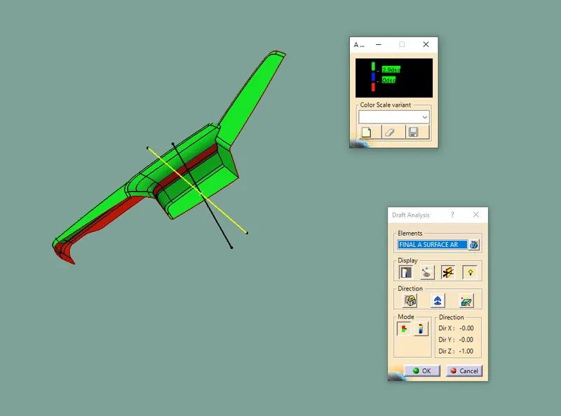
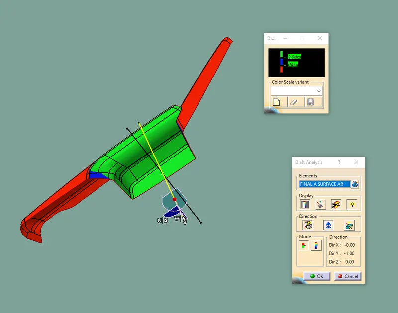
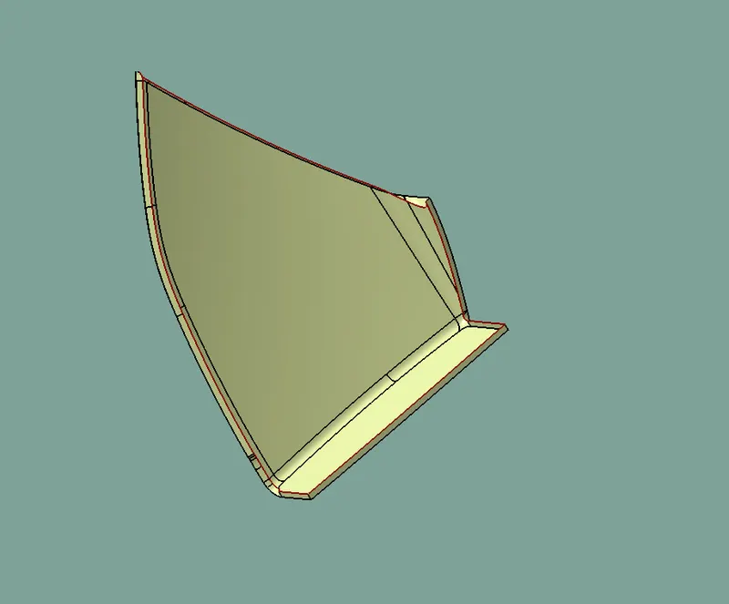
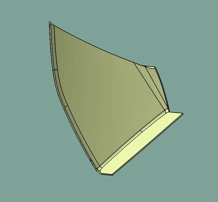
DRAFT ANALYSIS FOR CLASS A SURFACE
- Go to INSERT -> ANALYSIS -> FEATURE DRAFT ANALYSIS
- Now move the compress to the tooling axis and lock it
- Change the range to 3 to 2.8 Deg .
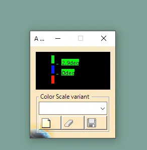
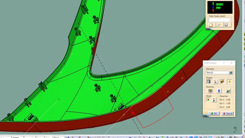
- The input Clas A also has walls having negative angle to the tooling axis
- This can be an issue while manufacturing the component as it would be very difficult to draw from molds.
- So this design needs to consider various side tooling options
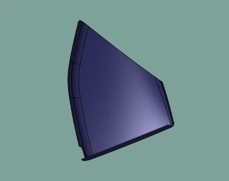
TOOLING AXIS FOR LOWER SUBSTRATE
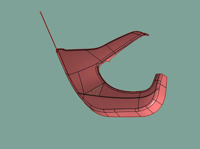
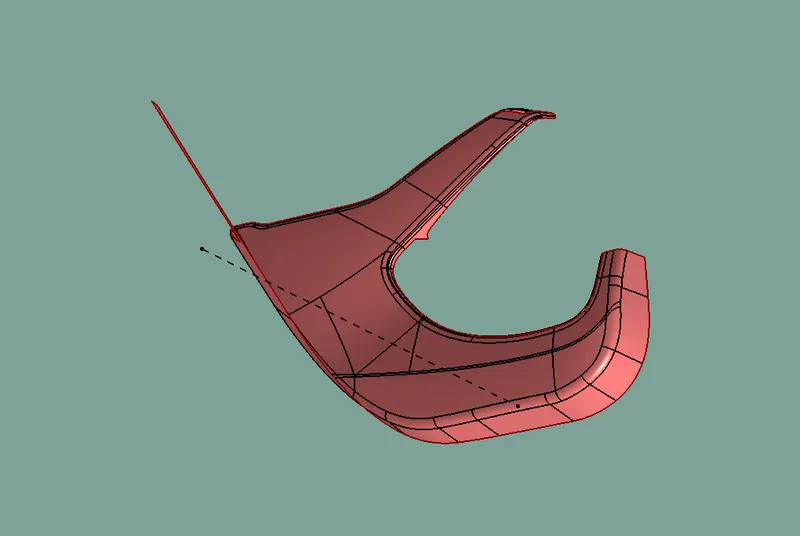
DRAFT ANAYLSIS FOR CLASS A LOWER SUBSTRATE
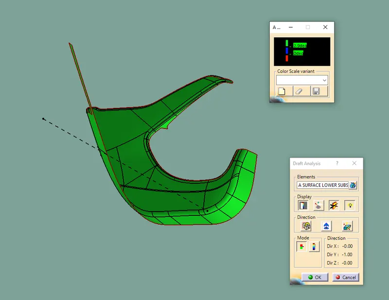
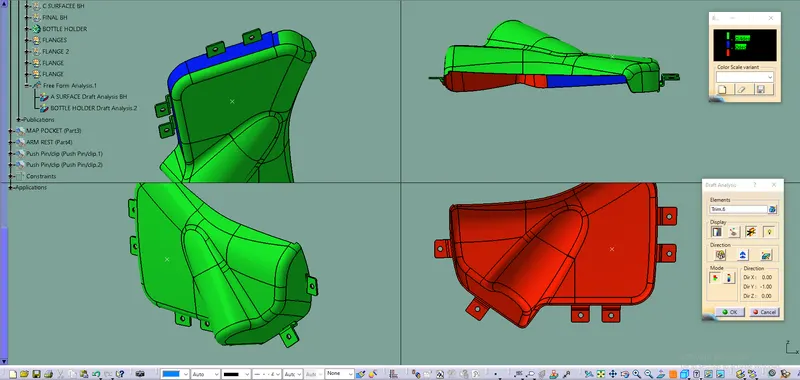
TOOLING AXIS FOR BOTTLE HOLDER
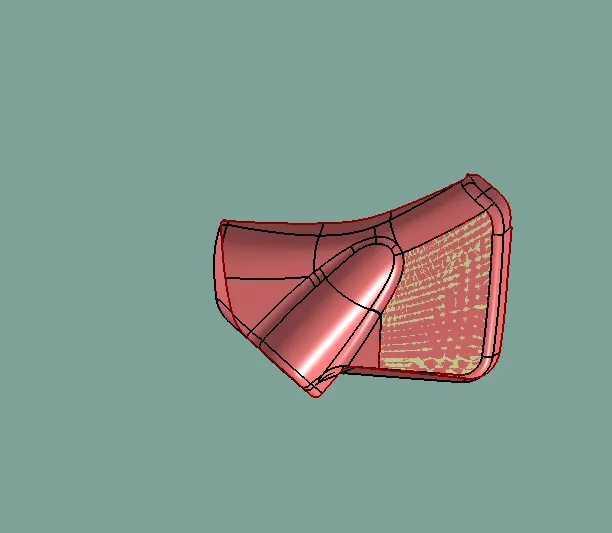
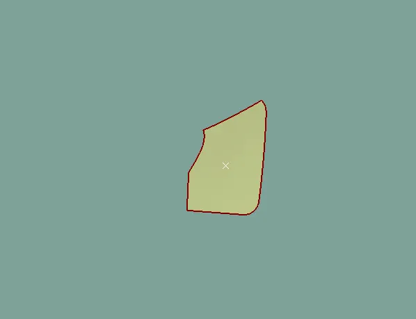
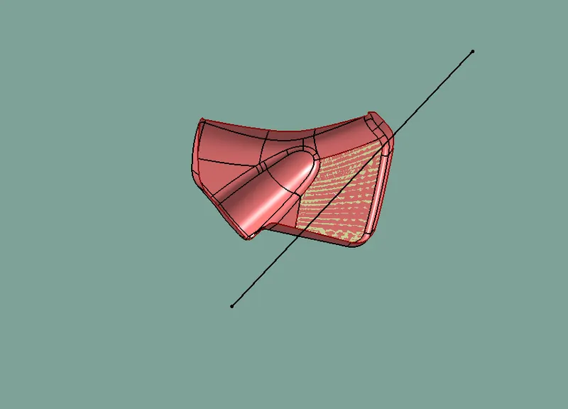
DRAFT ANAYLSIS CLASS A BOTTLE HOLDER
TOOLING AXIS FOR MAP POCKET
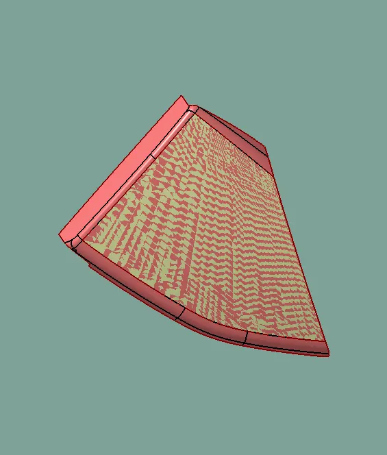
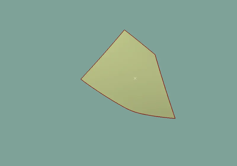
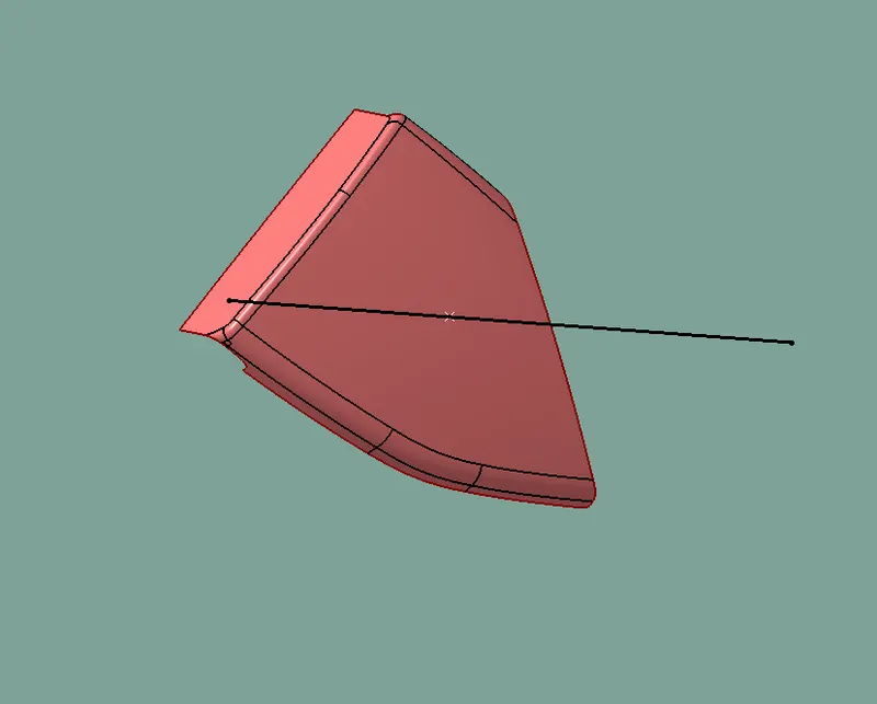
DRAFT ANAYLSIS CLASS A MAP POCKET
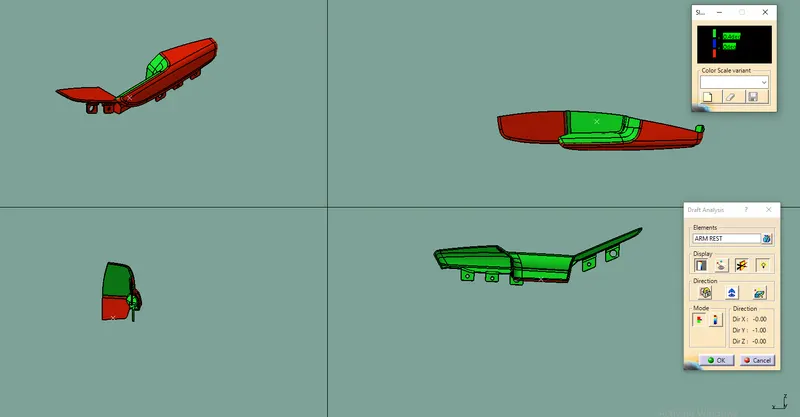
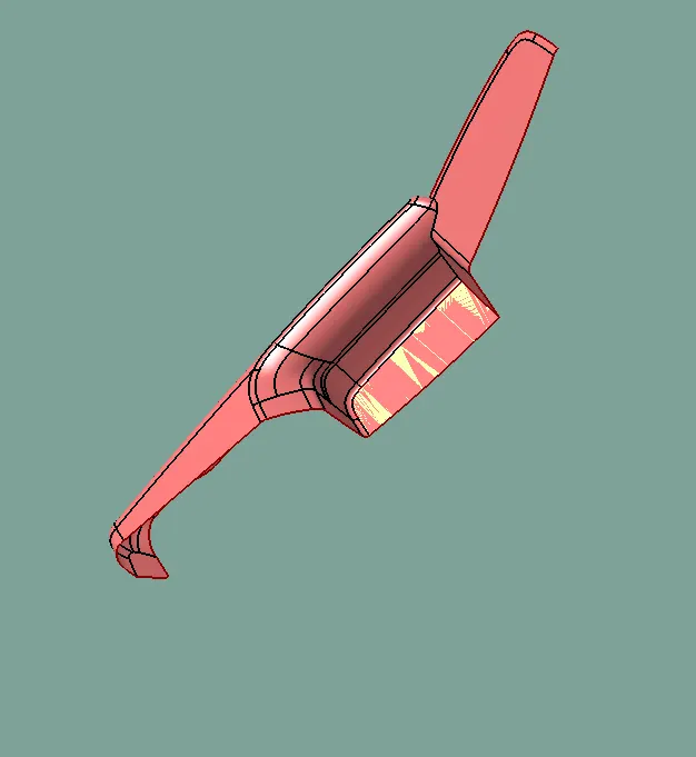
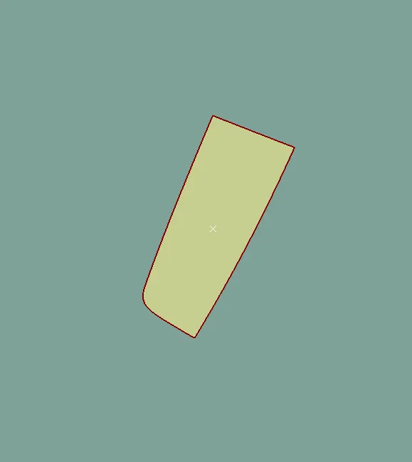
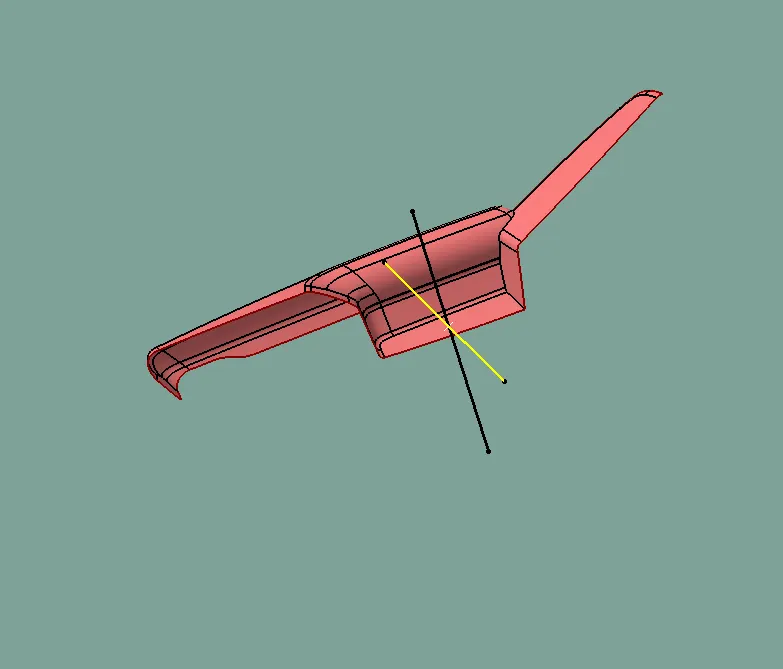
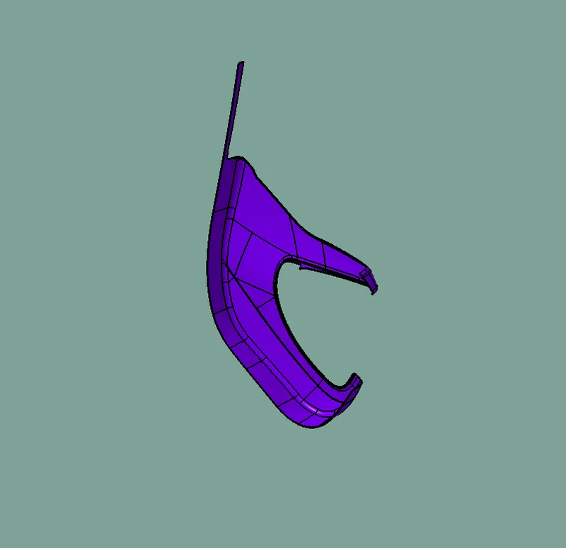
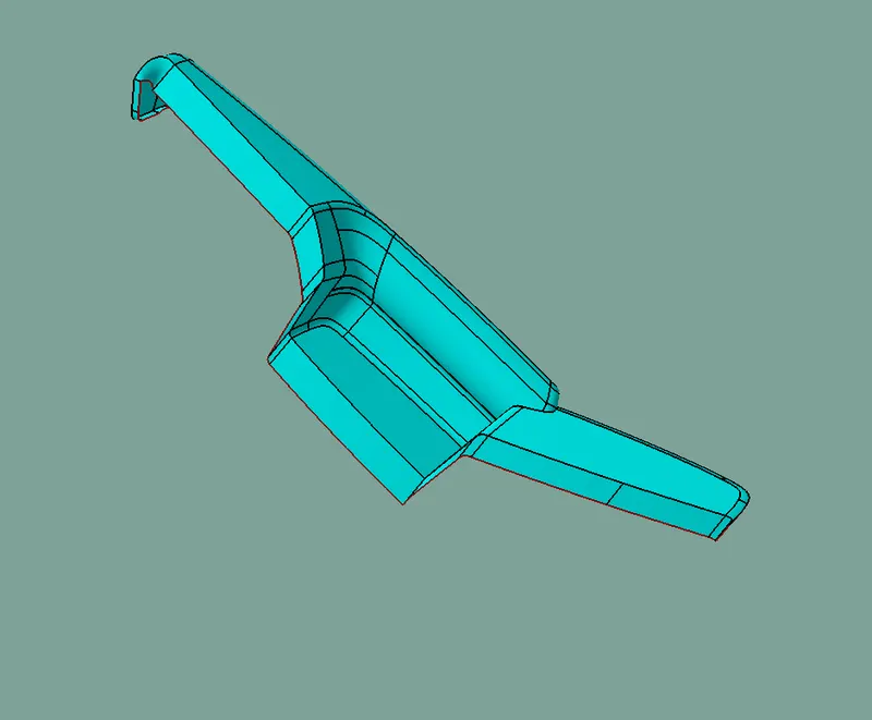
TOOLING AXIS FOR ARM REST
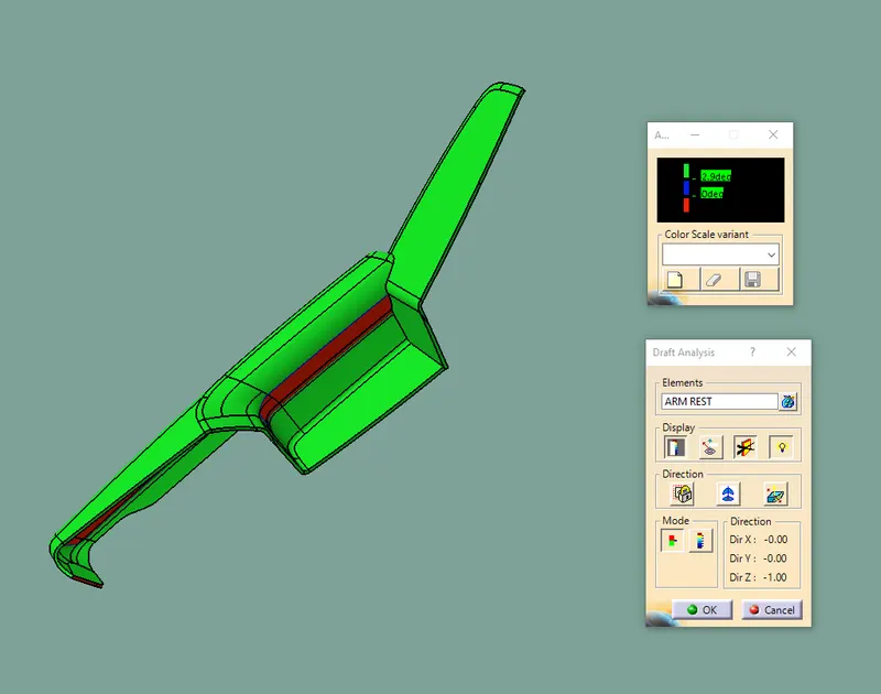
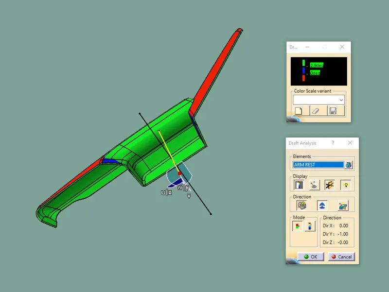
DRAFT ANAYLSIS FOR CLASS A SURFACE ARM REST
CREATION OF CLASS B SURFACE
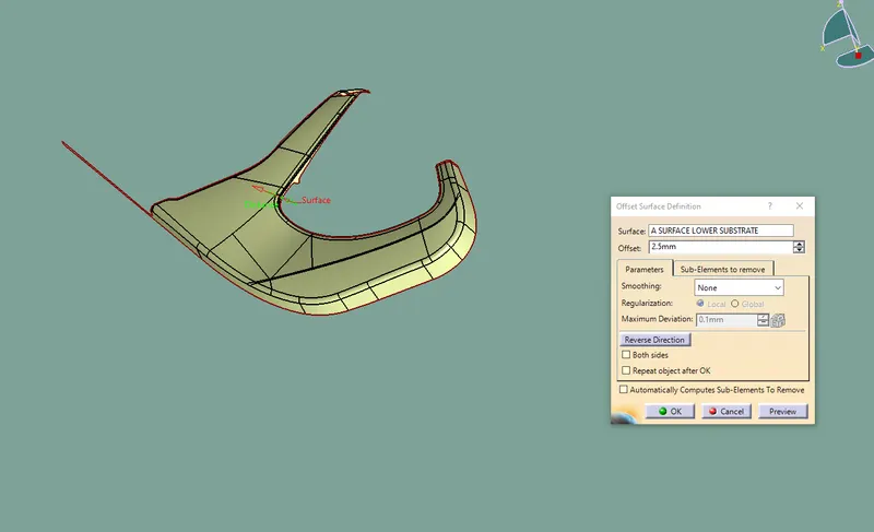
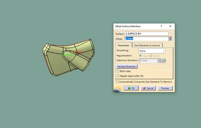
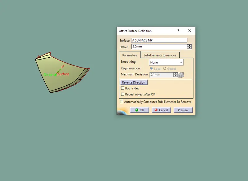
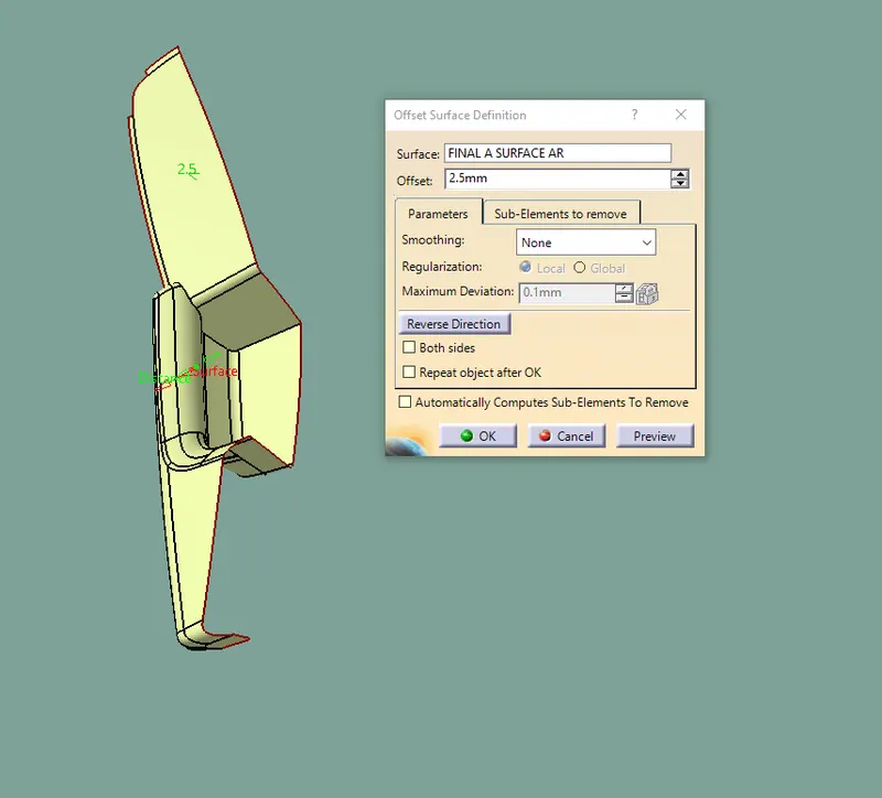
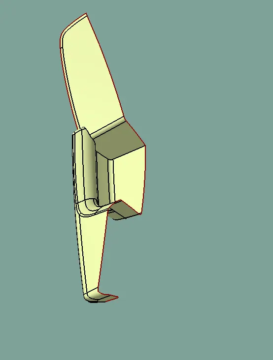
Class B surface has been created by offsetting of class A surface .Offsetting has been done using the offest command .Class A surface is offset with a 2.5 distance.Surfaces that were not offsetting were formed using Muilt section , join, trim commands
CREATION OF CLASS C SURFACE
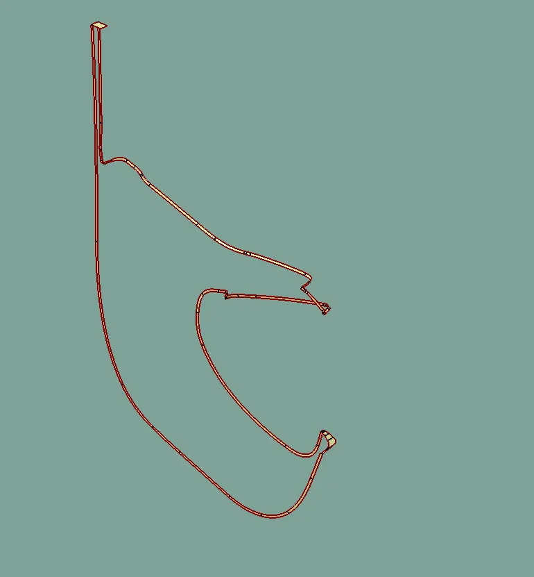
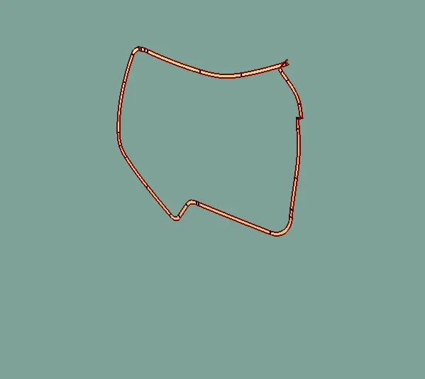
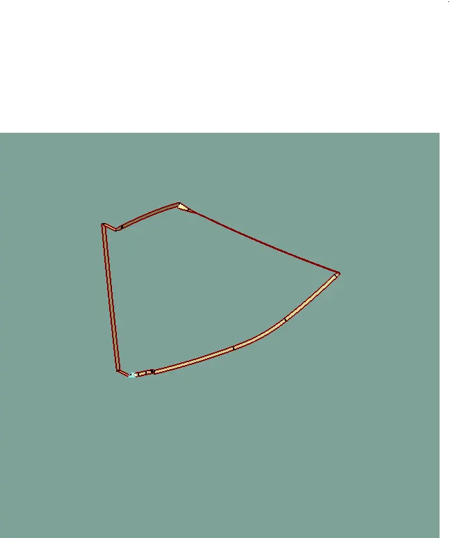
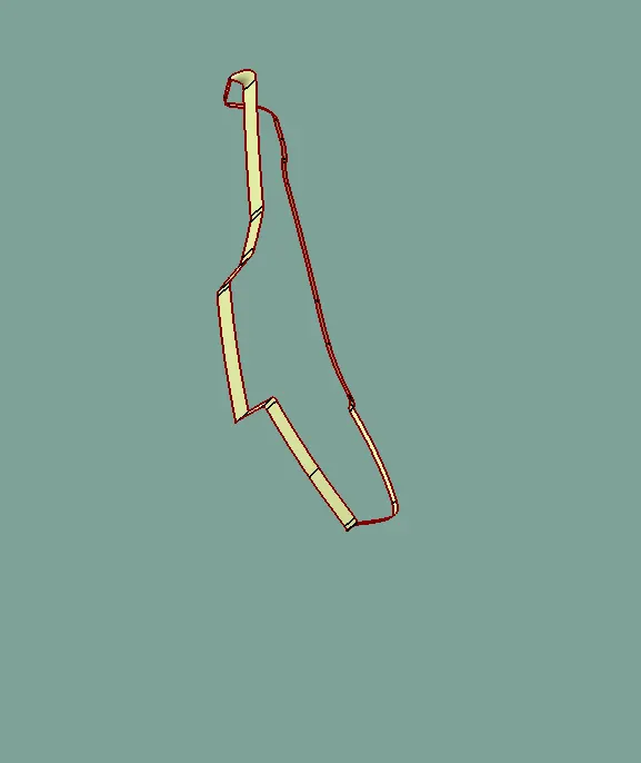
Using the multiple extact commands , boundaries of the class A surface were extracted . Class C surface joins class A and B surafce . It is Created using the sweep command. Inputs for the sweep coommand were extacted boundary class A surface angle value and length of the sweep hence several sweeps and multisection were created and finallt they joined together to createe a class C surface
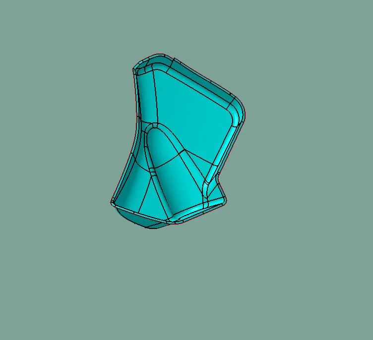
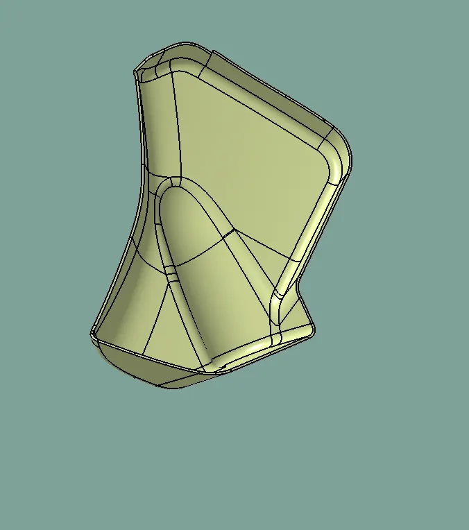
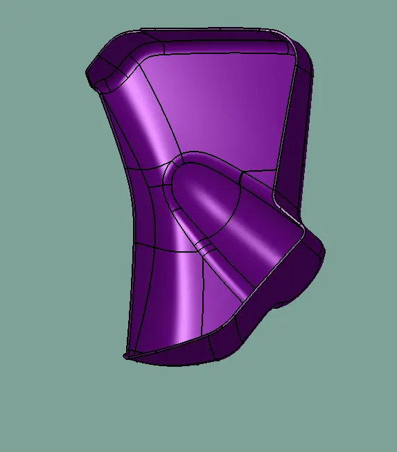
FINAL JOIN AND TRIM AND CLOSED BODY CREATION
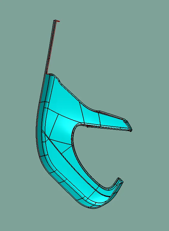
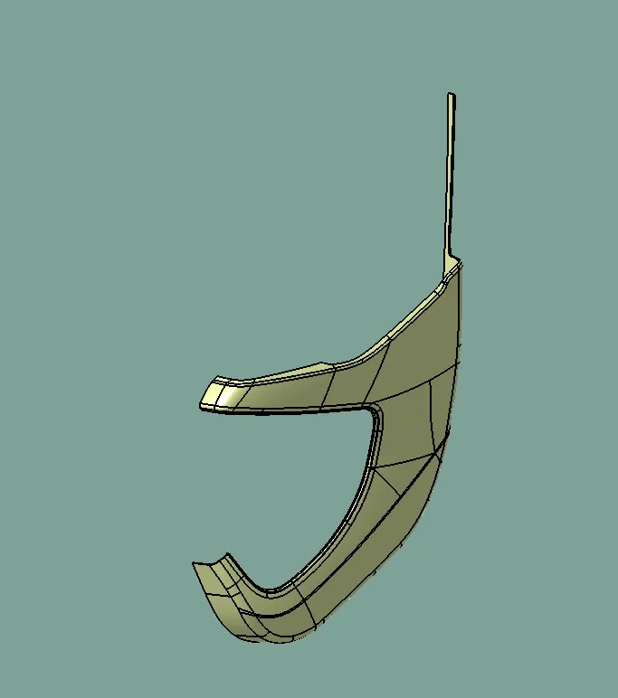
The join of class A and Class C surface is trimmed with class B surface to surface to create a closed surface. While performing trim operation errors were coming as a proper intersection was not happening . Hence with the help of extrapolating command class B surface was extrapolated and finally trimmed
The close surface was confirmed using the boundary command .By clicking on surface warning popped up stating the surface is close and it has no boundaries .This is the trick often used to check wherther the surface is close or not. if it is closed surface then go to part design and thicken the closed surface .
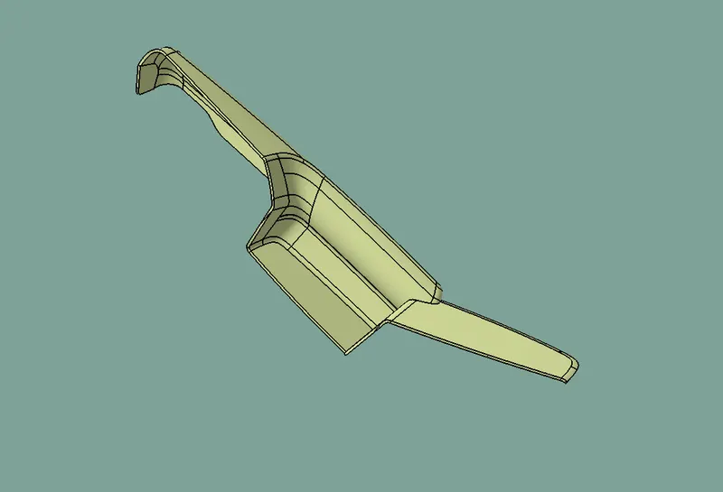
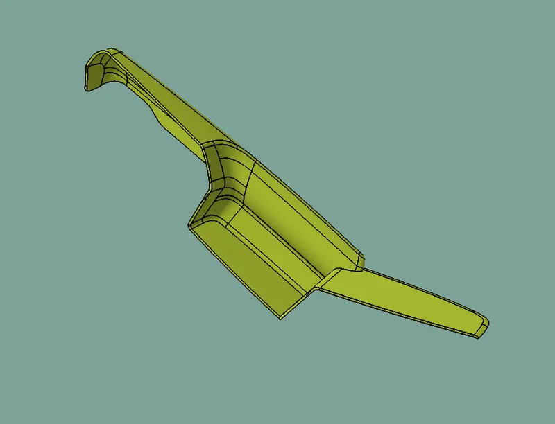
PERFORM DRAFFT ANALYSIS ON CLOSED SURAFCE
- Change View mode customization to Material Mode
- Go to DRAFT ANALYSIS and move the compass to the Main tooling axis
- Change the range to 3 to 2.8 deg
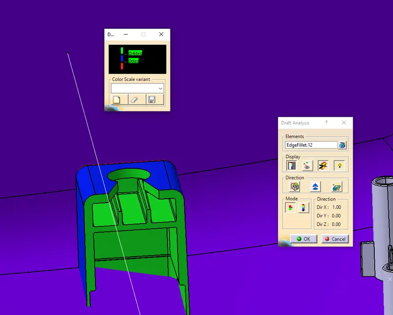
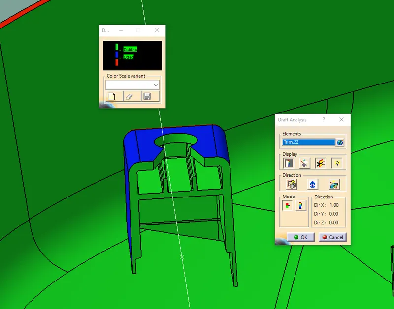
COLOUR REPRESENTION
GREEN - POSITIVE DRAFT
BLUE - ZERO DRAFT
RED - NEGATIVE
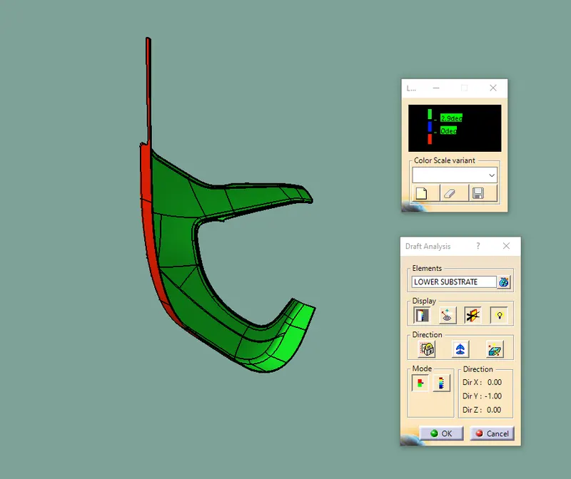
FOR BOTTLE HOLDER CLASS A SURFACE HAS SOME DRAFT ISSUE SO ZERO DRAFT IN SOME AREAS
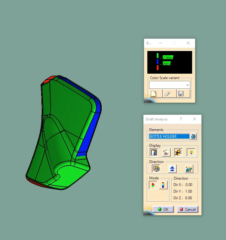
This would lead to ejection problems while molding process.Hence the class A surface has to be modified tp meet draft
requirements hence we have created tooling for all components
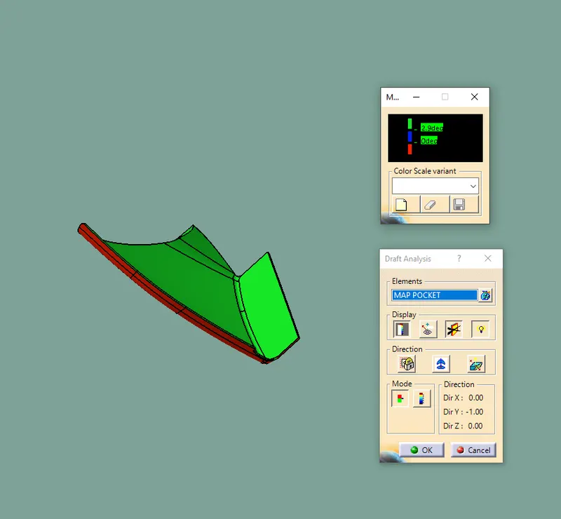
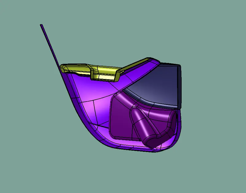
ARM REST NEED SIDE CORE
HEAT STAKE CREATION
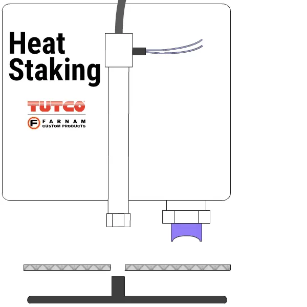
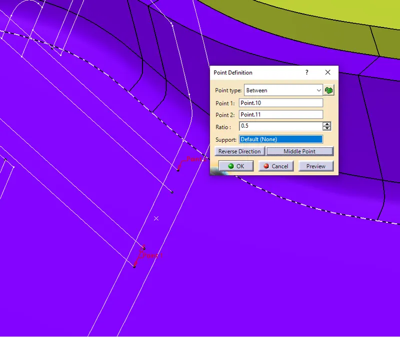
- By using master section Create a point centre of the master section by using between point command
- Isolate the point
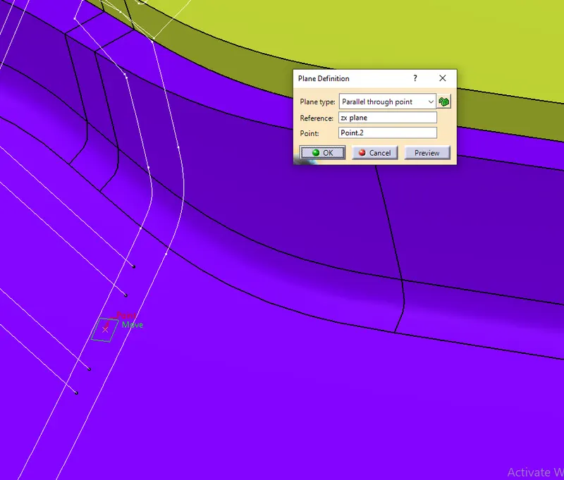
- Then create a plane by using parallel through point in ZX PLANE
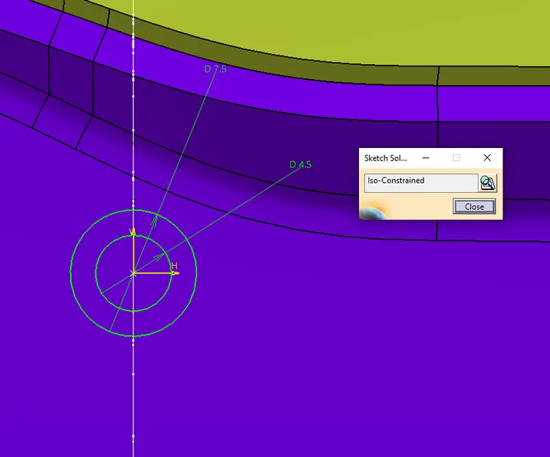
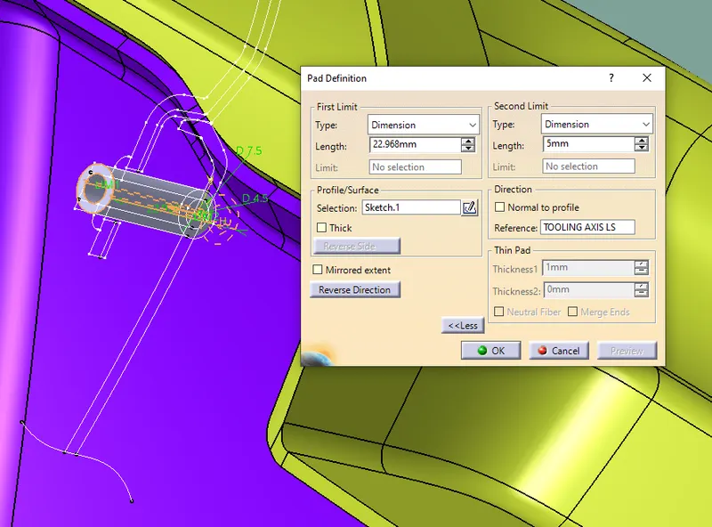
- Using positioning sketch to draw the inner and outer cricle of heat stakes
- By using pad command thicken it the height is take for master section
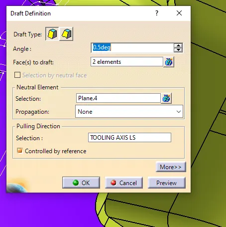
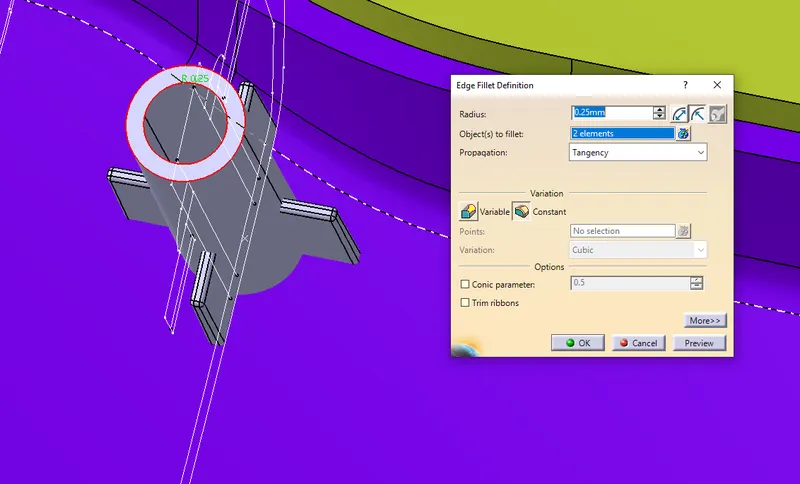
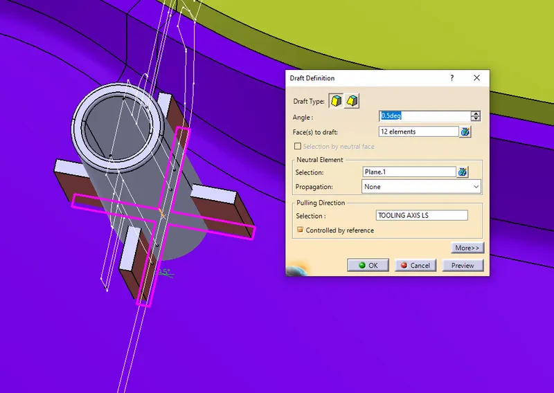
- Then using draft command give draft to the inner and outer face of the heat stakes AT 0.5 Deg and fillet the edges
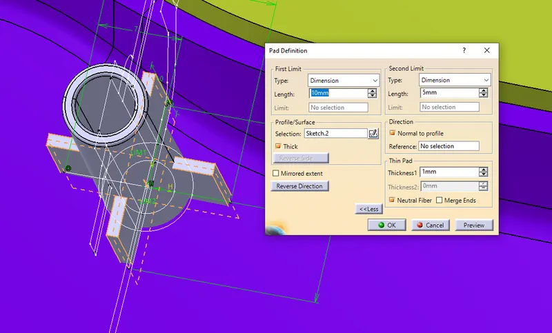
Creating ribs for the heat stake
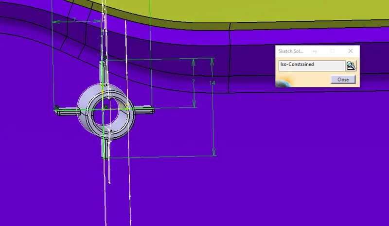
- By using heat stake mid point and that plane create a positioned sketch
- Draw the locator sketch
- Use the pad command thicken the rib
- Draft the for 0.5 degree
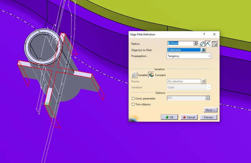
- Add fillet of 0.5mm
UNION TRIM THE HEAT STAKES AND RIBS
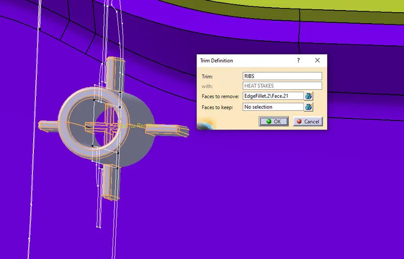
- Maintain minimum 50mm between two heat stakes
- Translate the heat stakes to wherever we need
- Assemble the heat stake to lower subtract
CREATION OF LOCATOR
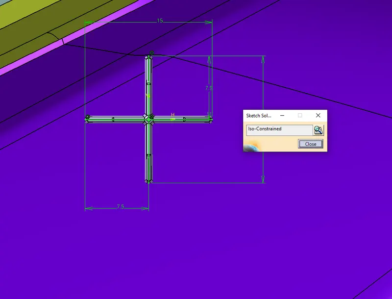
- Create a one on the surface in that going to create the locator
- And create a plane in ZX at that point
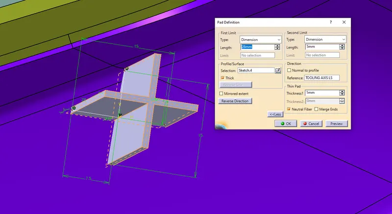
- Use positioned sketch and draw a locator sketch
- Use pad command thicken the locator and give heigth to it
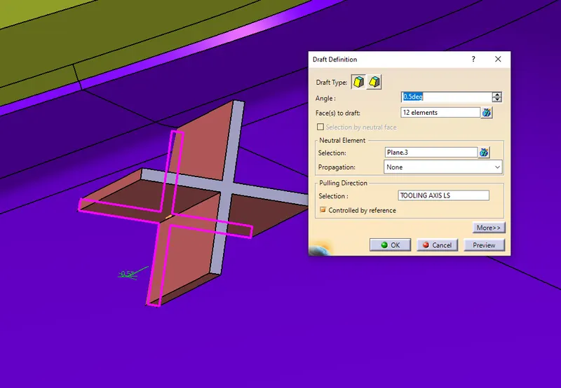
- Draft the locator for 0.5 degree
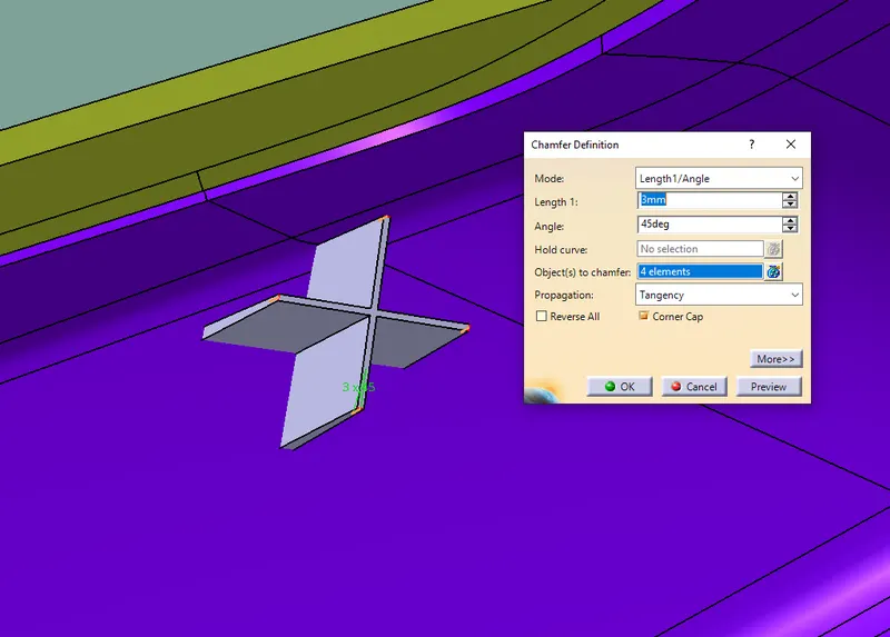
- Chamber for 3mm*45deg
- Add the Fillet of 0.5mm to all faces
- Translate the locator to required place by using translate command
- And Assemble the locator with lower substrate
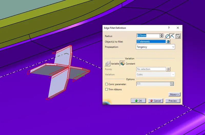
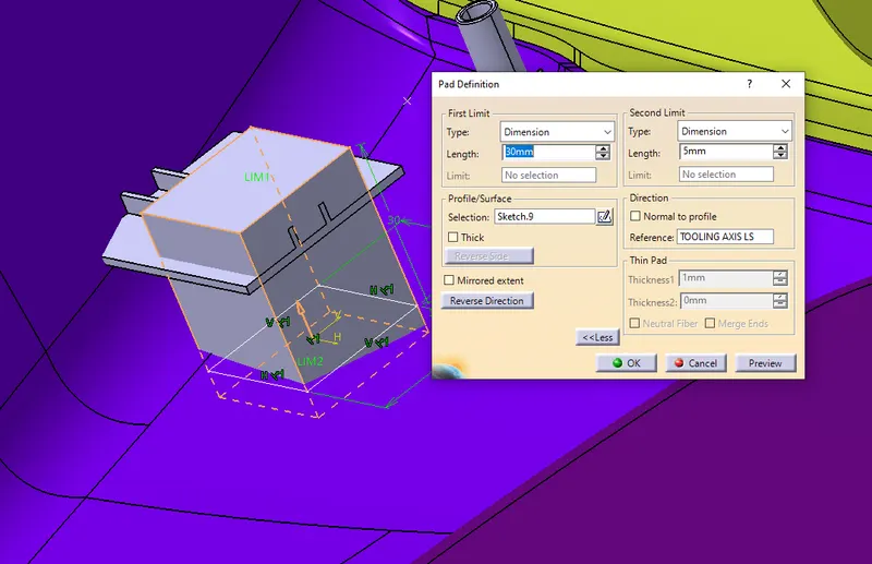
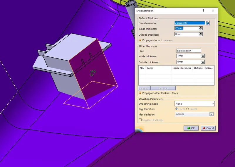
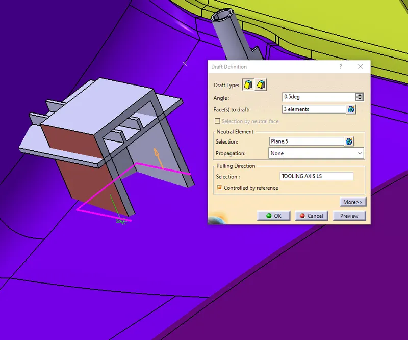
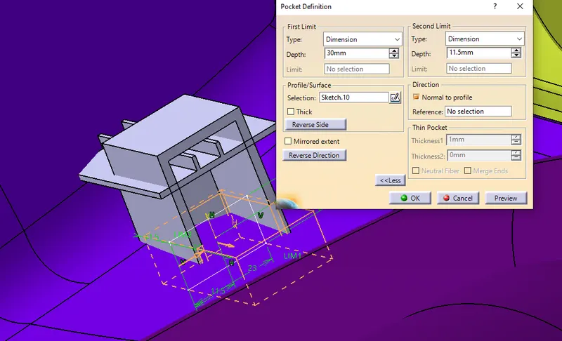
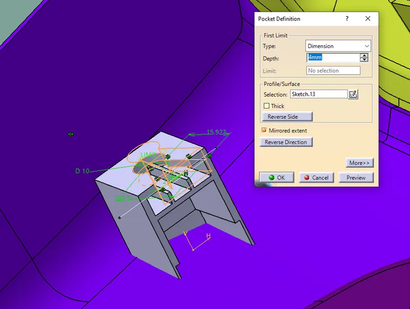
CREATION OF DOG HOUSE
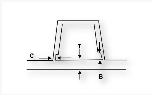
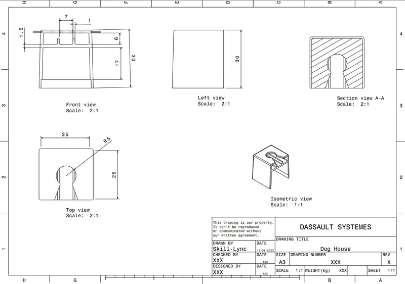
- Create a point on the surface and create a plane on the point in reference of YZ PLANE
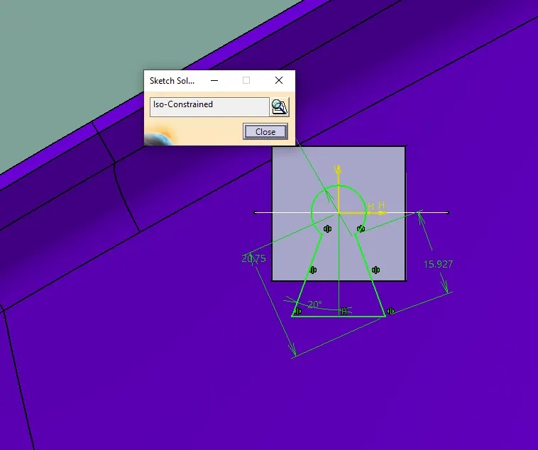
- Using positioned sketch draw the front outer view of the dog house
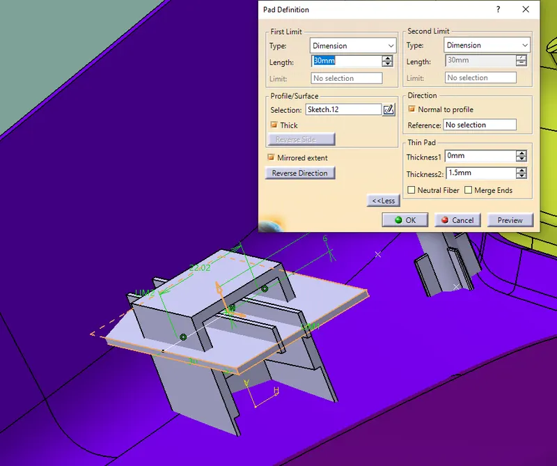
- Then using pad command thicken the dog house
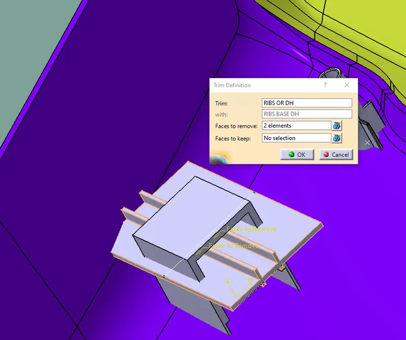
- And the front face and bottom are remove by shell command
- And make the inner ribs
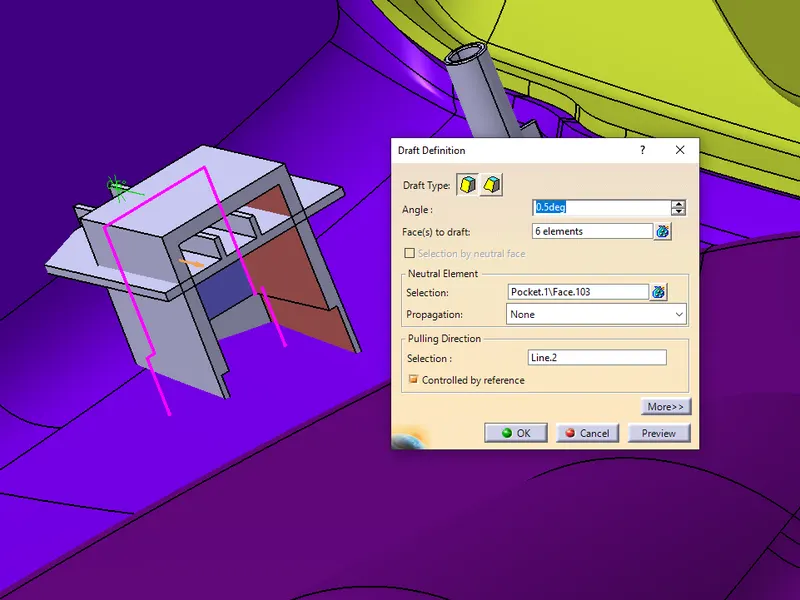
- Give draft and fillet to the dog house based on design rules
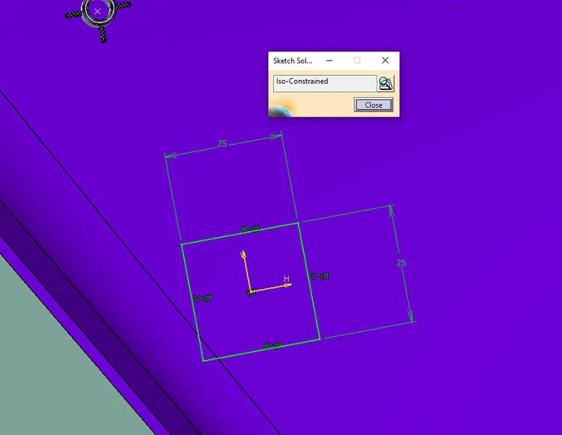
FLANGES and DRAFT ANALYSIS