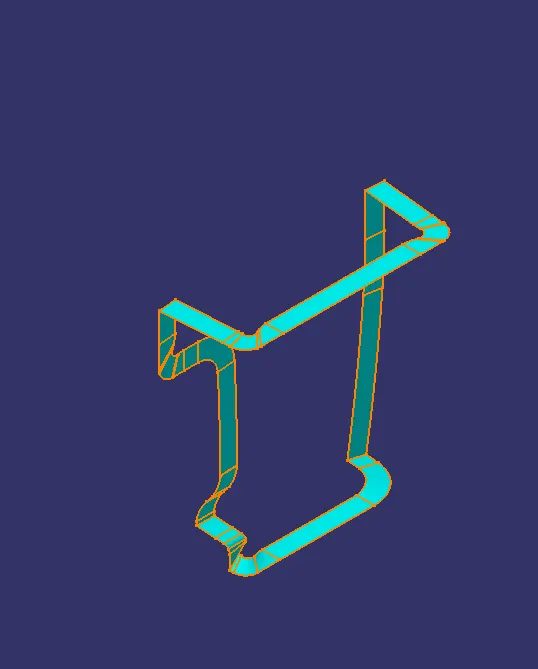
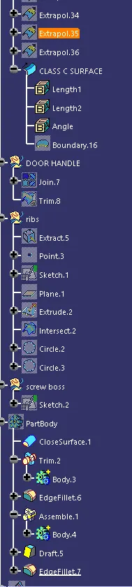
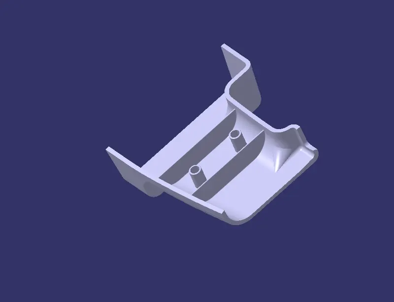
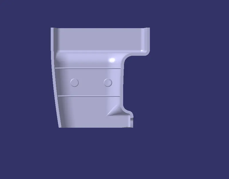
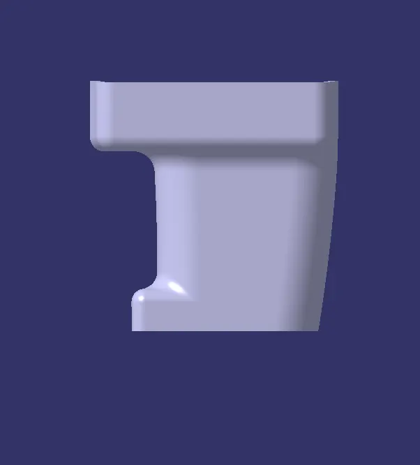
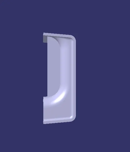
Attachment Feature Creation (Ribs & Screw Boss)
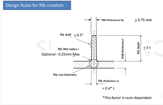
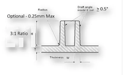
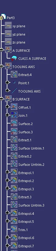
TOOING AXIS:
The tooloing Direction is basically the direction that the mold opens apart.The mold is made in two separa halves basically .you have a cavity side and core side. The core pulls apart from the cavity and thats the dye line or tooling direction.
- Check for gaps between suface for click on join and then preeview
- Extract the boundary and dissemble the boundary
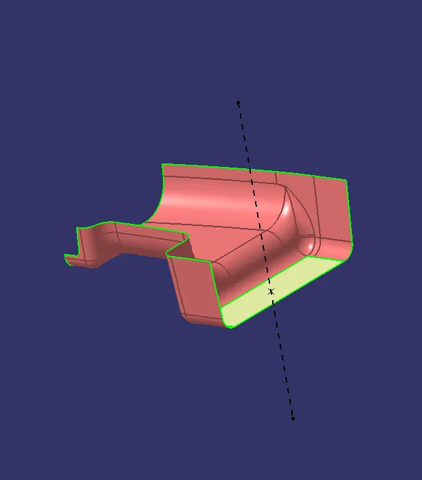
- Find the correct tooling axis where the material dont interfere with the tooling axis and all the elements can be created
- Create an axis system using at the centre of the door handle
- Intersect the YZ plane with respect to the class A surface
- Hide the class A surface and Create line on the suspected drafts
- The tooling axis is created for the component
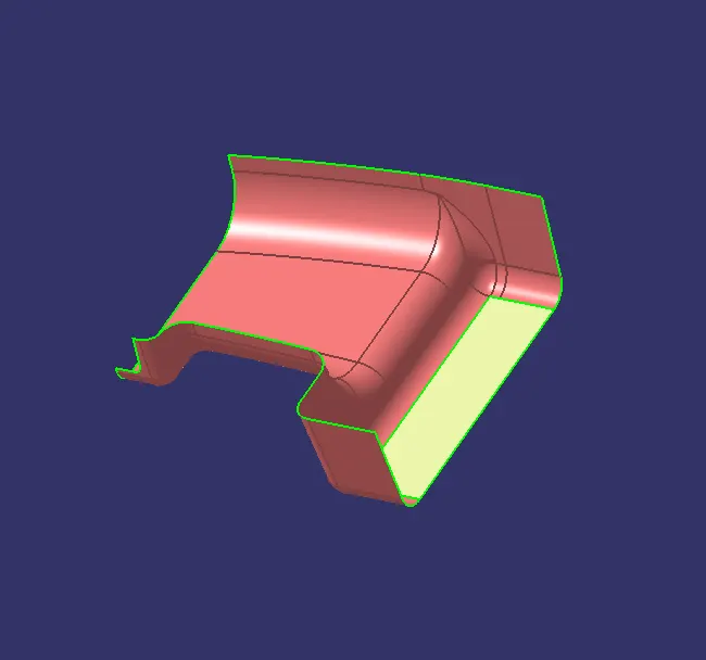
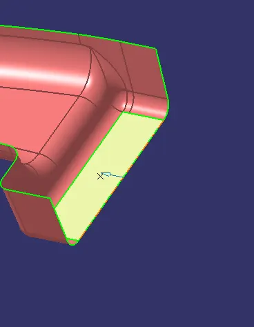
DRAFT ANALYSIS
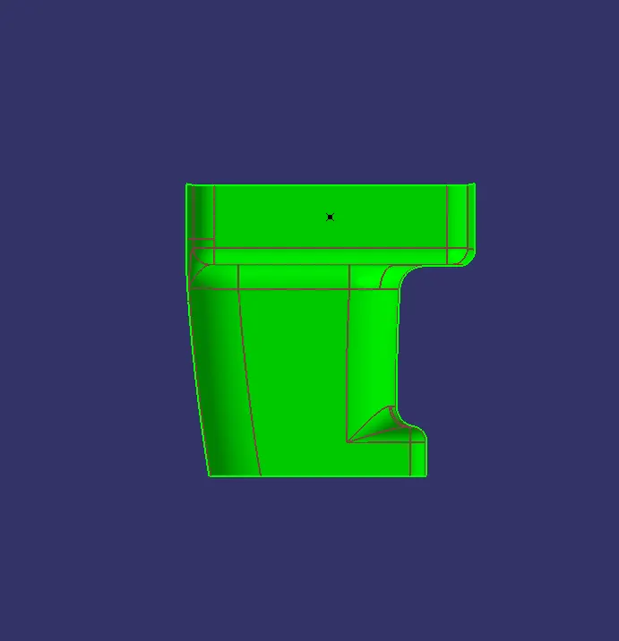
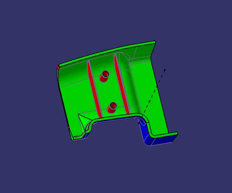
To perform draft analysis in catia Draft analysis feature is used .for that first tooling dirction decided .Then make sure materials view mode is used .After opening the window align the compass with draft analysis is need to perform in the bottom black color scale green indicated draft angle is and red denotes it is less than zero .By this way we can identify the areas with angles less than minium draft angle
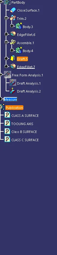
CLASS A SURFACE
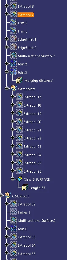
CLASS B SURFACE
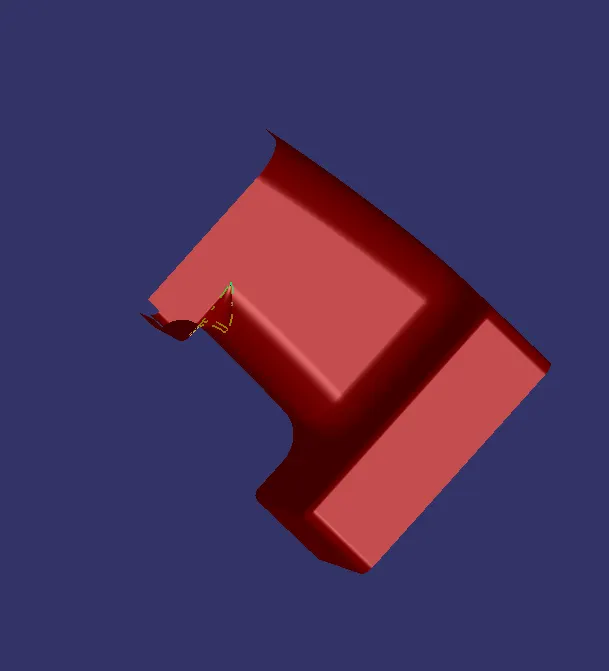
CLASS C SURFACE