Creating 3D Isometric view of various structural elements in AutoCAD
1) AIM:- To create a 3D isometric view of the given building with plan and elevation.
INTRODUCTION:-
- An isometric drawing is a 3D representation of an object, room, building or design on a 2D surface.
- One of the defining characteristics of an isometric drawing, compared to other types of 3D representation, is that the final image is not distorted.
- This is due to the fact that the foreshortening of the axes is equal.
- In an isometric drawing, the object appears as if it is being viewed from above from one corner, with the axes being set out from this corner point.
- Isometric drawings begin with one vertical line along which two points are defined.
- Any lines set out from these points should be constructed at an angle of 30 degrees.
COMMANDS USED:- Line, Rectangle, UCS, Dimlinear, Region, Extrude, Subtract, Box, Units, Dimstyle, 3Dface, 3Dorbit, Hide, Explode, Move, Copy, Dist, Solidedit, Union, Boundary, 3Dmirror, 3Drotate, Erase, Plan
PROCEDURE:-
- First we have to open the autocad and the set the maximum limit and minimum limit on the screen.
- Here first have to draw the rectangle using the rectangle command, as shown in the figure.
- Next we have to draw the two windows of sizes of 3' and 3'-2".
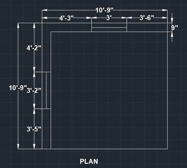
- Now we draw the elevation of A and the elevation of B, as shown in the below figures.
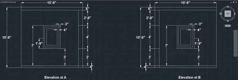
- We draw the given elevations using the line command and we put the dimensions using the dimlinear command.
- First we draw the window of the size 3' x 4'
- We draw the this window using the line command and extruded using the extrude command.
- Next we draw the window of the size 3'-2" x 4'
- We draw the this window using the line command and extruded using the extrude command.
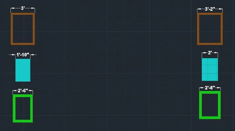
- Next we draw the walls using the extrude command.
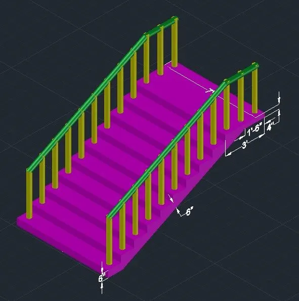
- Next we use the layers for providing the colours to them.
- Next we attach the created windows to the walls shown in the below figure.
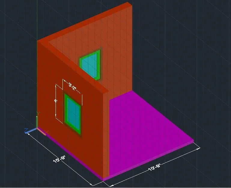
- Next we use the 3dorbit command to see the different views of the given figure.
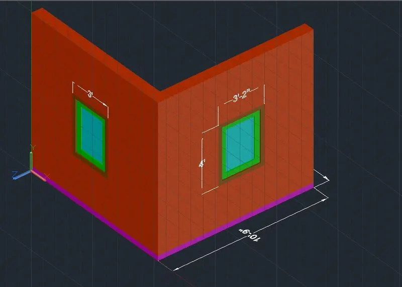
RESULT:- Hence, the given 3d isometric view of the building with plan and elevation is drawn successfully in the autocad.
2.
AIM:- To Create the 3D View of the Building Facade as given in the plan and elevation and need to create the window using the given dimensions.
INTRODUCTION:-
- An isometric drawing is a 3D representation of an object, room, building or design on a 2D surface.
- One of the defining characteristics of an isometric drawing, compared to other types of 3D representation, is that the final image is not distorted.
- This is due to the fact that the foreshortening of the axes is equal.
- In an isometric drawing, the object appears as if it is being viewed from above from one corner, with the axes being set out from this corner point.
- Isometric drawings begin with one vertical line along which two points are defined.
COMMANDS USED:- Line, Rectangle, UCS, Dimlinear, Region, Extrude, Subtract, Box, Units,, Dimstyle, 3Dface, 3Dorbit, Hide, Explode, Move, Copy, Dist, Solidedit, Union, Boundary, 3Dmirror, 3Drotate, Erase, Plan
PROCEDURE:-
- First we have to open the autocad and the set the maximum limit and minimum limit on the screen.
- Here first have to draw the rectangle using the rectangle command, as shown in the figure.
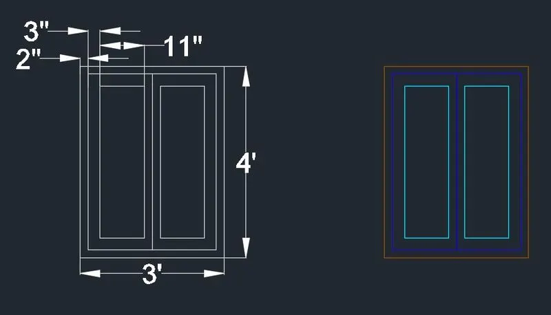
- Next we have to draw the window of size of 3' x 9".
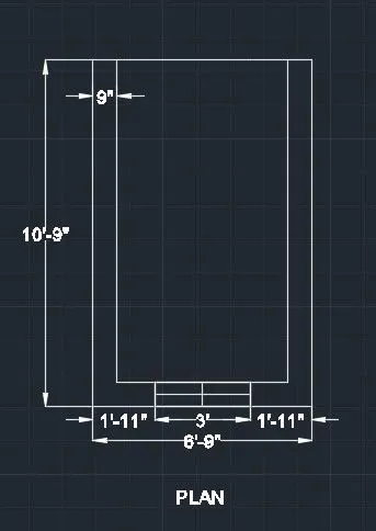
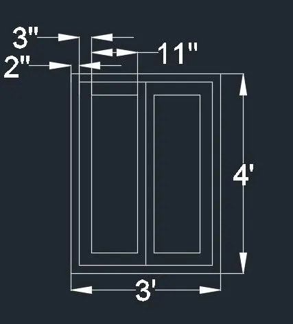
- Next we use the region command and select the objects, then press enter.
- Then after total objects will become the one region.
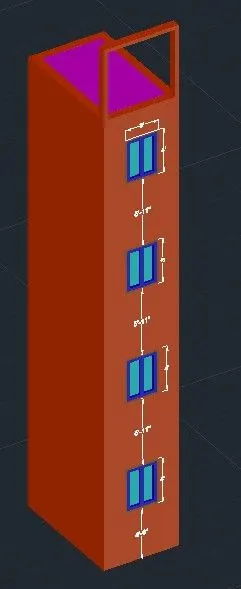
- Next we need to extrude the plan using the extrude command, with the height of 47'-3".
- Next we need to substract the four window portion vertically in a building facade with the distance 5'-11" with the window size of 3' x 4'.
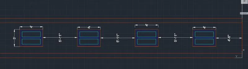
- Next we use the union command and press enter.
- Then after select the total drawing and press enter.
- Next the window portion will be clearly visible in the building facade as shown in the below figure.
- Next we select the custom visual style as shaded with edges, as shown in the below figure.
- Next provide the layers for the building facade
- Next we close the top surface of the building facade using the extrude command as shown in the below figure.
- Next we draw the window of the size 3' x 4' as shown in the below figure.
- We draw the this window using the line command and extruded using the extrude command.
- Next we use 3dorbit command to view the front elevation as shown in the below figure.

- Now put the building facade in the 3d isometric view using the 3dorbit command as shown in the below figure.
RESULT:- The given 3d isometric view of the building facade is drawn successfully in the autocad in detailed manner.
3.
AIM:- To create the ismoteric 3d view of a stair with railing as shown in the plan and elevation.
INTRODUCTION:-
- An isometric drawing is a 3D representation of an object, room, building, stairs or design on a 2D surface.
- One of the defining characteristics of an isometric drawing, compared to other types of 3D representation, is that the final image is not distorted.
- This is due to the fact that the foreshortening of the axes is equal.
- In an isometric drawing, the object appears as if it is being viewed from above from one corner, with the axes being set out from this corner point.
- Isometric drawings begin with one vertical line along which two points are defined.
COMMANDS USED:- Line, Rectangle, UCS, Dimlinear, Region, Extrude, Subtract, Box, Units,, Dimstyle, 3Dface, 3Dorbit, Hide, Explode, Move, Copy, Dist, Solidedit, Union, Boundary, 3Dmirror, 3Drotate, Erase, Plan
PROCEDURE:-
- First we open the autocad and set the maximum limit and minimum limit.
- Next we set the units as architectural and take the precison as 0'-0".
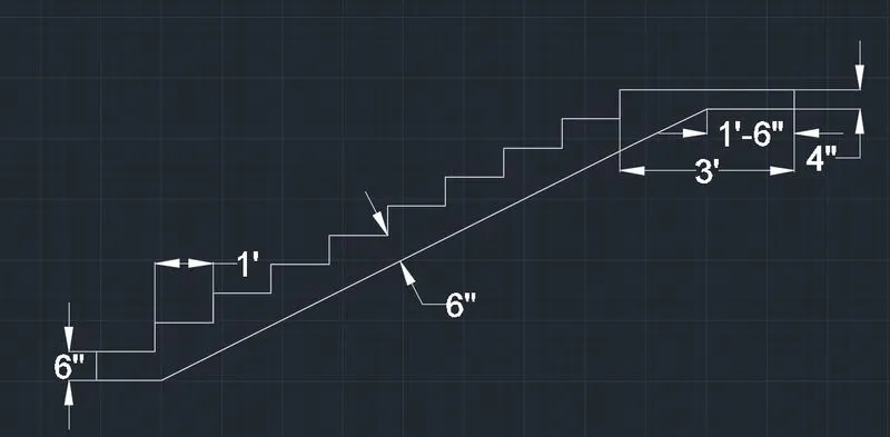
- Next we draw the stairs using the line command.
- We draw the stairs with the riser of 6" and tread of 1' as shown in the below figure.
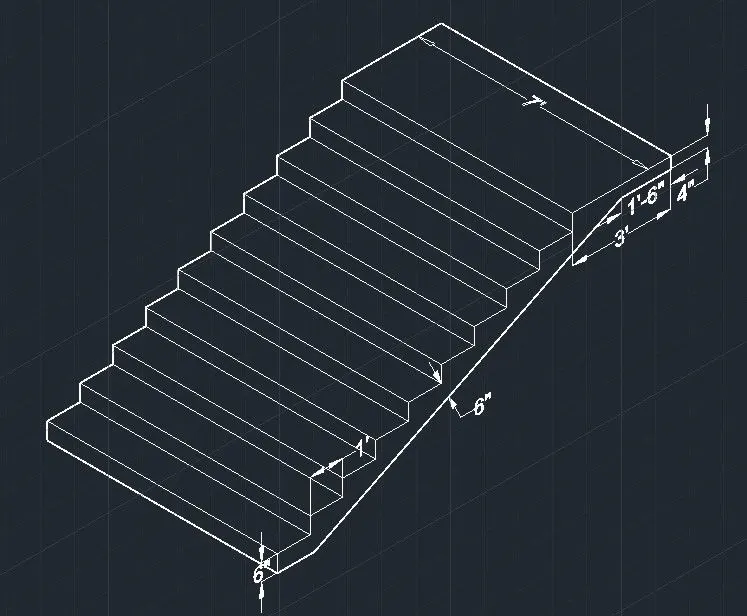
- Next we use the extrude command to extrude the figure to form the stair in 3d view.
- Next we draw the railing using the circle command and sweep command.
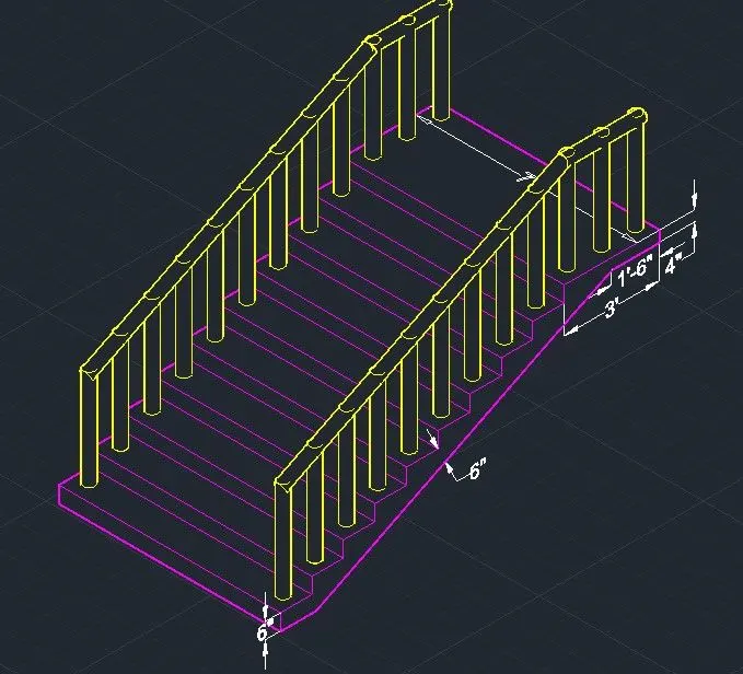
- Next we show the stairs in the side view using the 3drotate command as shown in the below figure.
- Now put the stair in the 3d isometric view using the 3dorbit command as shown in the below figure.
RESULT:- The given 3d isometric view of the stair is drawn successfully in the autocad in detailed manner.
4.
AIM:- To create the 3D view of a Wall with spread footing And need to create a rendered view of the model with materials.
INTRODUCTION:-
- An isometric drawing is a 3D representation of an object, room, building, stairs or design on a 2D surface.
- One of the defining characteristics of an isometric drawing, compared to other types of 3D representation, is that the final image is not distorted.
- This is due to the fact that the foreshortening of the axes is equal.
- In an isometric drawing, the object appears as if it is being viewed from above from one corner, with the axes being set out from this corner point.
COMMANDS USED:- Line, Rectangle, UCS, Dimlinear, Region, Extrude, Subtract, Box, Units,, Dimstyle, 3Dface, 3Dorbit, Hide, Explode, Mirror, Move, Copy, Dist, Solidedit, Union, Boundary, 3Dmirror, 3Drotate, Erase, Plan
PROCEDURE:-
- First we open the autocad and set the maximum limit and minimum limit.
- Next we set the units as decimal and take the precision as 0.
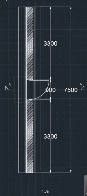
- Next we have to draw plan of wall with spread footing with given dimensions as shown in the below figure.
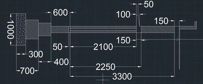
- Next we draw the 3d isometric view of the wall with spread footing using the extrude command as shown in the below figure.
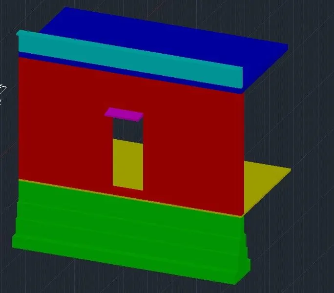
- Next provide the layers for the wall with spread footing with different colours for different parts, as shown in the above figure.
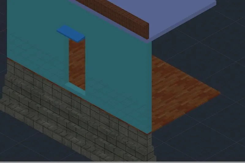
- Next we provide the different materials for the wall with spread footing, as shown in the below figure.
- We select the camera and put it in the required postion and then press enter.
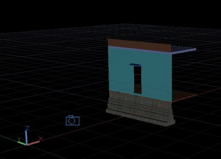
- Next click on the camera then the small tab will appears at the top of the left corner
- Finally we select the render option and then slowly it changes to the rendering view as shown in the below figure.
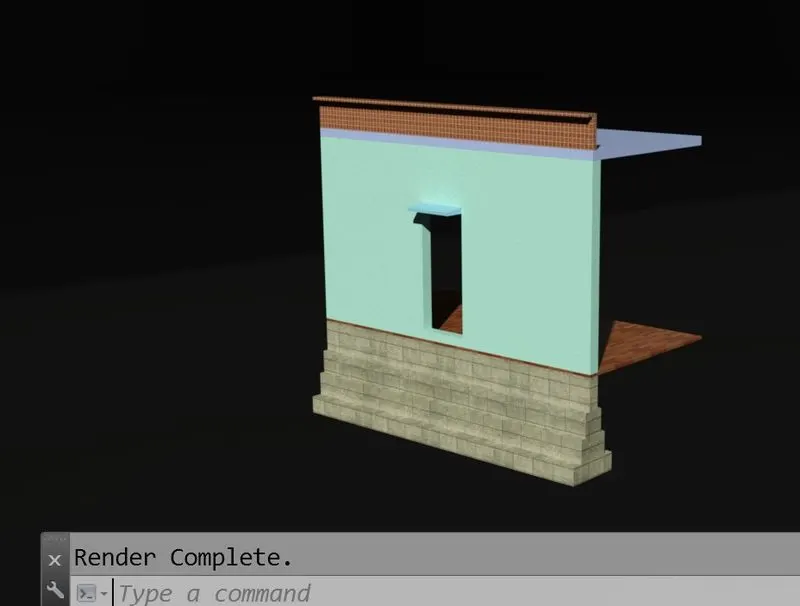
RESULT:- The 3D view of a Wall with spread footing And created a rendered view of the model with materials successfully in the autocad in detail.