1)
Aim:
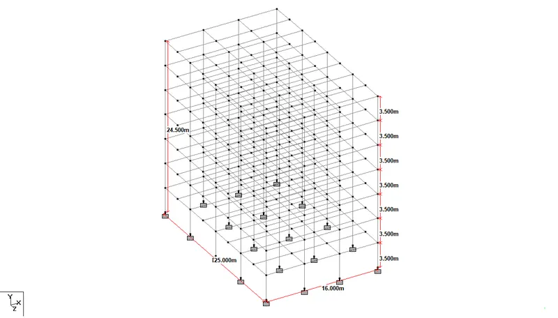
To design a multi-story Residential Building located in Bangalore using STAAD Pro Connect Edition.
Procedure:
Unit weight of the materials
Reinforced Cement Concrete = 25k
Plain Cement Concrete = 24k
Cement Concrete Screed = 20k
Cement Masonry Units = 22k
Structural Steel = 78.5k
Soil = 18k
Dead Load
Floor slab
Slab weight = 3.75k
Partitions = 1.5k
Floor Finish = 2.5k
Miscellaneous = 1k
Total Floor Load = 8.75 k
Roof slab
Slab weight = 3.75k
Insulaions and Water Proofing = 0.5k
MEP Services = 0.5k
Miscellaneous = 0.5k
Total Roof Load = 5.25k
Live Load
Floor slab
Common Corridor = 3k
Total Floor Load = 3k
Roof slab
Accessible Roof = 1.5k
Total Roof Load = 1.5k
Design of Slab
Span Shorter Direction (Clear) ly = 3.125.00 m
Span Longer Direction (Clear) lx = 5.500 m
Live Load on the Slab LL= 3.00 kN / m2
Compressive stength of concrete fck = 40 N / mm2
Yield strength of steel fy = 415 N / mm2
Unit weight of concrete Ƴ = 25.00 kN / m3
Unit weight of floor finish 100 mm Ƴ= 22.00 kN / m3
Clear concrete cover =25.00 mm
Bearing of slab B=250.00mm
Step 1
Cl 24.1
Span to effective depth ratio l/d = 32
Minimum effective depth d = 97.66 mm
Overall depth D = 127.66 mm
Provide Overall depth D = 150.00 mm
Dia of bars for short direction Φ=10mm
Dia of bars for long direction Φ = 10 mm
Effective Depth d=120.00mm
Loading on the slab
Dead Load of the slab (DL) 3.75.00kN / m2
Super Dead Load = 5.00 kN / m2
Live Load on the slab=3.00 kN / m2
Total Load on the slab (TL) =12.00kN / m2
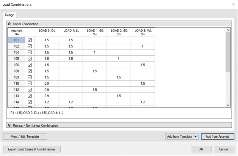
Design Load = (Total Load x Load Factor i.e. 1.5) ie 18.00 kN / m2
Effective Span lx = 5.17 m
ly=5.17 m
Ratio ly/lx= 1.000 Two Way
T26/27
1.0 ax 1.10 ay
For negative moments (at top) 0.047 0.047 0.053 0.047
For positive moments (at bottom) 0.035 0.035 0.045 0.035
Step 2
BM per unit width of slab Mx = ax w lx2 My = ay w lx2
For negative moments (at top) 22.60 22.60KN-m/m
For positive moments (at bottom) 16.83 16.83nKN-m/m
Shear force , V 0.5wlx 46.52kN/m
Step 3
To check the effective depth of slab
Mu,lim = 0.138fckbd2
d=63.99 mm
Step 4
Depth of slab for shear force
T20 τc,max =4N/mm2
τc=0.3
Cl 40.2.1 k=1.2D=200mm
τc=0.36 N/mm2
τv=Vu / bd
=0.28N/mm2
0.28 0.36 4
SAFE
Step 5
Determination of areas of steel
Mu = 0.87fyAstd(1-Astfy/fckbd)
For Negative moments Mu Top = 22.60
Ast = 463.99 mm2/m
For Positive moments Mu Bot = 16.83
Ast = 345.52 mm2/m
Step 5.1
Determination of distribution steel
Astmin =0.12bd
202.8mm2
Step 5.2
Selection of reinforcing bars
Area of bars (Top steel) =113.04mm2
Spacing =244
=240mm
Provide 12mm bars at a spacing 240mm
Area of bars (Bottom steel=113.04mm2
Spacing =327
=300mm
Provide 12mm bars at a spacing 300mm
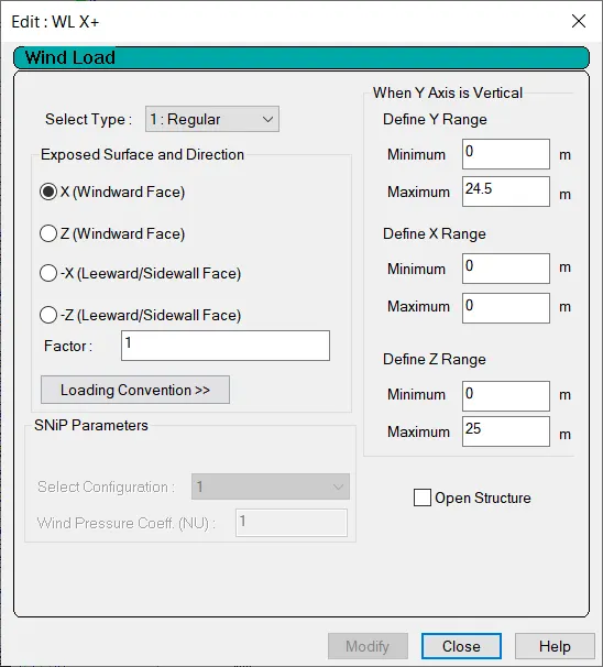
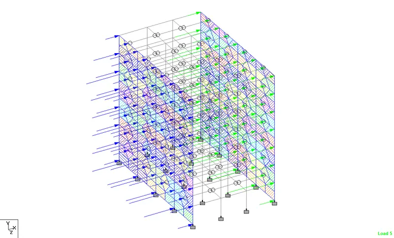
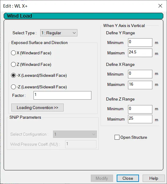
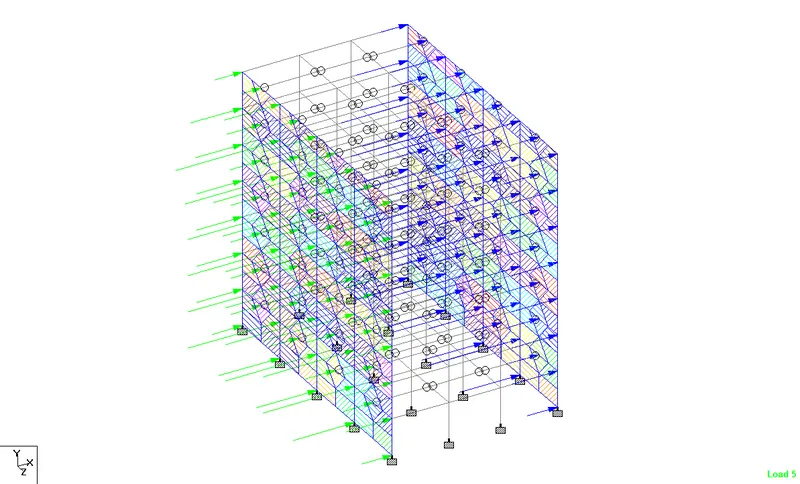
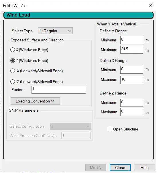
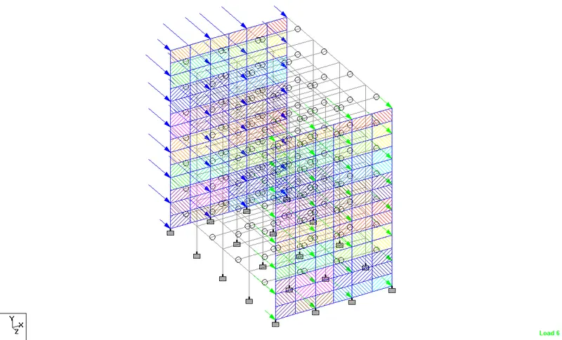
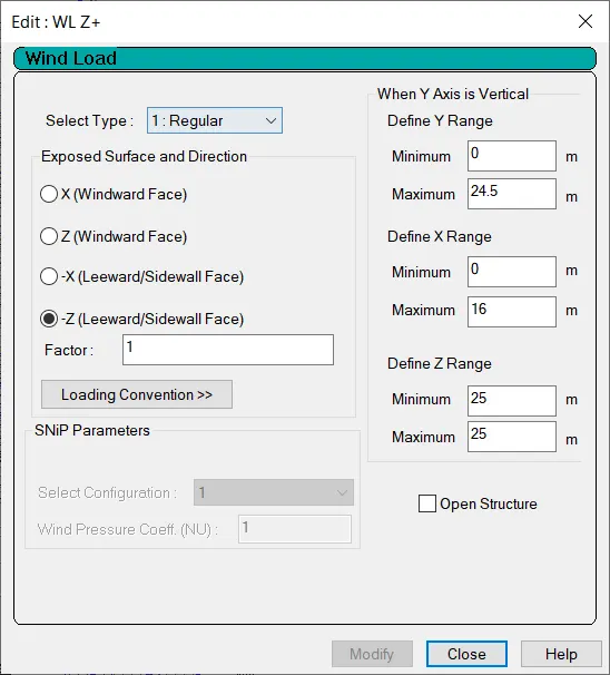
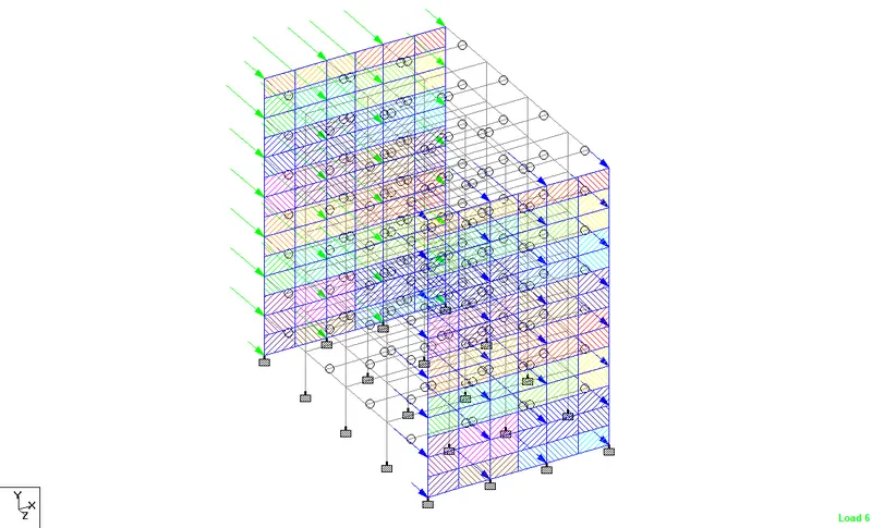
Calculation of wind load
Design Wind Speed Vz =Vb k1 k2 k3 k4 m/s
Basic Wind Speed (Banglore) Vb =33 m/s
Probability factor k1 = 1
Terrain factor , Category for k2 =Category 4 B
Topography factor k3= 1
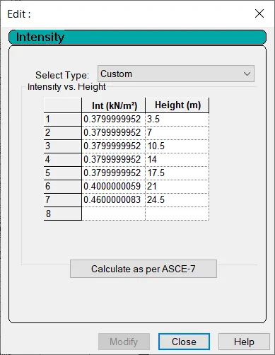
Design Wind Pressure Pz=0.6 Vz2
Height k2 Vz Pz Pz in kN
3.5 0.76 25 377.40 0.96
7.0 0.76 25 377.40 0.96
10.5 0.76 25 377.40 0.96
14.0 0.76 25 377.40 0.96
17.5 0.76 25 377.40 0.38
21.0 0.78 26 397.93 0.43
24.5 0.84 28 461.04 0.46
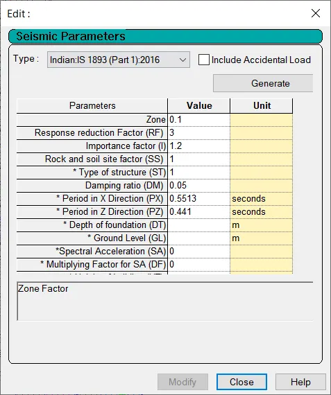
Calculation of seismic load:
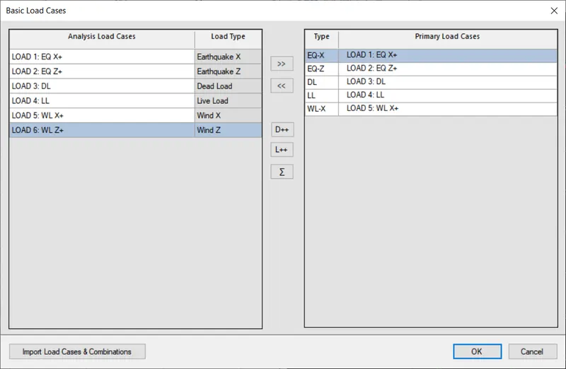
Design Base Shear VB = Ah W kN
Design Horizontal Acceleration Coefficient Ah = {(Z/2) x (Sa/g)}/(R/I)
Zone factor Z = 0.1 (Banglore)
Soil Condition factor , Sa / g
T=0.09h/[Math Processing Error]d
Height of building h=24.5m
Base dimension of building Along X = 16
Along Z = 25
T along X =0.5513s
T along Z =0.4410s
Sa / g =1.814 Along X
Sa / g =2.268 Along Z
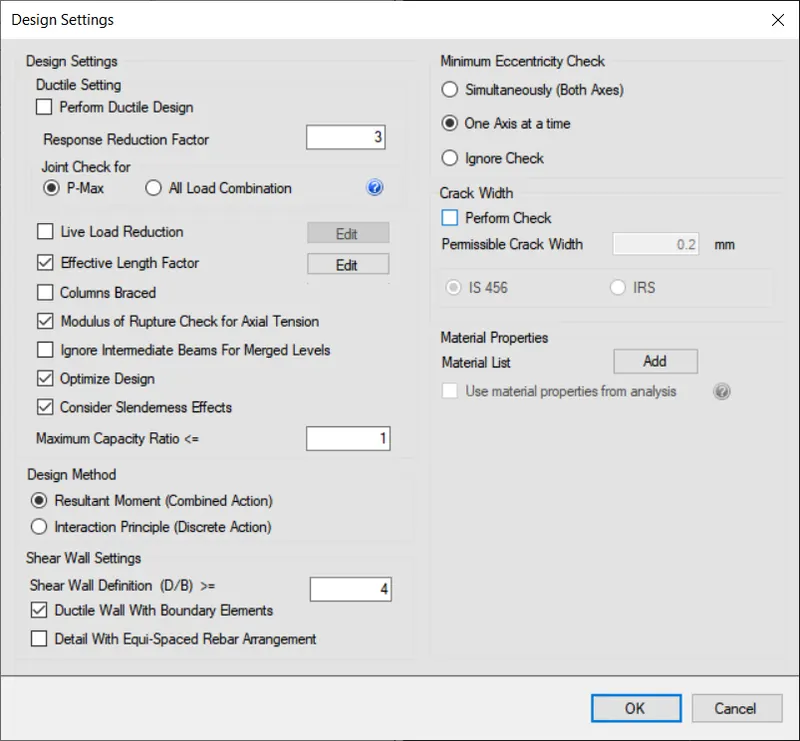
Response Reduction Factor R = 3
Importance Factor I= 1.2
Horizontal Acceleration Coefficient Ah = 0.0363 Along X
Ah =3.68%
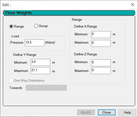
Seismic Weight
Area of Each floor A = 400m^2
Due to Dead Loads , Typical Floor DL = 12kN/m^2
W DL = 5000kN
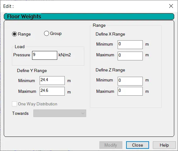
Due to Dead Loads ,Roof DL roof =9kN/m^2
=3600kN
Due to Live Loads , Typical Floor LL = 3kN/m^2
W LL = 300kN
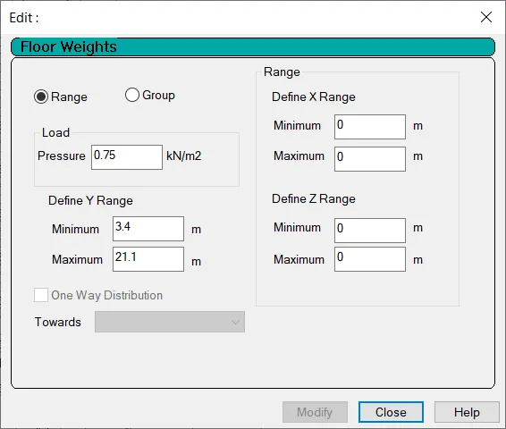
Due to Live Loads , Roof LL = 1.5kN/m^2
W LL =0
Total Seismic Weight W = 35400kN
Design Base Shear VB = 1284.35kN
Horizontal acceleration cofficient Ah= 0.0454 Along Z
=4.54%
Seismic Weight
Area of Each floor A = 400m^2
Due to Dead Loads , Typical Floor DL = 12.5 kN/m^2
W DL = 5000kN
Due to Dead Loads ,Roof DL roof =9kN/m^2
=3600kN
Due to Live Loads , Typical Floor LL = 3kN/m^2
W LL = 300kN
Due to Live Loads , Roof LL = 1.5kN/m^2
W LL =0
Total Seismic Weight W = 35400kN
Design Base Shear VB = 1605.35kN
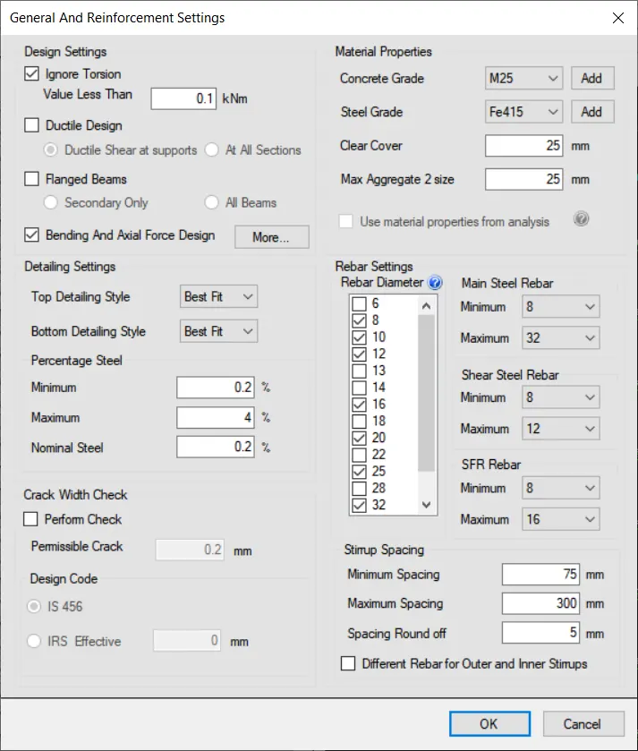
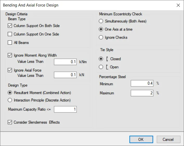
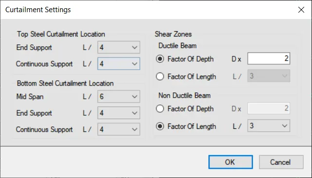
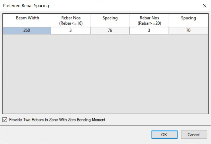
Structural design is an investigation method of the rigidity, strength and stability of the
building. The essential aim in structural analysis and design is to construct a structure capable of overcoming
all applied loads without failure during it's intended life. The process of structural design involves various
stages such as computation of loads, member design, detailing and many more. The conventional method of
structural design and analysis leads to lot of complications and tedious calculations which are time
consuming. Nowadays to complete a design and analysis in efficient manner, fast software's are used.
Computer aided design of residential building by using STAAD PRO which includes-
❖ Generating structural framing plan
❖ Getting model
❖ Analysis of structure
❖ Design of structure
1. INTRODUCTION :-
STAAD PRO has a state of art user interface, tools for visualization, well built analysis and design
software with advance finite element and capable of dynamic analysis. From generation of model, analysis
and design to visualization tools and verification of results. STAAD PRO is a common choice for steel,
concrete, aluminium and cold-formed steel design of multistorey buildings, factories, tunnels, bridges and
much more.
To perform a complete analysis, a structural engineer must find out information such as loads on structure,
geometry, support conditions and materials properties. The results of such analysis typically include support
reactions, stresses and displacements. This information is then analysed with respect to the criteria that
indicate the conditions of failure. The objective of design is the attainment of an acceptable possibility that
structures constructed will perform satisfactorily during their design life. With an appropriate degree of
safety, they should bear all loads and deformations caused due to normal construction and use and have
sufficient durability and resistance to the effects of seismic and wind. Structure along with structural
elements shall be designed by limit state design method. Account should be taken of accept theories,
experiment and experience and the requirement to design for durability. Design, including design for
durability, construction and service life should be considered as a whole. The achievement of design
objectives needs concurrence with clearly defined standards for materials, construction, workmanship and
also maintenance and use of structure in service. The design of the structure depends upon the minimum
International Journal of Modern Agriculture
ISSN: 2305-7246
Volume 10 Issue 2, 2021
Website: http://www.modern-journals.com/
2544
requirements as suggested by the Indian standard codes. The minimum requirements concerned to the
structural safety of structures are satisfied by way of laying down minimum design loads which have to be
assumed for dead loads, live loads, and others external loads, the structure would be required to bear.
1.1 Steps in structural design :
The steps involved in designing a structure are : structural planning, loads computation, analysis method,
design of member and detailing, etc.
1.2 About STAAD Pro :
It is a globally used software for design and analysis of structure by structural engineers. STAAD Pro has a
GUI-Graphical User Interface due to which we can generate the model of the structure, which is then
analyzed by STAAD engine. When analysis and design is completed, GUI can be used to view the results
graphically.
1.3 Outcomes of literature review :
Bedabrata Bhattacharjee & A.S.V. Nagender in their paper “Computer aided analysis and design of multi-
storeyed buildings” states that the design involves calculation of loads manually and analyzing entire
structure by STAAD Pro. The design methods used in STAAD Pro analysis is limit state design method with
referrence to the IS Code of Practice. STAAD. Pro has a easy to use user interface, visualization tools,
powerful analysis and design engines with advanced finite element and capable of dynamic analysis. At
initial stage they started with the analysis of simple 2-D frames and manually checked the accuracy of the
software with the results. The results proved to be very accurate. They analyzed and designed a G+7 storey
building[2- D Frame] initially for various load combinations. Mr. K. Prabin kumar, R. Sanjaynath in their
paper “A study on design of multi-storey residential building - a review” concluded that at first, the planning
of the structure is done using AutoCAD. Calculations of loads were done manually and then the structure
was analyzed using STAAD Pro. STAAD Pro is straightforward to use so as that the frame are going to be
drawn, load values and dimensions are given. The method used in STAAD Pro analysis is limit state method.
STAAD Pro is able to calculate the reinforcement required for any concrete section. Different structural
action is considered on members such as torsion, flexure, axial, etc. Shear reinforcement is sufficient to
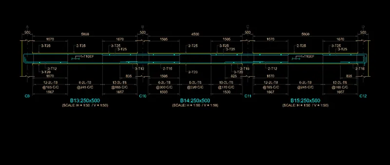
withstand each shear forces and torsional moments. Beams are designed for flexure, shear and torsion.
Columns are delineated for axial forces at the ends. The building is planned as per IS: 456-2000. Arjun Sahu,
Anurag Verma , Ankit Singh, Aryan Pal , Mohd. Shariq in their paper .“Design & analysis of multistorey
(g+3) residential building using STAAD Pro & AutoCAD” stated that Planning, analysis and design of G+3
multi-storey residential building is done using STAAD Pro and AutoCAD. It’s a G+3 storied building with
parking in the ground floor and the remaining floors are occupied with apartments. All the structural elements
were designed manually and detailed using AutoCAD. The analysis and design were done based on standard
provisions using STAAD Pro for static and dynamic loads. The dimensions of structural members are
specified and the loads such as live load, dead load, earthquake load and floor load are applied. Deflection
and shear tests are checked for columns, slabs and beams
Result & Conclusion
Thus the multi-story Residential Building located in Bangalore has been designed for the given input.